Project
Projecttitel: Syncussion SY-1M
Status: FINISHED
Startdate: 10 May 2018
Duedate: 15 May 2018
Manufacture link: http://www.psycox.co.uk
Attention, this guide is only for the psycox Version SY-1M , the main difference on this Version is the addional Midi function, Matched SMD Transistors and improved powersupply.
check my SY-1 page for the thehumancomparator version.
further links:
general discussion
https://www.muffwiggler.com/forum/viewtopic.php?t=195208&start=0
http://www.psycox.co.uk
BOM:
MOUSER BOM https://www.mouser.com/ProjectManager/ProjectDetail.aspx?AccessID=1305 e9618c
MOUSER/DIGIKEY BOM Cross-reference : VIEW IN GOOGLE DOCS
or use both to get the best price:
they seem correct now and save you nearly 50€ when ordering parts. remove from one list: the 220uF caps the CD4069UBE 10uF capacitors change the PSU DC-JACK to the same as powersupply is (2.1mm or 2.5mm) add 4x 1nF styroflex or C0G capactors for the CD4069UBE VCOs |
C1 C2 C8 C10 must be a C0G/NP0 or Styrene (polypropylene caps do not fit due to their size, maybe)
order 4xC0G : 810-FK28C0G2A102JN06
or 4x Styrene: 23PS210
BUILD DOC: (v1.2) DOWNLOAD
MIDI REFERENCE DOC: DOWNLOAD
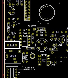
BOARD REFERENCE SHEET sy_1m_board_reference_sheets_825.zip
Original Schematics Pearl Syncussion: schematics.pdf
my addional build tipps:
- the first provided BOM was wrong, the included FLAT pushbutton (this ~7mm height switches aren´t needed), the correct 2 pushbutton switches (~12mm height ) are included for the first batch. (ordered until April 2018)
- the groundpads are not easy to solder, i prefer to use leadfree soldercore for this pads (clean this pcb sections after soldering)
- Change R63 to 1K to get the best noise gain
Power Input
the BOM use a 2,5mm middle Pin powerconnector BUT the most powersupplys use a 2.1mm middle pin, you can´t use a 2.1mm powersupply with a 2.5mm connector.
the most webshops have more 2.1mm powersupplys in stock and 2.1mm is the defacto standard.
middlepin is +
Spec: DC 7.5V output with 300mA or more
Pinheader assembly
- solder one the pin header to the pcb
- shorten the pin stripes by 1mm-2mm
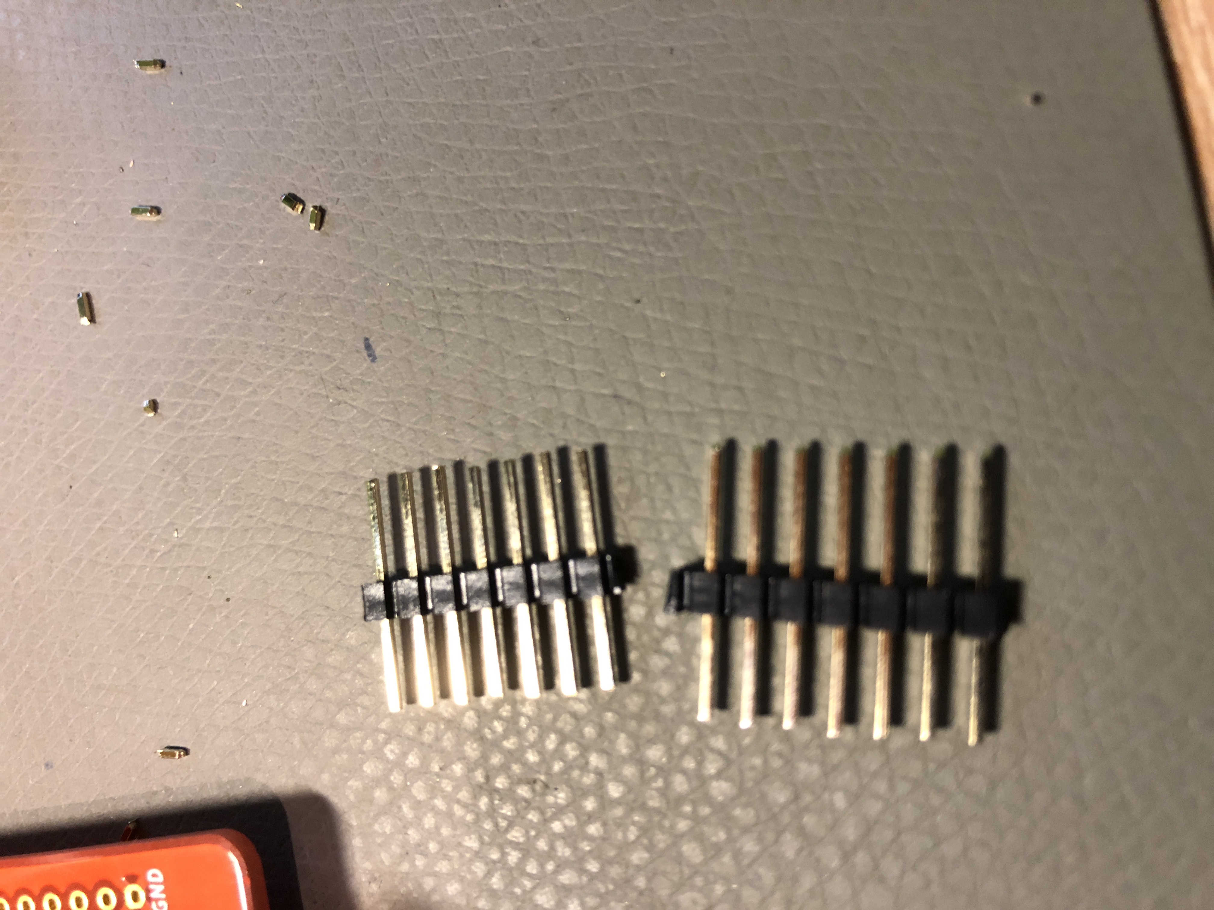
- plug the pin stripes in the hader, it has to be full in it - like this:
- now attach on the top a further pinheaderlike this: (the same is on the right side with the 3pin header, the 4pin header dont must be shorten because the header don´t have the same height.
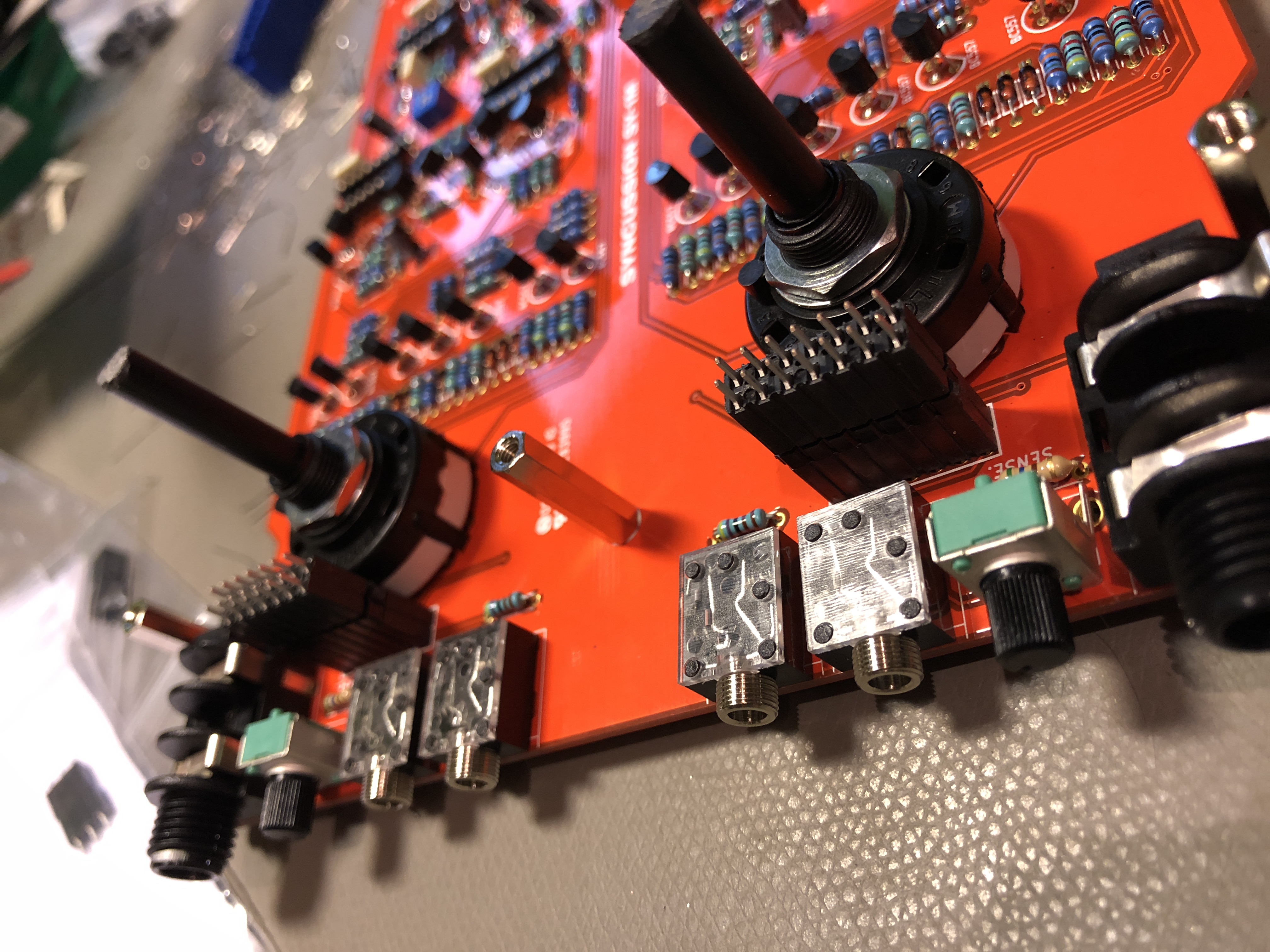
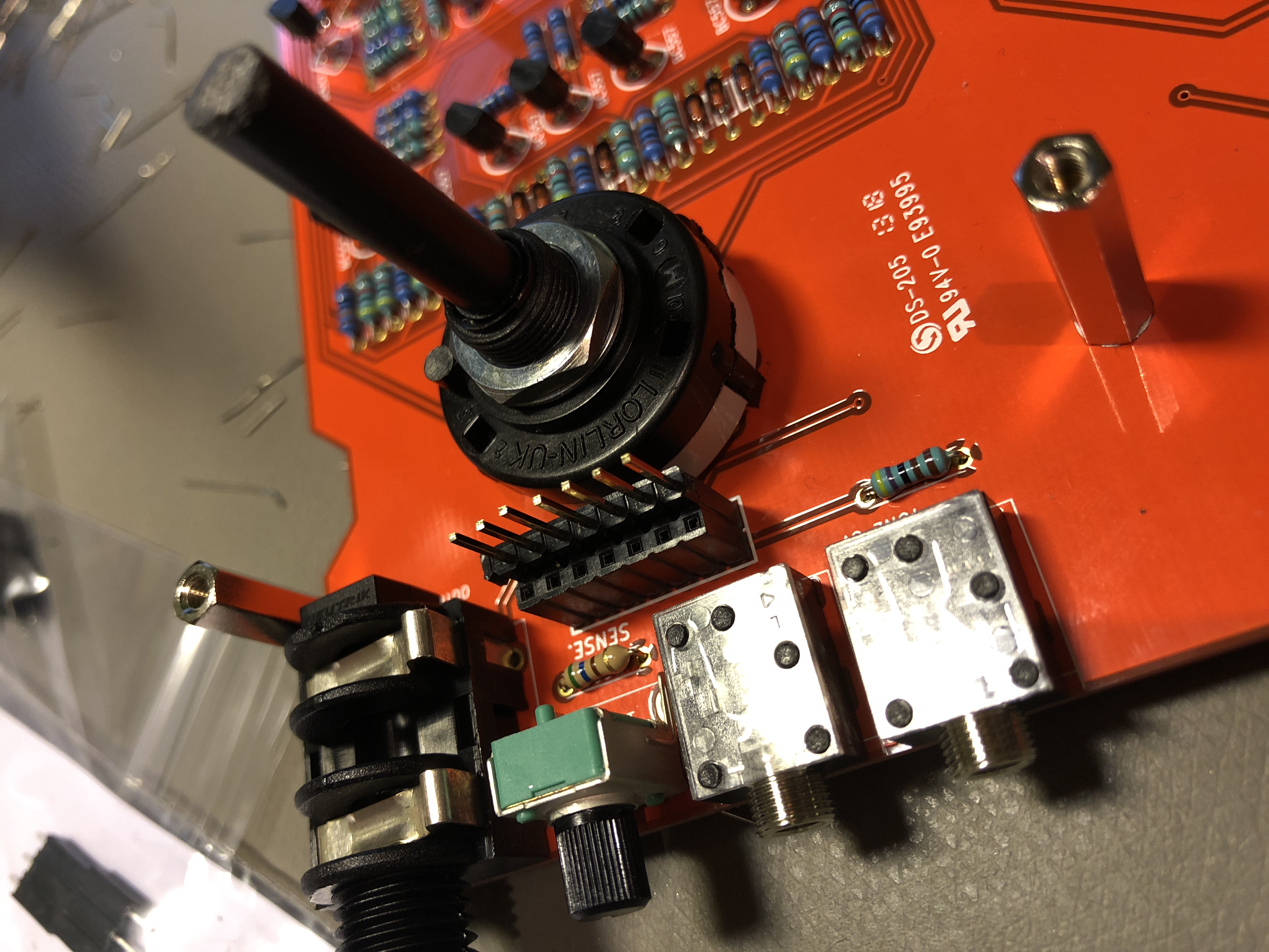
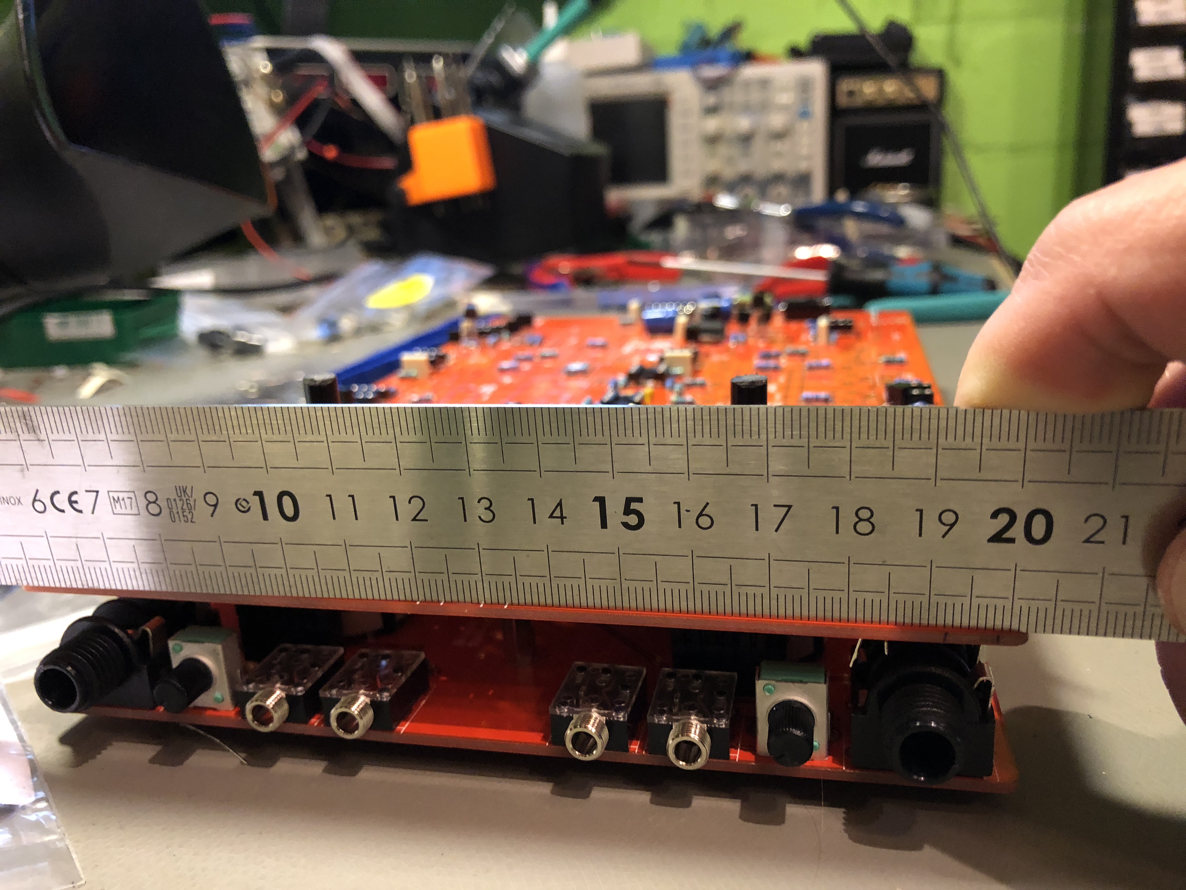
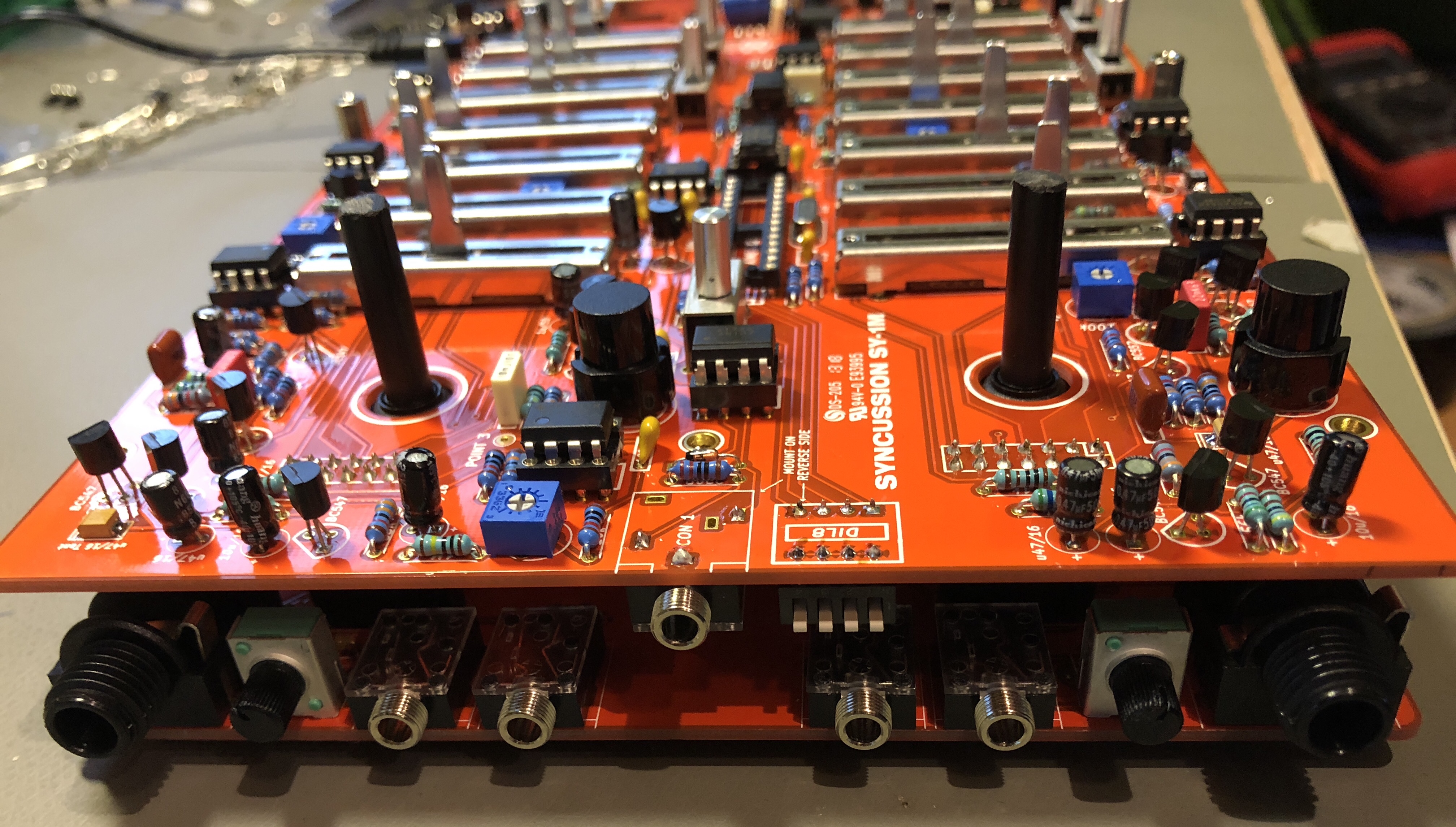
before you solder the pinheaders to the top pcb
make sure the pcb is flat and do not bend.
make sure you solder the MIDI channnel switch, midi input jack and power input to the bottom side like :
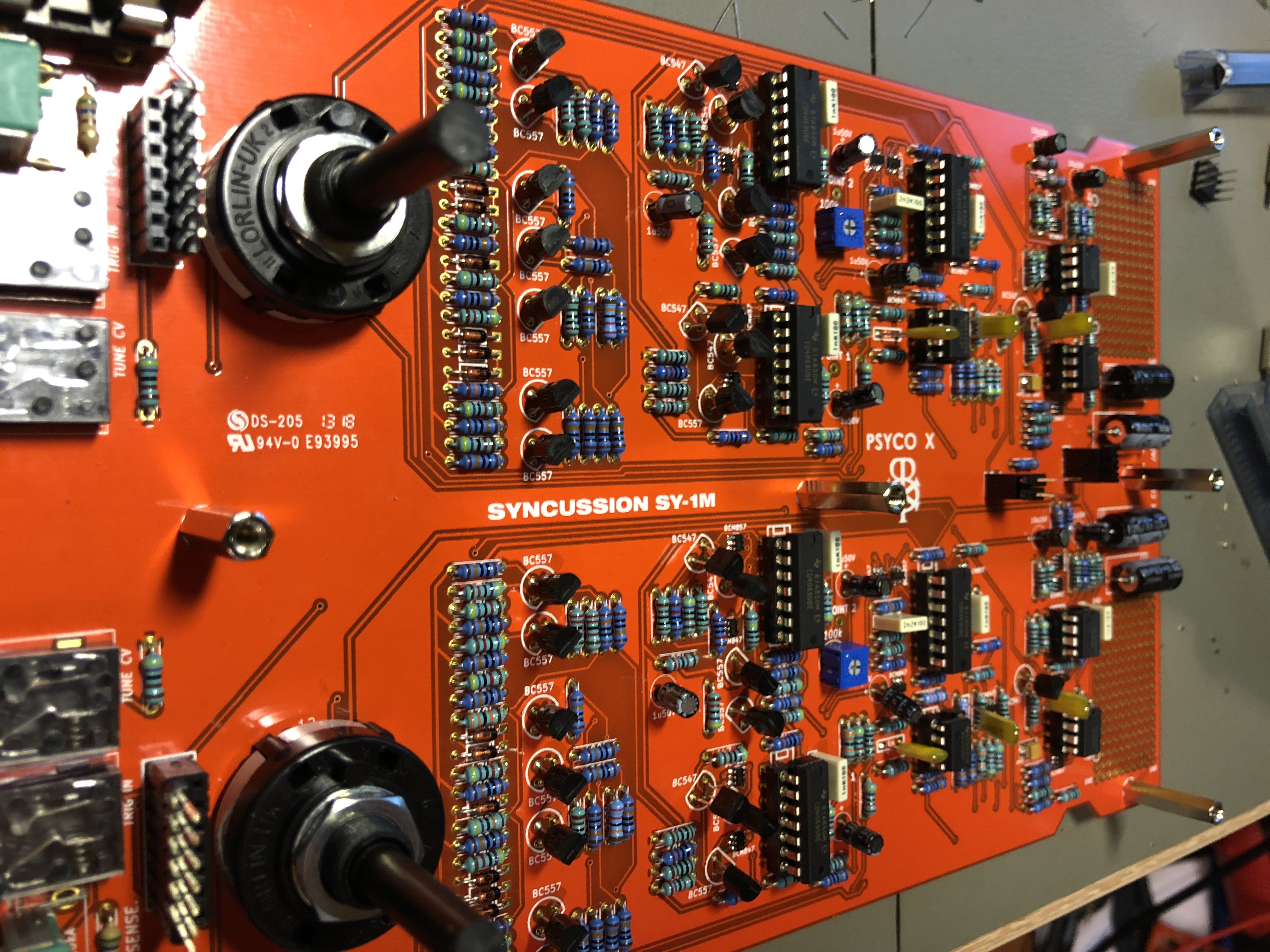
if you have everything soldered and you´re ready for the first test, make sure all IC´s and THT Trannys have the correct orientation, dont install the ATMEGA for the first test
please doublecheck the polarity of your powersupply, middle pin is +
set the powerswitch to off,
connect the powersupply
more Pictures...
| There are no images attached to this page. |