Project
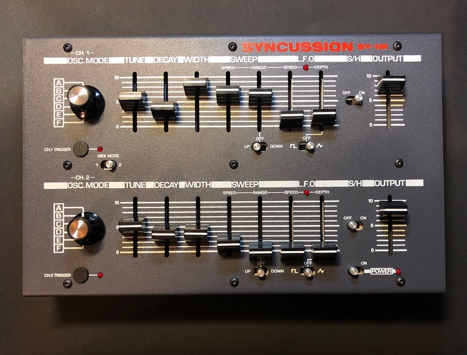
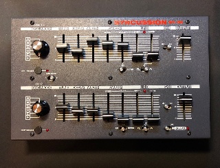
Projecttitel: Syncussion SY-1M
Status: FINISHED
Startdate: 10 May 2018
Duedate: 15 Jun 2018
last update: 05 Sep. 2018
Manufacture link: http://www.psycox.co.uk
Facebook group: https://www.facebook.com/groups/237916856594386/?ref=bookmarks
Attention, this guide is only for the psycox Version SY-1M , the main difference on this Version is the addional Midi function, Matched SMD Transistors and improved powersupply.
check my SY-1 page for the thehumancomparator version.
if you need help in SMT soldering or looking for a person who build the device, feel free to ask me Impressum - Info
Table of contents
further links:
general discussion
https://www.muffwiggler.com/forum/viewtopic.php?t=195208&start=0
http://www.psycox.co.uk
BOM:
make sure you know which PCB Version you have
for SY-1M rev.1 (sold in Arpil 2018) MOUSER BOM https://www.mouser.com/ProjectManager/ProjectDetail.aspx?AccessID=1305 e9618c
or use rev.1 MOUSER/DIGIKEY BOM Cross-reference : VIEW IN GOOGLE DOCS
for rev.2 (sold since 05.September 2018) https://www.mouser.com/ProjectManager/ProjectDetail.aspx?AccessID=b83daa5bf6
for rev.1. and rev.2:
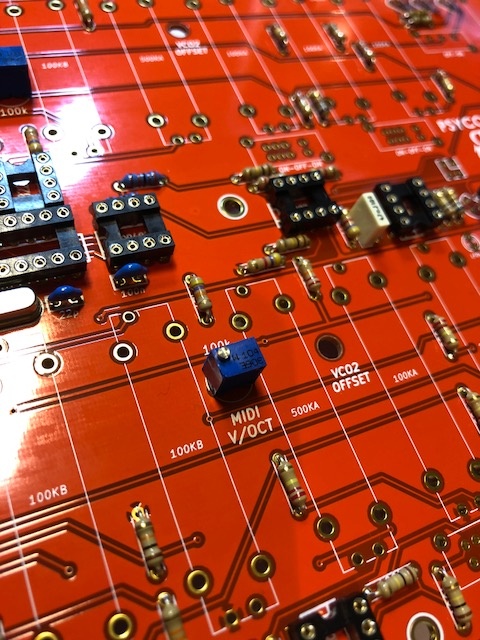
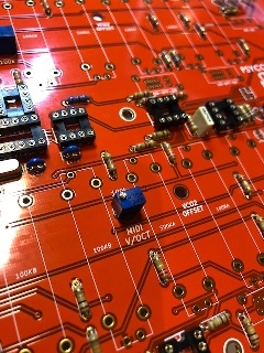
add 2x Multiturntrimmer for CV V/Oct or 4x if you want multiturn for V/OCT Midi too.
order: T67W-100K from tme.eu or from mouser:
858-67YR100KLFTB
rev.1 customers from europe:
they seem correct now and save you nearly 50€ when ordering parts. remove from one list (because the´re few parts double) the 220uF caps the CD4069UBE 10uF capacitors change the PSU DC-JACK to the same as powersupply is (2.1mm or 2.5mm) add 4x 1nF styroflex or C0G capactors for the CD4069UBE VCOs |
for both versions: (not in BOM)
C1 C2 C8 C10 must be a C0G/NP0 or Styrene (polypropylene caps do not fit due to their size, maybe)
order 4xC0G : 810-FK28C0G2A102JN06
or 4x Styrene: 23PS210
Important files:
rev.1 Build doc. DOWNLOAD
rev.2 Build doc. DOWNLOAD
Midi Reference doc. DOWNLOAD
Board Reference sheet: sy_1m_board_reference_sheets_825.zip
Original Schematics Pearl Syncussion: schematics.pdf
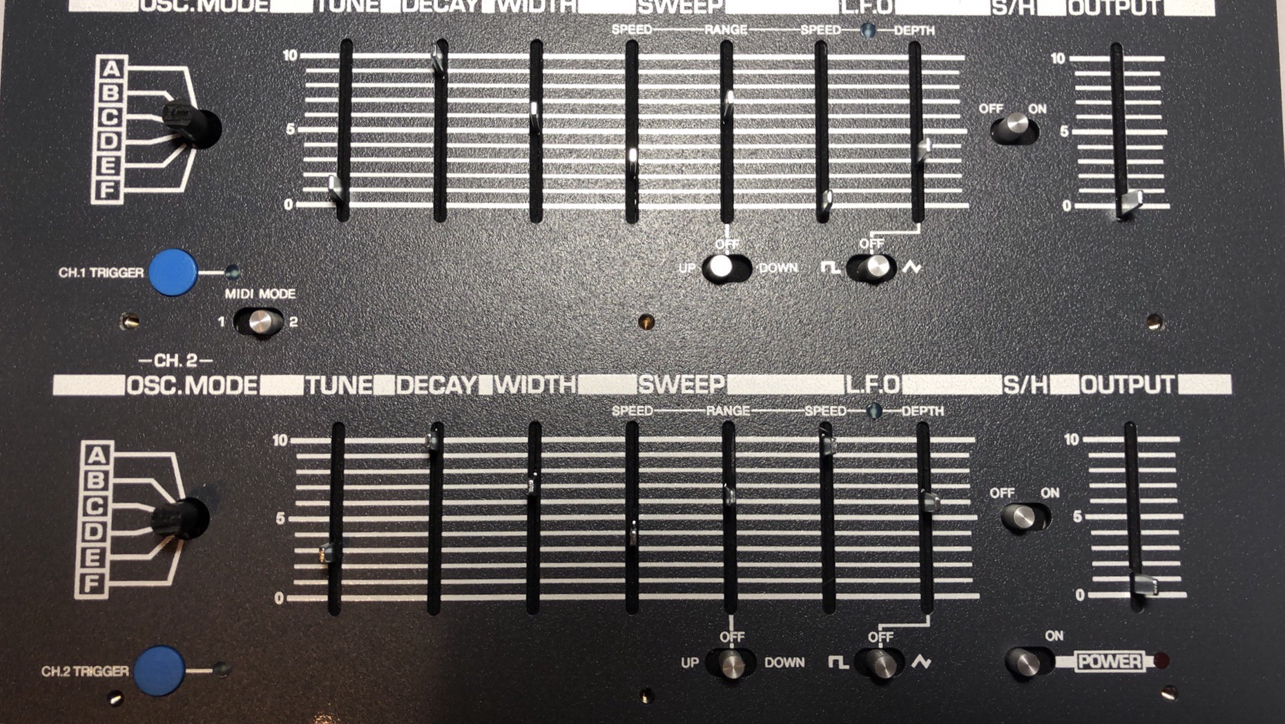
Usage VCO modes:
A VCO 1 only
B VCO 1 modulates VCO 2 frequency, the latter is routed to the VCF
C Both VCO to the filter but VCO1 at reduced level.
D EG 1 modulates VCO1, EG2 modulates VCO2. Both VCO to the filter
E VCO 1 modulates VCO 2 which has a sawtooth wave. VCO 2 to VCF
F Noise to VCF, no oscillators
HOWTO SMT ASSEMBLY:
my addional build tipps:
- the first provided BOM was wrong, the included FLAT pushbutton (this ~7mm height switches aren´t needed), the correct 2 pushbutton switches (~12mm height ) are included for the first batch. (ordered until April 2018)
- the groundpads are not easy to solder, i prefer to use leadfree soldercore for this pads (clean this pcb sections after soldering)
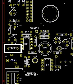
- Change R63 to 1K to get the best noise gain or use a 2SC1815 like in the original (with reversed pinout and a 10K resistor for R63)
- for calibration: R10 and R42 must be grounded or the VCO frequency goes down and down - also you can try to trigger with a sequencer while calibration the syncussion.
Power Input
the BOM use a 2,5mm middle Pin powerconnector BUT the most powersupplys use a 2.1mm middle pin, you can´t use a 2.1mm powersupply with a 2.5mm connector.
the most webshops have more 2.1mm powersupplys in stock and 2.1mm is the defacto standard.
middlepin is +
Spec: DC 9V output with 300mA or more, 12v Powersupplys works too, but the regulators only waste the voltage to heat
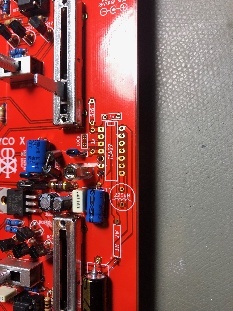
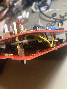
Pinheader assembly
- solder one the pin header to the pcb
- shorten the pin stripes by 1mm-2mm
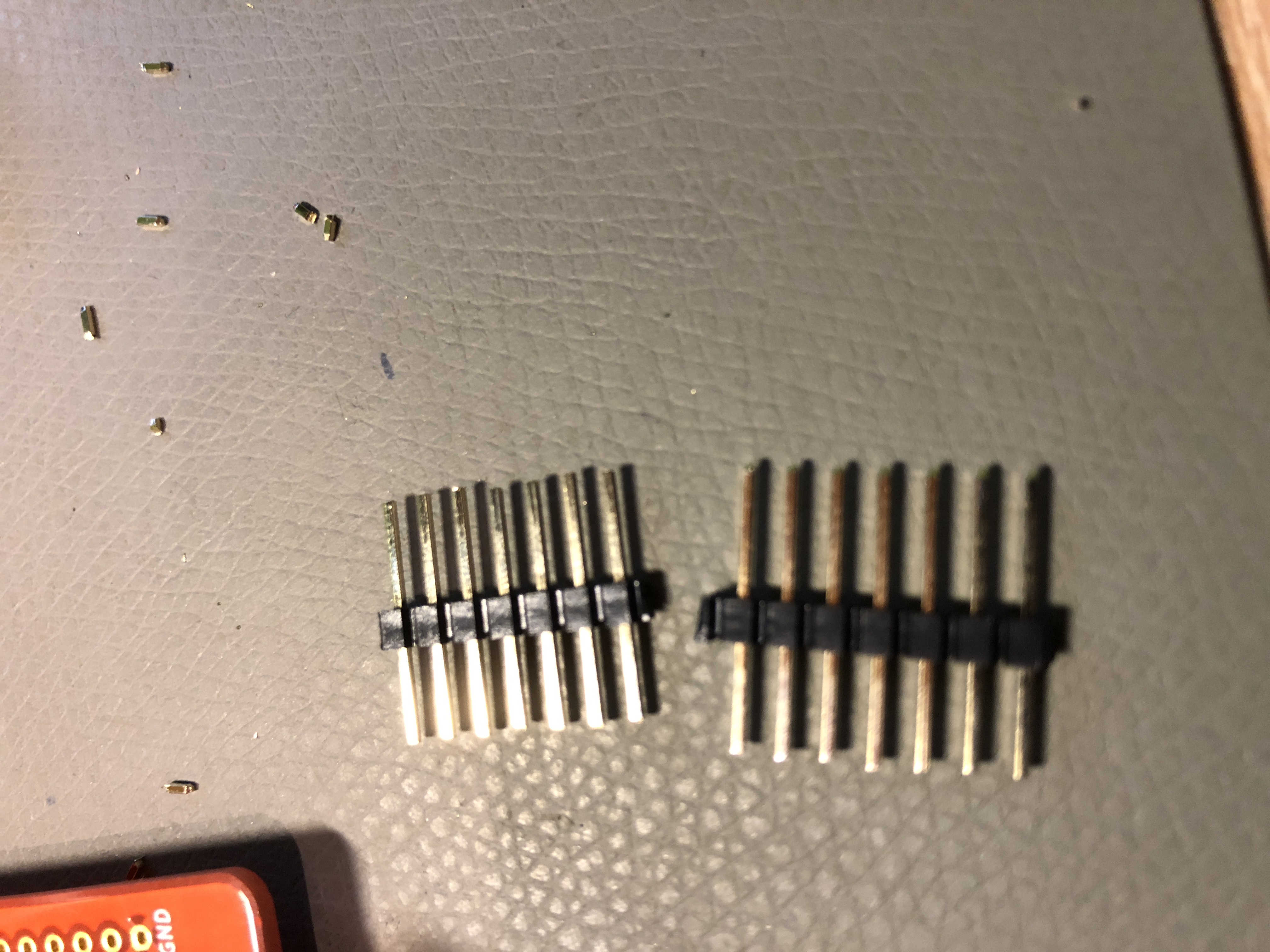
- plug the pin stripes in the hader, it has to be full in it - like this:
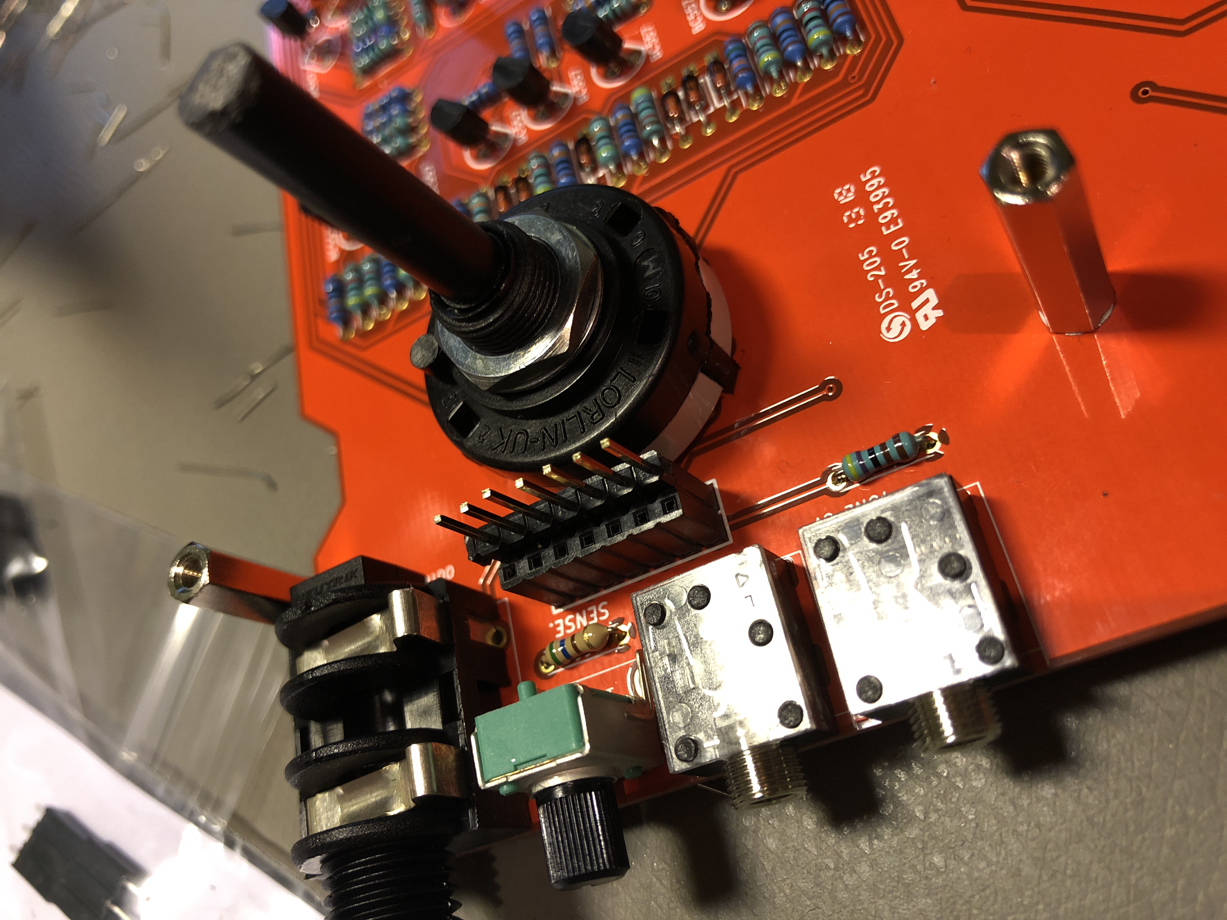
- now attach on the top a further pinheaderlike this: (the same is on the right side with the 3pin header, the 4pin header dont must be shorten because the header don´t have the same height.
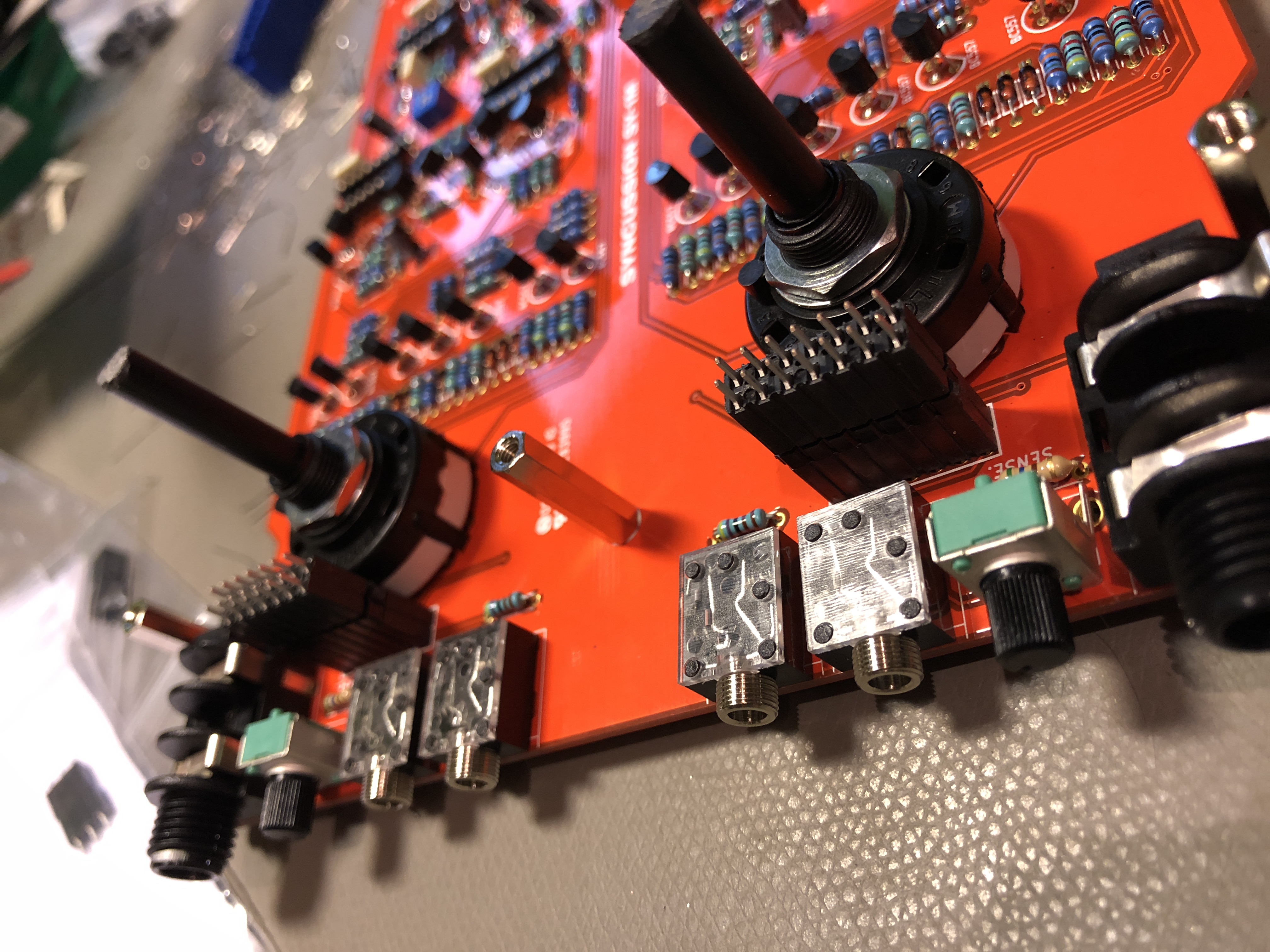
before you solder the pinheaders to the top pcb
make sure the pcb is flat and do not bend.

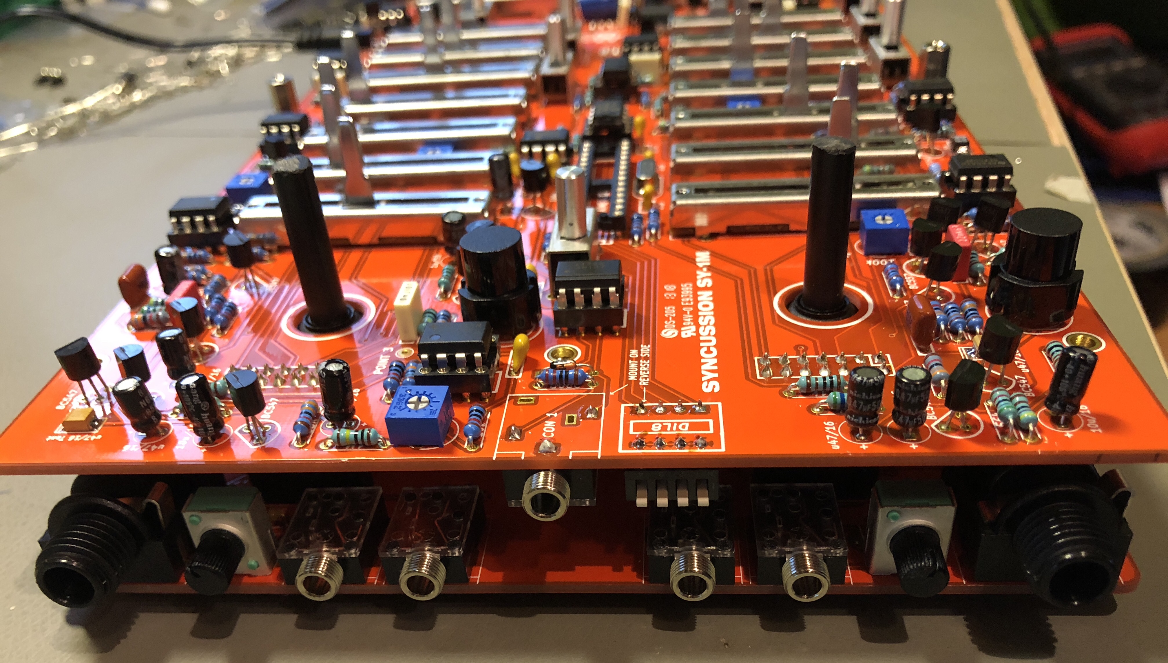
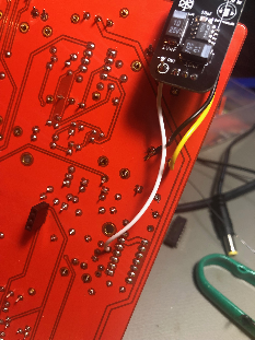
make sure you solder the MIDI channnel switch, midi input jack and power input to the bottom side like :
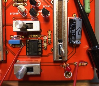
if you have everything soldered and you´re ready for the first test, make sure all IC´s and THT Trannys have the correct orientation, dont install the ATMEGA for the first test
please doublecheck the polarity of your powersupply, middle pin is +
set the powerswitch to off,
connect the powersupply
Changes/mods
- the original Syncussion use a 2SC1815 in the noise section, i tried in one build this type (with reversed pinout) and a 10K resistor for R63, the result is the same like with BC54,
no difference in sound, gain etc.
- use Multiturn trimmer for CV V/OCT and Midi v/oct
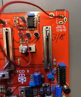
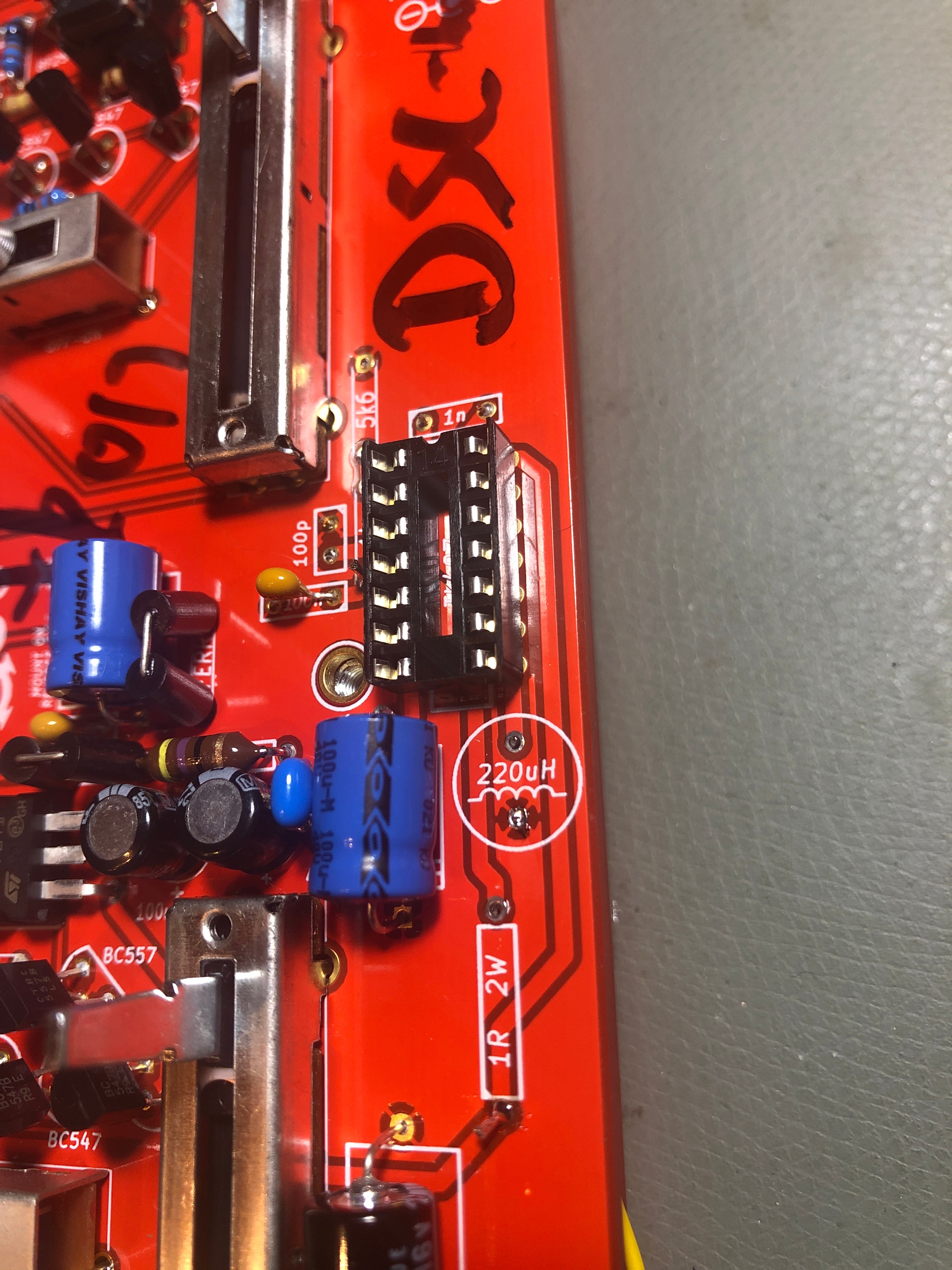
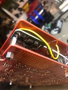
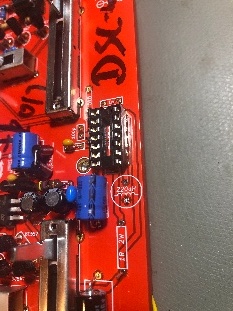
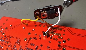
Power Modification
install on new build:
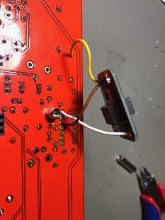

preinstall in case your coil makes hizz/hum: (click to enlarge)

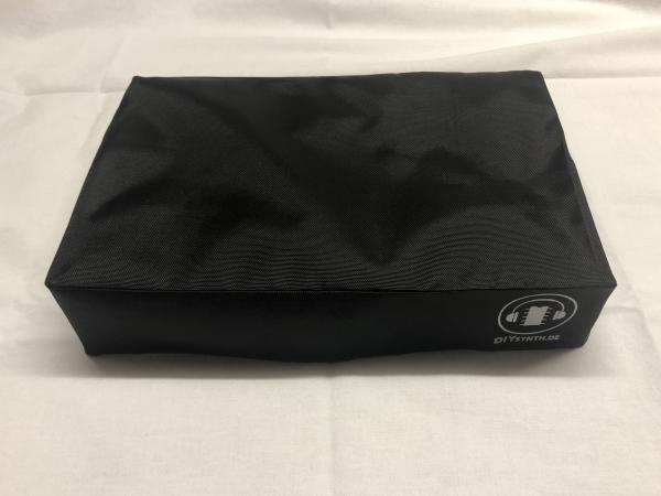
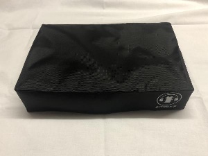
Dustover
https://www.diysynth.de/?cat=c17_Staubschutzhuellen-Staubschutzhuellen.html
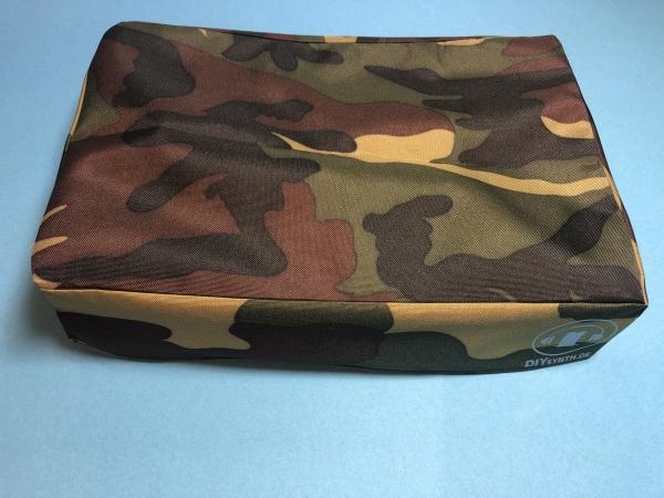
Dustcover mats:
http://synthronics.de/dust-covers_syncussion_sy-1m/
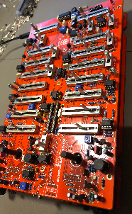
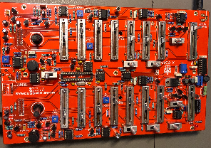
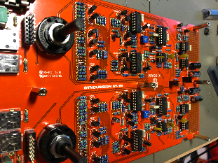
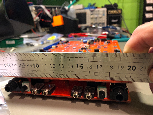
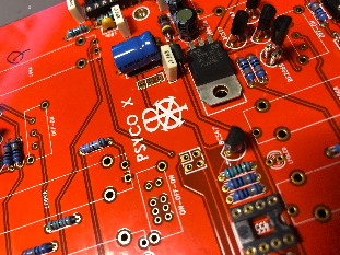
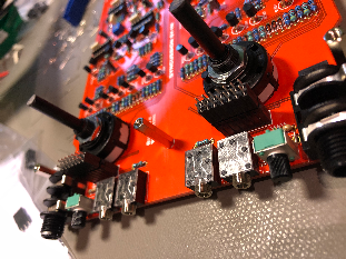
Gallery
|
|
|
|
|
|
|
|
|
|

|
|
|
|
|
|
|

|
|
|

|
|
|
|
|
|
|
|
|
|
|||