Project
Projecttitel: VS-1
Status: IN BUILD
Startdate: 06/2020
Duedate: 04/2024
Updated: 09.Feb.2024
Manufacture link: http://abstraktinstruments.com
https://abstraktinstruments.com/vs1-diy/
Facebook group: (I´m the admin). https://www.facebook.com/groups/849435342474238
send me a message if you dont get access
Modwiggler Build thread:
This Pages are only especially for the DIY Version
The Kickstarter campaign is online since: 14.Jan.2020 and was sucessfully backed with 250K USD
Table of Contents
Generel Info bit the Kickstarter goals:
Stretchgoals:
- 120K - MPE Support
- 140K - Direct Outputs
- 160K - Stereo Analog Chorus - We have a hell of an analog chorus designed - we can't add cost & commit resources to implement it unless we reach certain cost targets.
- 180K SD Card
- all Stretch Goals arrived
BOM:
VS-1_DIY_BOM(v102).xlsx from 04.Jan.2024
VS-1_DIY_BOM(v103).xlsx from 24.Jan.2024
VS-1_DIY_BOM(v104).xlsx from 09.Feb.2024 please look at t he changeling in the BOM, in case you used the BOM 1.03 previous.
Soldercore
you need 2 solder core types:
Digikey:
- water soluble solder core, this is the solder core which you use for resistors,capacistors, IC-sockets, parts which can be in touch in water.
https://www.digikey.de/de/products/detail/kester-solder/24-6337-6403/6048
part nr. 24-6337-6403
Digikey:
2. no clean solder core - which must be used for trimmers and potentiometer (everything which has to be installed after you washed the pcbs with hot water)
part nr. 24-6337-8809
Schematics: (copy from 09.Feb.2024)
Build it:
Please see the Altium 365 Viewer documentation for full details on the cloud-based tool.
Mainboard
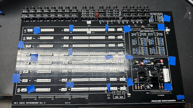
Voice Motherboard
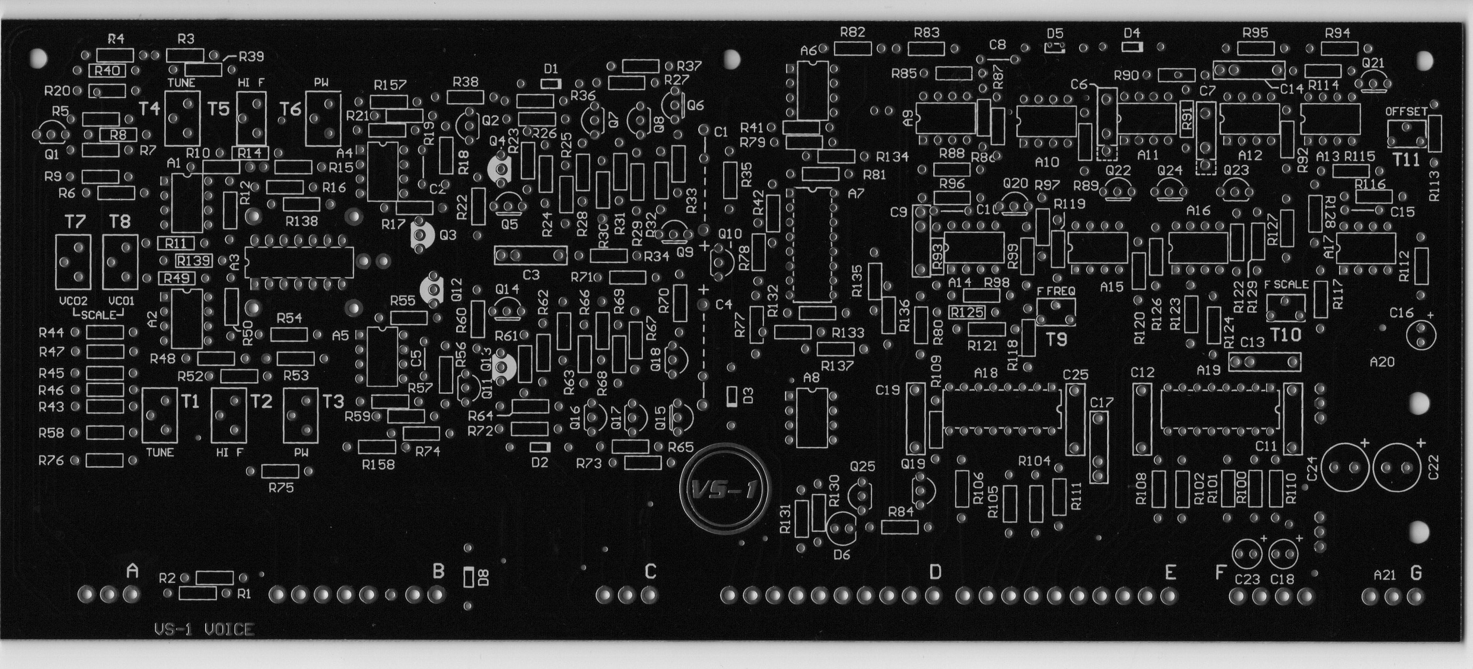
Voice Card
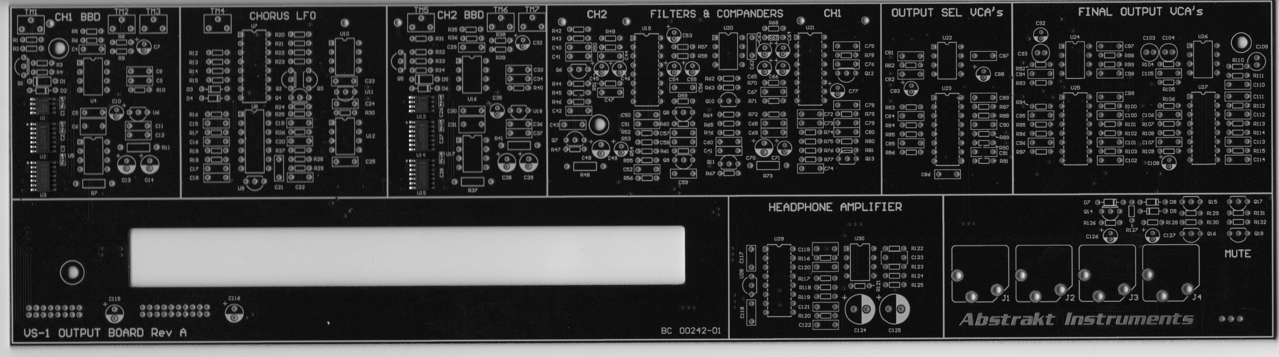
Output Board
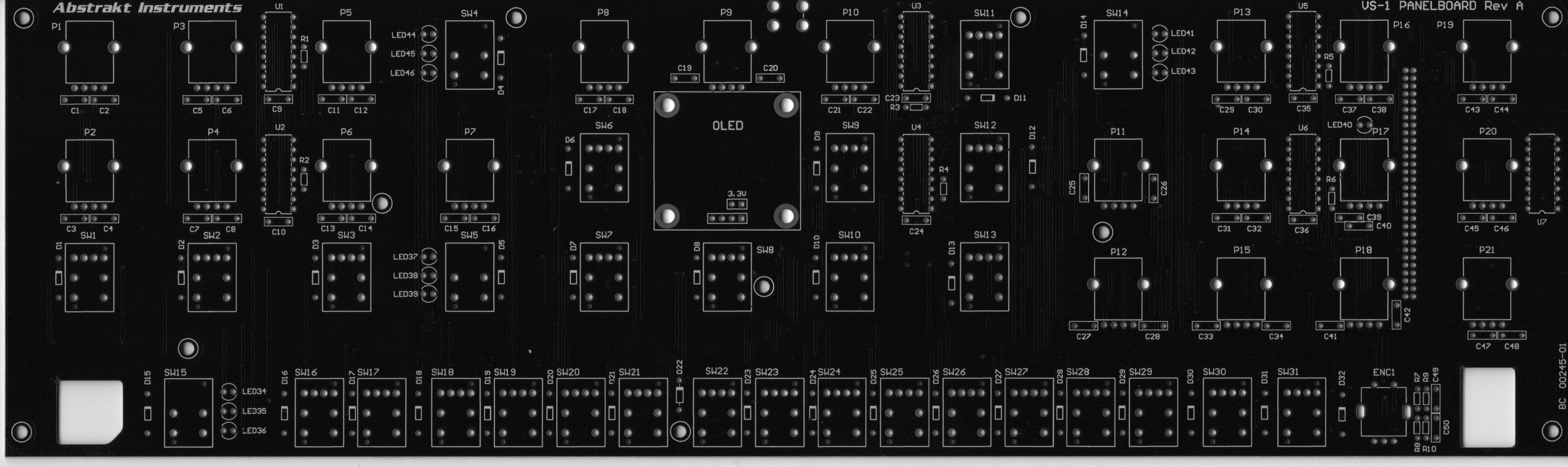
Panelboard
DAC Board
I/O Board
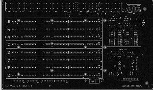
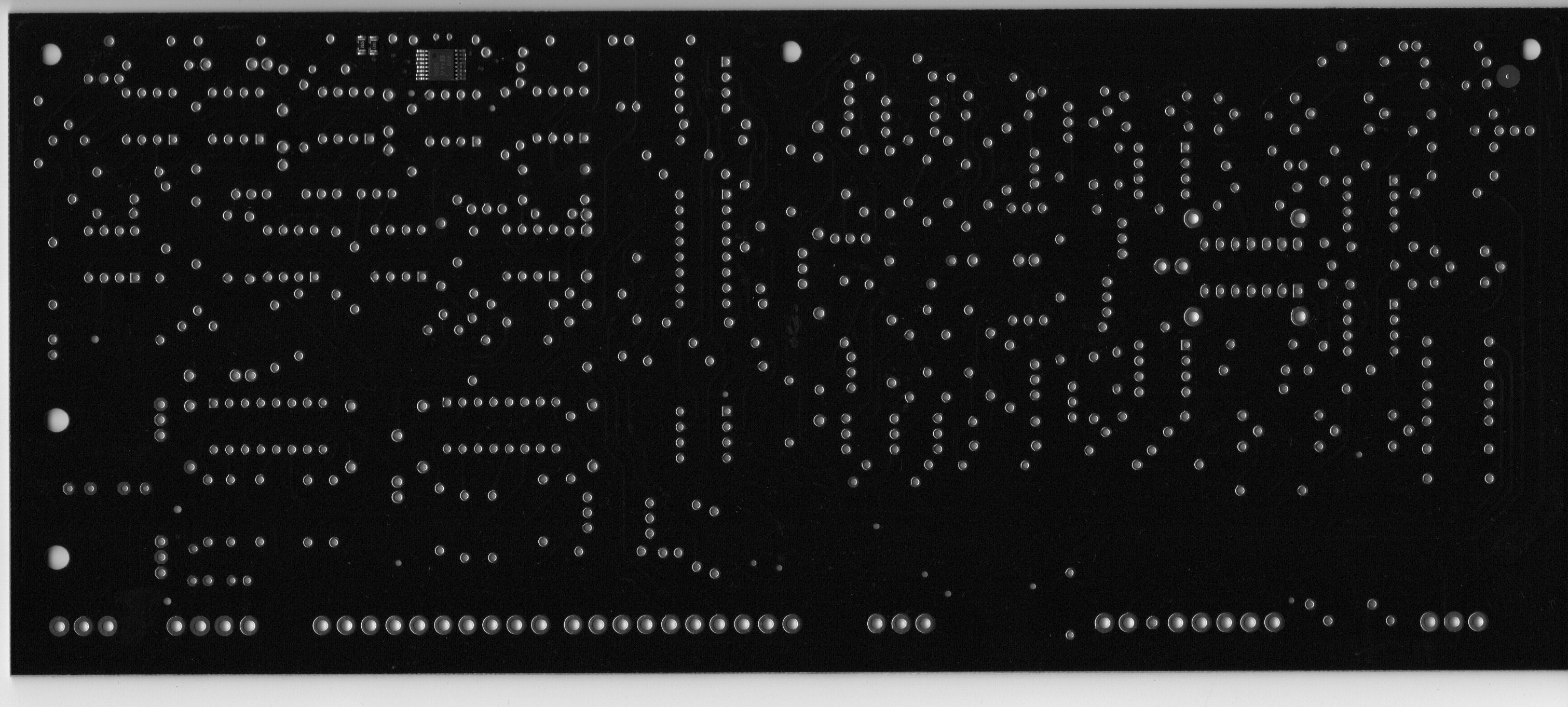
PCB Scans:
Build Manual: (official)
Please Note: The VS-1 Build Manual is still in draft form, currently draft v0.83. Formatting may change, and Section 3 on calibration is yet to be completed. There are also a few steps left in section 2 to be completed.
furthermore watch all YT videos on Brians Channel:
https://www.youtube.com/@abstraktinstruments8666
Issues/Failures/Improvements
You have to respect the Build Manual from Brian too. in case of question, contact me by Email or Facebook, Modwiggler, instagram.
| ID | Date | Bug/Issue/Improvement | affected part/pcb | Issue | Fix | reported by | reported to developer | Status/Validation QM Process | affected version | Info for the Developer only |
|---|---|---|---|---|---|---|---|---|---|---|
| 1 |
|
The Silkscreen is correct on the PCB
| modwiggler user | no | diy | this was a wrong issue !! | ||||
| 2 | 25.Jan 2024 | info | PSU | check that your PSU is still modified with other regulators my psu was still modified with the correct parts since it was bought as Partkit from Brian, back in 2020. | perform a visible check and keep in mind to test the psu later without attached Device/pcbs, as described in the YT Videos/guide. | Patrick | no | diy | ||
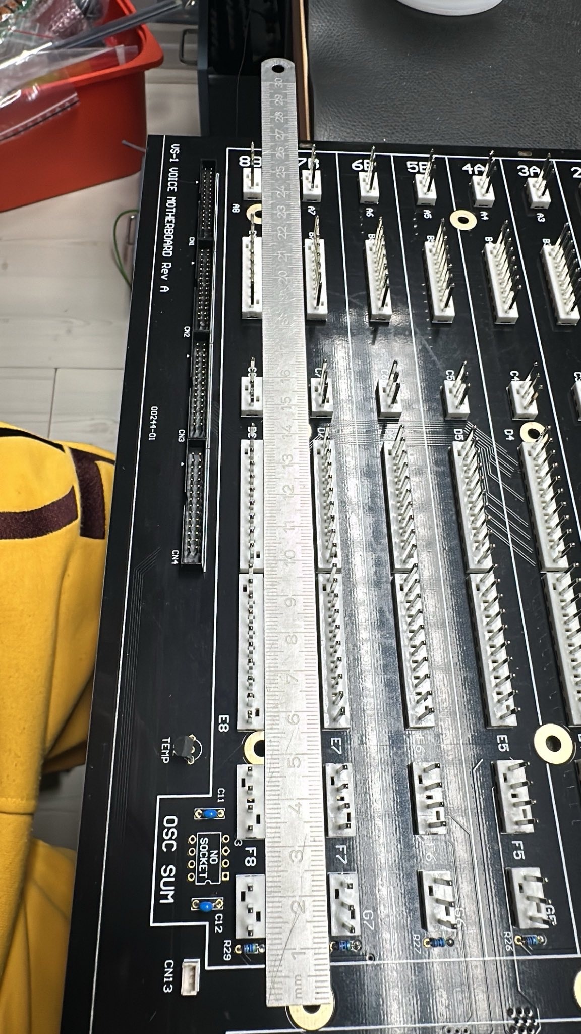
| 3 | 25.Jan 2024 | build info | Voice and Voice Motherboard | you have to respect that the MOLEX connectors on the Voice Motherboard and Voices have to installed in one step. You cannot start with soldering the molex connectors at the pcb without align it against the opposite part. do this: | It's highly recommended to use a ruler or other exact flat precisely tool to allign the Molex Pin headers in a row. This makes things easier.
| Patrick | no | |||
| 4 | 27.Jan.2024 | BOM failure | Voicecard | Voice Cards BOM lists 1.5M resistor for R7 and R45, but those are already filled with 49.9K resistors as per the BOM and the schematic | wait on validation, DO NOT INSTALL R7/R45 do not populate R7 and R45 | Stuck and Patrick | not validated now | BOM 1.0.3 | ||
| 5 | 27.Jan.2024 | Bom failure ? | Output board | On the Output board - R22 isn’t listed on the BOM, schematic says 2.2K | wait on validation | Facebook Sduck | notvalidated now | BOM 1.0.3 | ||
| 6 | 27.Jan.2024 | Info | Output board | C22 is DNP - do not populate | C22 is DNP - do not populate | Facebook Sduck | notvalidated now | BOM 1.0.3 | -- | |
| 7 | 27.Jan.2024 | BOM failure | Output Board | Q15, 16, 17, 18 aren’t listed on the BOM | is 2SC2878 | Facebook Sduck | not validated | BOM 1.0.3 | change the BOM | |
| 8 | 28.jan 2024 | info | Voicecard | "Note that R140 and R141 are the preinstalled smt resistors on the back." | Facebook Sduck | valid | BOM 1.0.3 | change the BOM | ||
| 9 | 28.jan 2024 | info | Voicecard | "Brian for some reason doesn't list parts that are back in the "Rare Parts" list, so A3 is an CA3086N; A10, A12, A13, A14, A15 are all AS3080E; and A18 and A19 are AS3310." | Facebook Sduck | BOM 1.0.3 | change the BOM | |||
| 10 | 28.jan 2024 | info | Voicecard | "There is one wrong sized hole on the bottom row of holes for the molex connectors. In one of the videos Brian suggests using a dremel tool to grind down the size of the affected pin, which I tried and it was relatively easy and worked well. I suppose you could also drill out the hole, but you would then also drill out the solder pad, and would need to run a wire jumper from the affected pin to one of the vias to make that work." | Facebook Sduck | valid | BOM 1.0.3 | Brian change on Voicecard | ||
| 11 | 29.Jan.2024 | info | Voice MOBO | 30k resistor bag is labeled with quantity of 32 - in Altium is 24. | 24 are required - BOM 1.03 correct, just the bag is wrong | Patrick | valid | |||
| 12 | 29. Jan.2024 | info | Voice MOBO | 100nF caps 20 in bag and labeled with quant. of 20, BOM is quant. of 18 and in Altium | 18 required - Bag is wrong | Patrick | ||||
| 13 | 29.Jan.2024 | Important Info | Voice Mobo | don´t remove the pcb stripes (from pcb fab - panelized pcb) in case you use a solder frame. otherwise the traces can be damaged | Patrick | valid | ||||
| 14 | 29. Jan 2024 | improvement | Voice Mobo | use 1/4W 0.5W watt 0207 Format resistors for R66/R67 to improve thermal noise | use 1/4W 0.5W watt 0207 Format resistors for R66/R67 to improve thermal noise | Patrick | ||||
| 15 | 5.feb 2024 | bug | Voice Mobo | U2 wrong silkscreen orientation | install in this way
| Patrick | valid | batch 01/2024 from kickstarter | Brian - change the Silkscreen | |
| 16 | 07.feb 2024 | Important Info | Output Board | Install R7, R11, R37, R41, R48 & R73 with few millimeter distance against the PCB to avoid Thermal Issues | Install R7, R11, R37, R41, R48 & R73 with few millimeter distance against the PCB to avoid Thermal Issues. Look in. the Buildguide | Brian | valid Yutube video and build guide | all Versions | ||
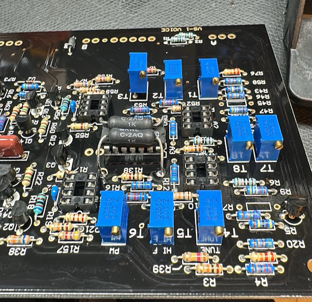
| 17 | 07.Feb.2024 | Important Info | Voice | Since we have to trim the Voices by Trimmers from Top, its not possible for 2 Trimmers when you have installed IC Sockets for A3 (Expo CA3086/CA3046) | Do not install a IC Socket for A1 in case you still installed a IC Socket, desolder 2 pins of T3 and pull the trimmer out as shown
| Patrick | valid | all Versions | ||
| 17 | 07.Feb.2024 | Important Info | Voice | Since we have to trim the Voices by Trimmers from Top, its not possible for 2 Trimmers when you have installed IC Sockets for A10 | Do not install a IC Socket for A10 in case you still installed a IC Socket, desolder 2 pins of T9 and pull the trimmer out as shown
| Patrick | valid | all Versions | -- | |
| 18 | 07.Feb.2024 | Tip | all PCBs | do not clean the Styrene Cap with Isopropyl - the Capacitor is glued and can be damaged |
| Patrick |
| |||
| 19 | 07.Feb.2024 | Tip | all PCBs | Do not wash the Trimmers, install the Trimmers and styrene Cap on Voice Card at the end and |
| Patrick |
| |||
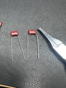
| 20 | 07.Feb.2024 | Tip | Voicecard | for better Installation and to avoid a broken capacitor due to mechanical stress bend the pins for C19 and C12 | on left original, on right bend style
| Patrick |
| @Brian change the Voicecard Pinout for C19/C12 | ||
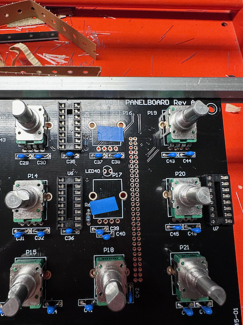
| 21 | 10.Feb.2024 | BUG | Controlpanel PCB | from my experience it can happen under Mechanical stress situation that the Potentiometer Chassis/body comes in contact thru the PCB solderstop with the traces.. This was happen on TTSH, DDRM and other devices and the users wasn't able to Troubleshoot easily the root cause ! | use a tape or other isolation on 2 Potentiometers as shown here:
|
| DIY rev.A | @Brian change the routing of the trace |
Pictures from kickstarter (link) - not for REFERENCE


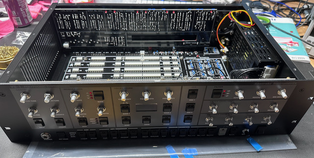
Own Pictures from my Build. Some changes aren't implemented yet . not for reference build !!