Project
Projecttitel: VS-1
Status: IN BUILD
Startdate: 06/2020
Duedate: 04/2024
Updated: 05.feb.2024
Manufacture link: http://abstraktinstruments.com
https://abstraktinstruments.com/vs1-diy/
Facebook group: (I´m the admin). https://www.facebook.com/groups/849435342474238
send me a message if you dont get access
Modwiggler Build thread:
This Pages are only especially for the DIY Version
The Kickstarter campaign is online since: 14.Jan.2020 and was sucessfully backed with 250K USD
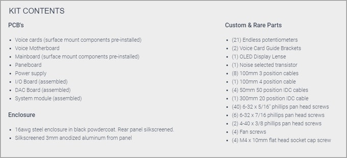
DIY PCB Set:
Stretchgoals:
- 120K - MPE Support
- 140K - Direct Outputs
- 160K - Stereo Analog Chorus - We have a hell of an analog chorus designed - we can't add cost & commit resources to implement it unless we reach certain cost targets.
- 180K SD Card
- all Stretch Goals arrived
BOM:
VS-1_DIY_BOM(v102).xlsx from 04.Jan.2024
VS-1_DIY_BOM(v103).xlsx from 24.Jan.2024
Soldercore
you need 2 solder core types:
Digikey:
- water soluble solder core, this is the solder core which you use for resistors,capacistors, IC-sockets, parts which can be in touch in water.
https://www.digikey.de/de/products/detail/kester-solder/24-6337-6403/6048
part nr.
24-6337-6403 |
Digikey:
2. no clean solder core - which must be used for trimmers and potentiometer (everything which has to be installed after you washed the pcbs with hot water)
part nr.
24-6337-8809 |
this is the old BOM and should help people to find some parts, this isn't the full BOM:
Schematics: (copy from Jan.2024)
Build it:
Please see the Altium 365 Viewer documentation for full details on the cloud-based tool.
Mainboard
Voice Motherboard
Voice Card
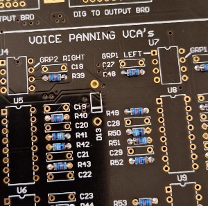
Output Board
Panelboard
DAC Board
I/O Board
furthermore watch all YT videos on Brians Channel:
https://www.youtube.com/@abstraktinstruments8666
Issues/Failures/Improvements
| ID | Date | Bug/Issue/Improvement | affected part/pcb | Issue | Fix | reported by | reported to developer | Info from developer | affected version | fixed pcb version |
|---|---|---|---|---|---|---|---|---|---|---|
| 1 |
|
| modwiggler user | no | diy | this was a wrong issue !! | ||||
| 2 | 25.Jan 2024 | info | PSU | check that your PSU is still modified with other regulators my psu was still modified with the correct parts | just a visible check and keep in mind to test the psu later without attached Device/pcbs | Patrick | no | diy | ||
| 3 | 25.Jan 2024 | build info | Voice and Voice Motherboard | you have to respect that the MOLEX connectors on the Voice Motherboard and Voices have to installed in one step. You cannot start with soldering the molex connectors at the pcb without align it against the opposite part. do this:
| do not install the molex for now on voice card and voice motherboard, ill update this issue point later | Patrick | no | |||
| 4 | 27.Jan.2024 | BOM failure ? | Voicecard | Voice Cards BOM lists 1.5M resistor for R7 and R45, but those are already filled with 49.9K resistors as per the BOM and the schematic | wait on validation do not populate R7 and R45 | Stuck and Patrick | not validaded now | BOM 1.0.3 | ||
| 5 | 27.Jan.2024 | Bom failure ? | Output board | On the Output board - R22 isn’t listed on the BOM, schematic says 2.2K | wait on validation | Facebook Sduck | not validaded now | BOM 1.0.3 | ||
| 6 | 27.Jan.2024 | Info | Output board | C22 is DNP - do not populate | Facebook Sduck | not validaded now | BOM 1.0.3 | |||
| 7 | 27.Jan.2024 | BOM failure | Output Board | Q15, 16, 17, 18 aren’t listed on the BOM | should be 2SC2878 | Facebook Sduck | not validaded now | BOM 1.0.3 | ||
| 8 | 28.jan 2024 | info | Voicecard | "Note that R140 and R141 are the preinstalled smt resistors on the back." | Facebook Sduck | BOM 1.0.3 | ||||
| 9 | 28.jan 2024 | info | Voicecard | "Brian for some reason doesn't list parts that are back in the "Rare Parts" list, so A3 is an CA3086N; A10, A12, A13, A14, A15 are all AS3080E; and A18 and A19 are AS3310." | Facebook Sduck | BOM 1.0.3 | ||||
| 10 | 28.jan 2024 | info | Voicecard | "There is one wrong sized hole on the bottom row of holes for the molex connectors. In one of the videos Brian suggests using a dremel tool to grind down the size of the affected pin, which I tried and it was relatively easy and worked well. I suppose you could also drill out the hole, but you would then also drill out the solder pad, and would need to run a wire jumper from the affected pin to one of the vias to make that work." | Facebook Sduck | BOM 1.0.3 | ||||
| 11 | 29.Jan.2024 | info | Voice MOBO | 30k resistor bag is labeled with quantity of 32 - in Altium is 24. | 24 are required - BOM 1.03 correct, just the bag is wrong | Patrick | valid - | |||
| 12 | 29. Jan.2024 | info | Voice MOBO | 100nF caps 20 in bag and labeled with quant. of 20, BOM is quant. of 18 and in Altium | 18 required - Bag is wrong | Patrick | ||||
| 13 | 29.Jan.2024 | Important Info | Voice Mobo | dort remove the pcb stripes (from pcb fab - panelized pcb) in case you use a solder frame. otherwise the traces can be damaged | Patrick | |||||
| 14 | 29. Jan 2024 | improvement | Voice Mobo | use 1/4 watt resistors for R66/R67 to improve thermal noise | Patrick | |||||
| 15 | 5.feb 2024 | bug | Voice Mobo | U2 wrong silkscreen orientation | install in this way
| Patrick |
Pictures from kickstarter (link)


