Project
Projecttitel: Swenigiser
Status: FINISHED
Startdate: 03/2023
Duedate: 04/2023
Manufacture link: https://analogsweden.com
Info:
Info
The Swenigiser is available in prebuilt and DIY Versions.
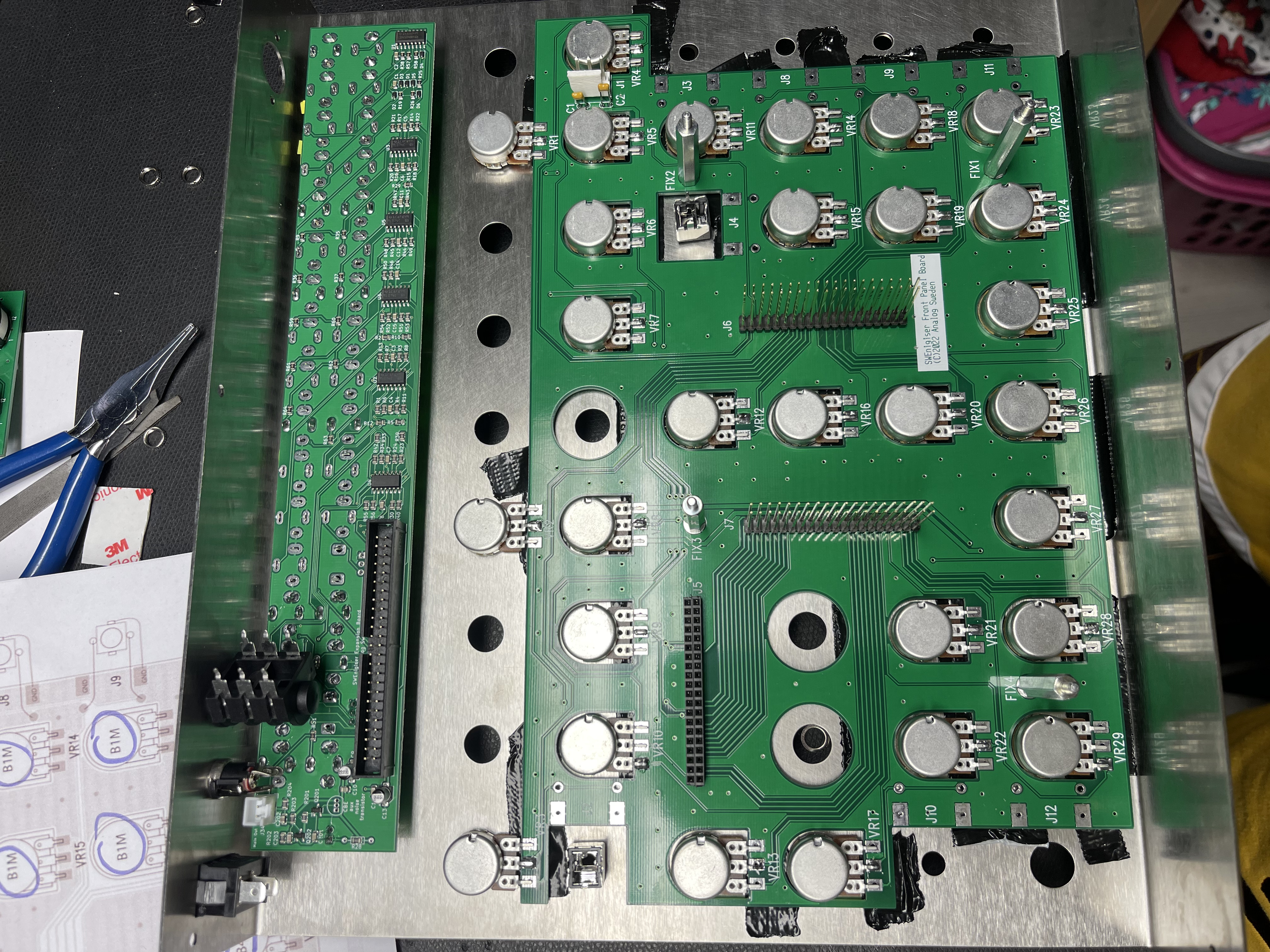
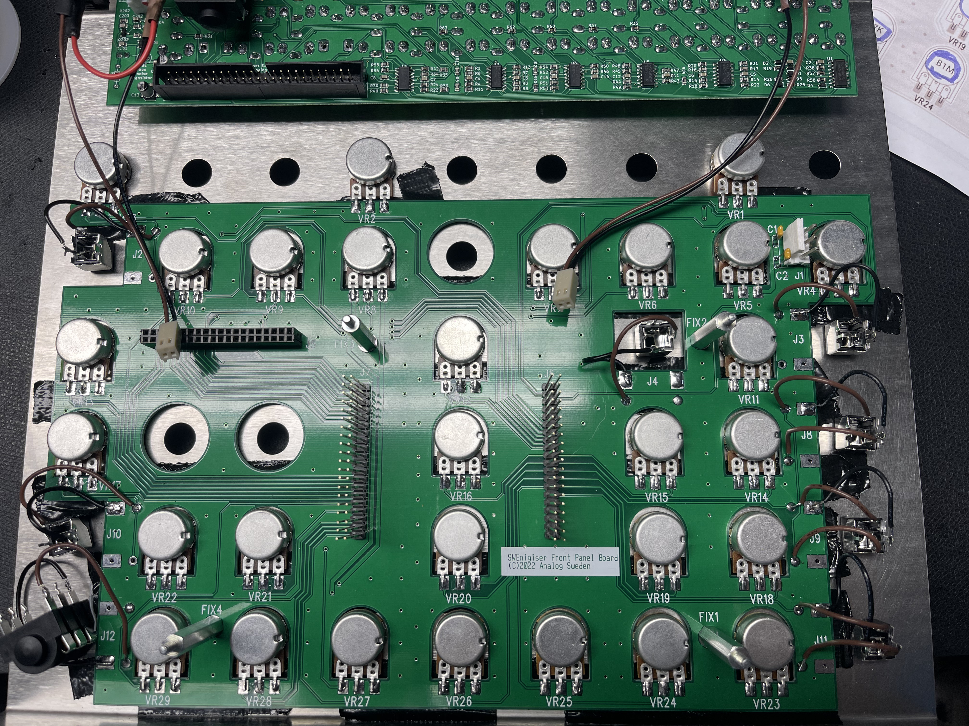
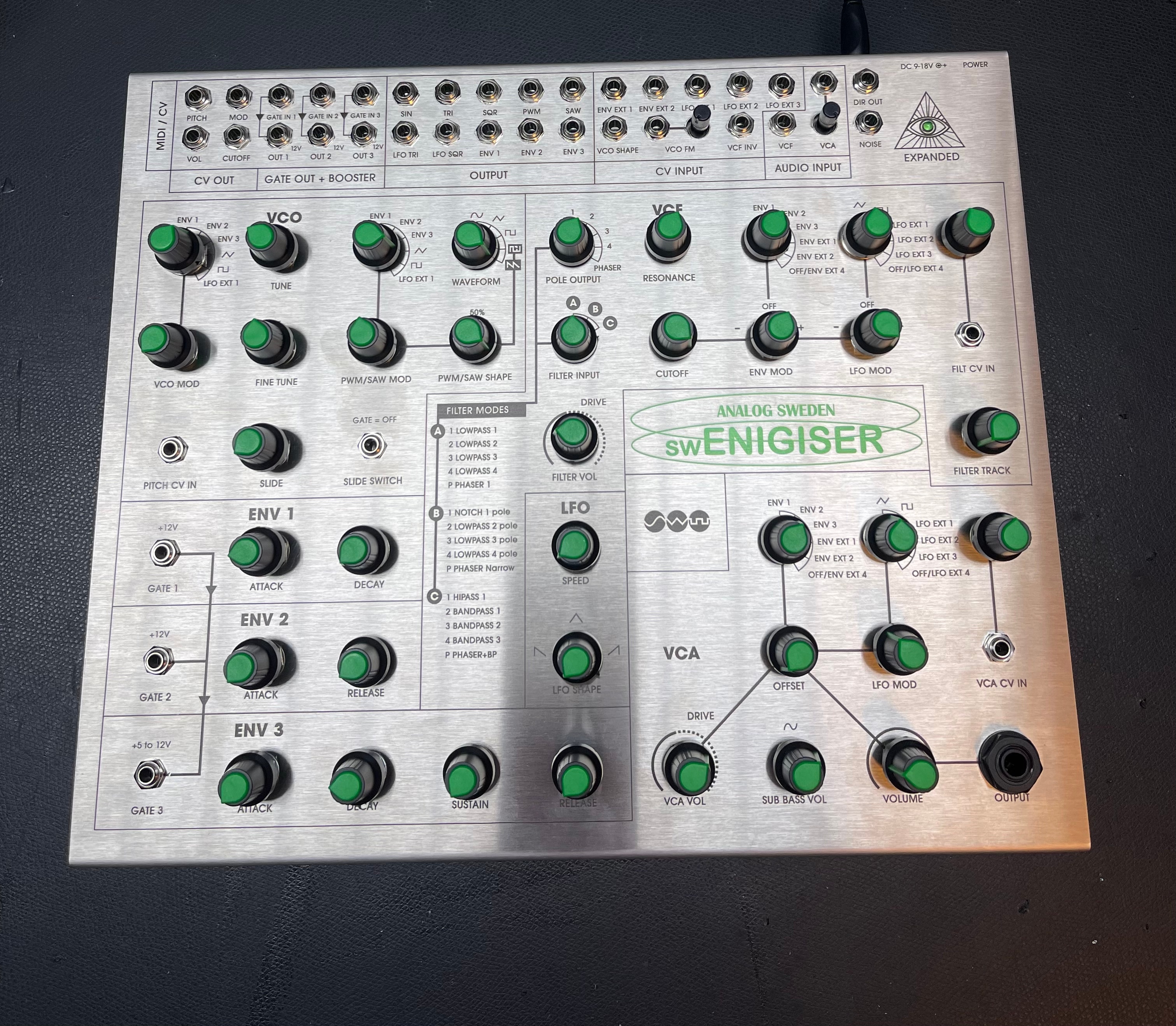
It's a fully expanded Orgon Enigiser clone - "more or less a replica", since the Voice PCB and Panel Pcbs are reverse engineered.
MIDI Input is on the rear, powerswitch too.
DIY Build Documentation
I got a PCB set, case and few parts (DIY Kit) and built the device in around 5-7hours. It was fast, because I built 2 years ago the RENIGISER clone too.
The Build is medium - not complicated and you don´t need special tools, a scope isn't required.
The most infos are described here: https://analogsweden.com/support
BOM (copy here) : SWEnigiser BOM public.xlsx
BOM notes: please read my Build tips - maybe you need some additional stuff..
Buildguide (copy here): https://docs.google.com/document/d/e/2PACX-1vT6ixpvVsDYjM1PqPgLdzOc65GO3PApa-8_ZfttzhNT1LkMXzbI6MDWRsOo-P5VEh3SpZX4UKWi19R7/pub
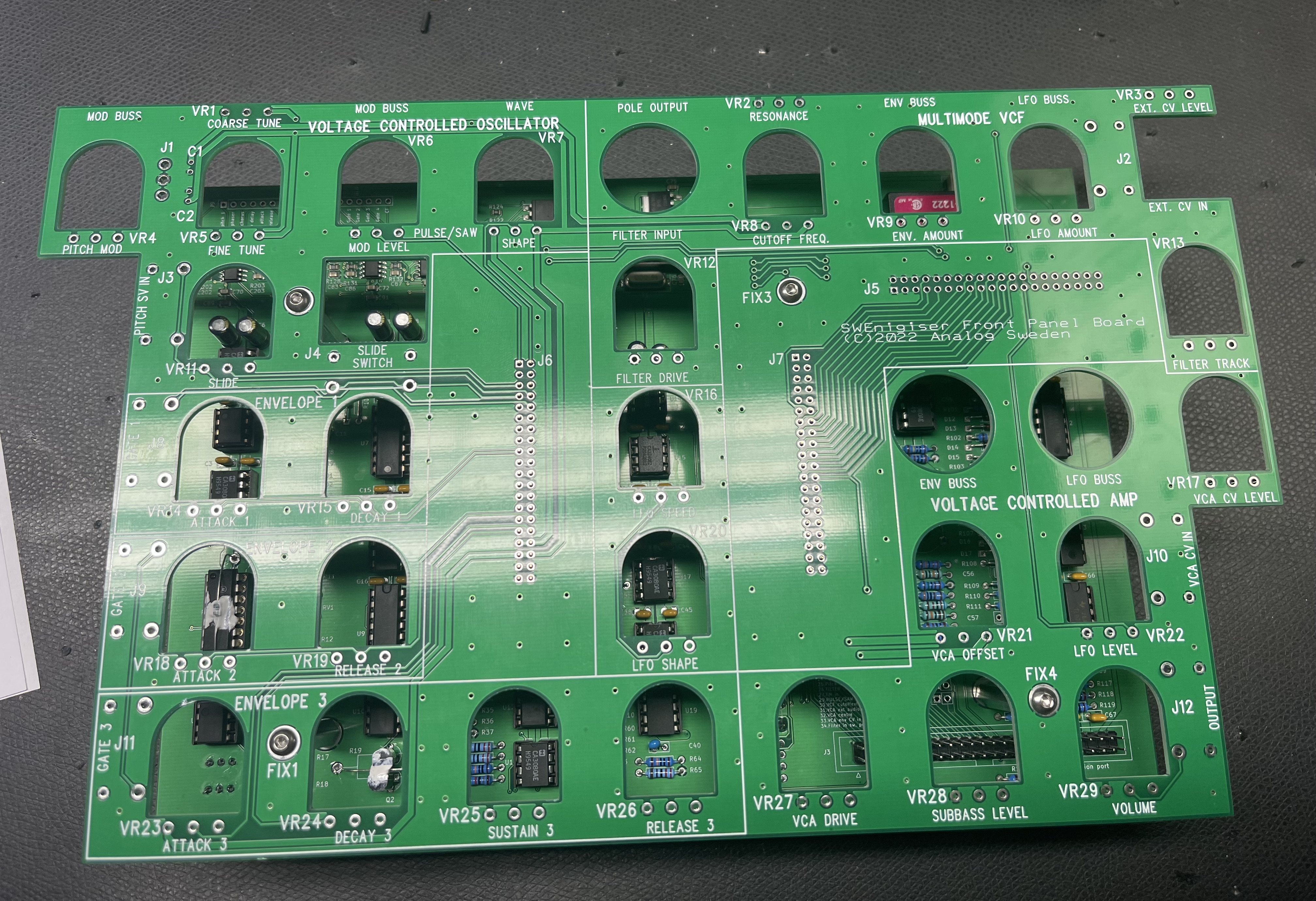
Potentiometer Guide:
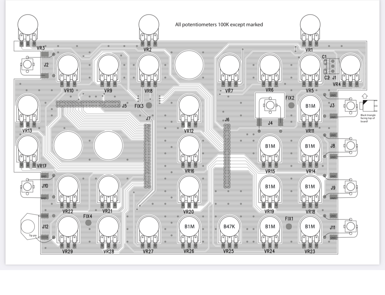
Calibration guide (copy here) SWEnigiser calibration.pdf
Usermanual (copy here): swENIG-quickstart.pdf
DIY BUILD GUIDE ADDON from me:
the biggest risk and challenge in this build:
Risks/Problems/Issues
| Issue ID | Date | Issue | Solution | affected version | Fixed version |
|---|---|---|---|---|---|
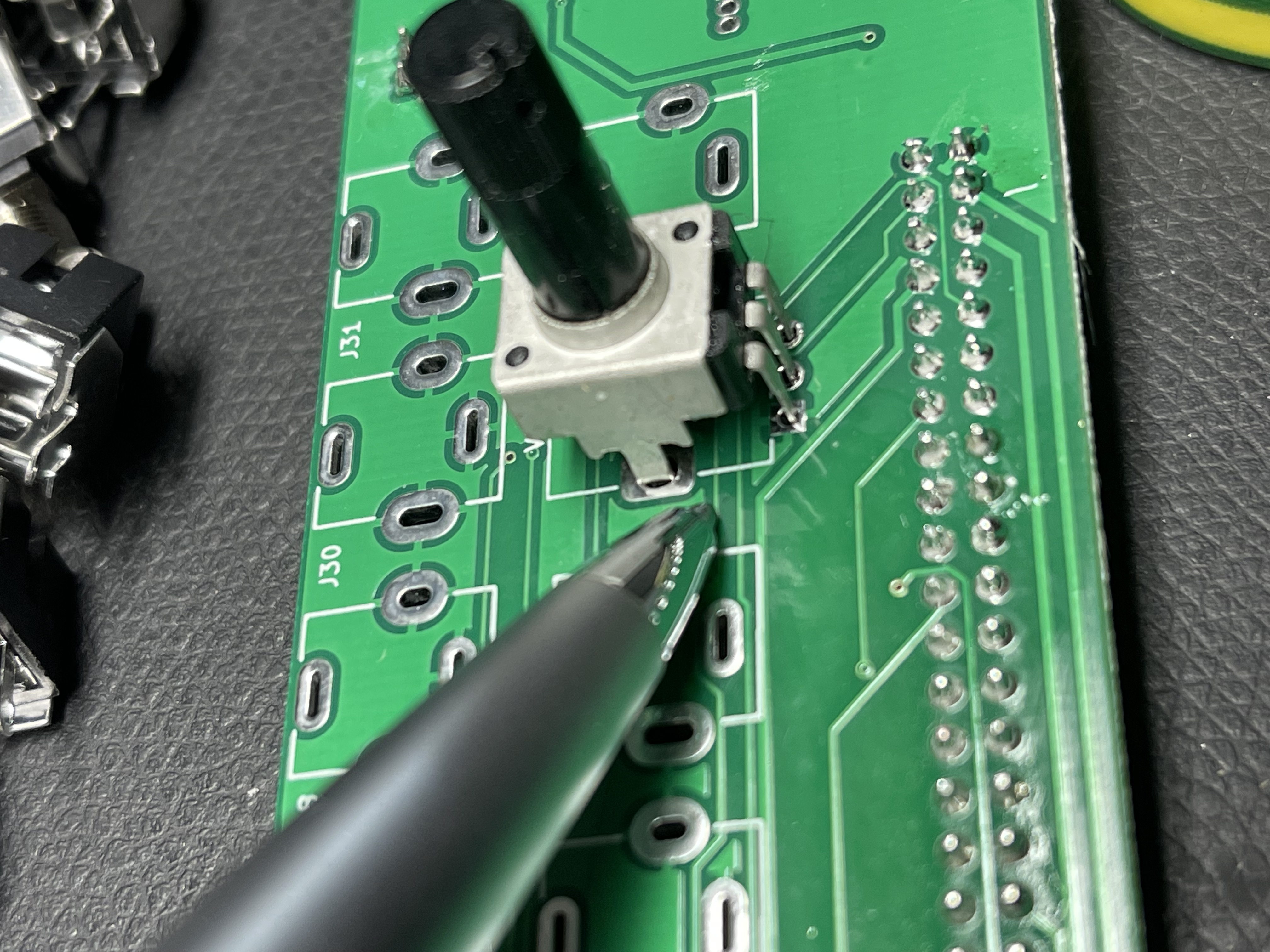
| 1 | 22.04.2023 | the panel pcb is very close to the aluminum case - its easy to run in malfunctions and defects !! Since I built the RENIGISER, I know excactly how to fix it with a workaround. | use gaffa tape and put this on the case 2 layers are fine use additional washers on the potentiometers and rotary switches to get more clearance/distance between the case and panel pcb solder all cables NOT thru the holes, just on top is fine. solder the potentiometers : add some solder on all pads !! then install the pots, use additional washers or nuts and then use nuts to fix they from outside - then solder the potentiometers. in this way you have enough space between the case and pcb with less risks. | release April 2023 | - |
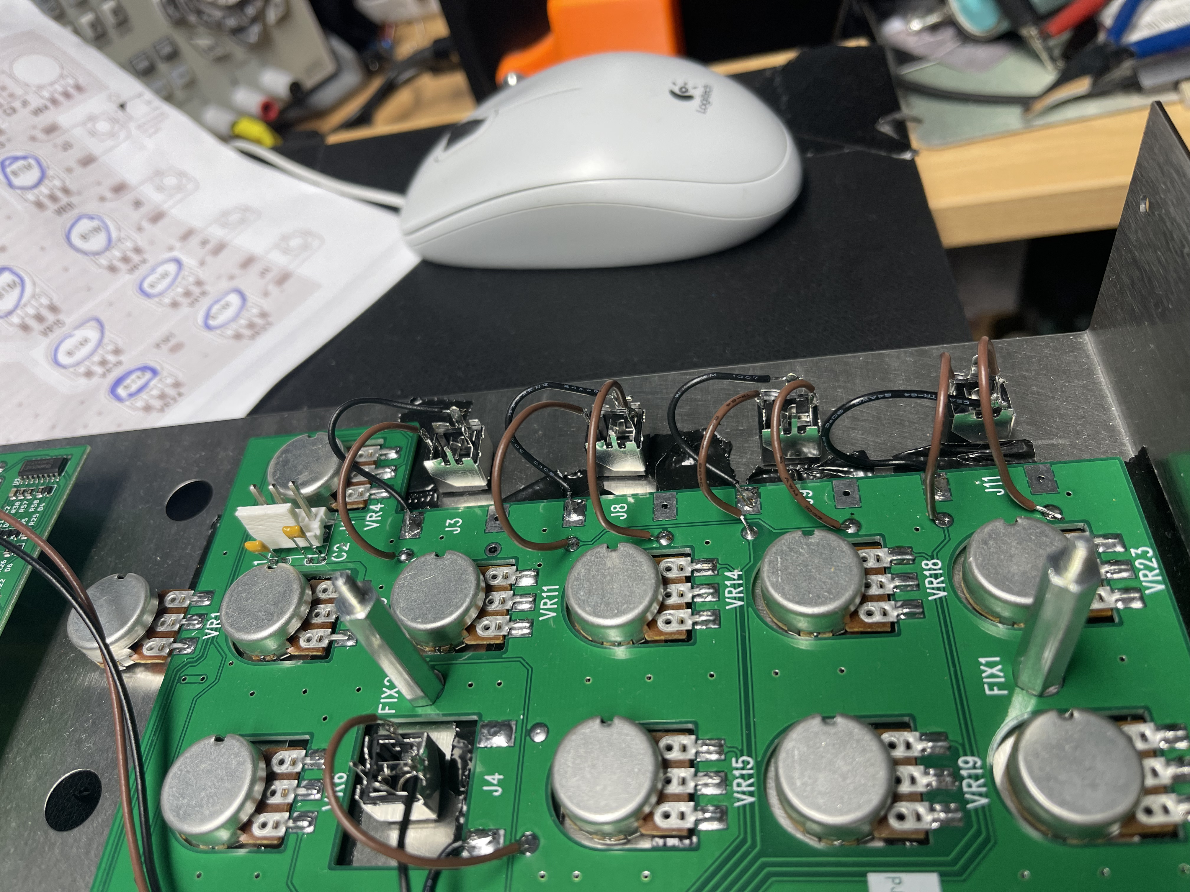
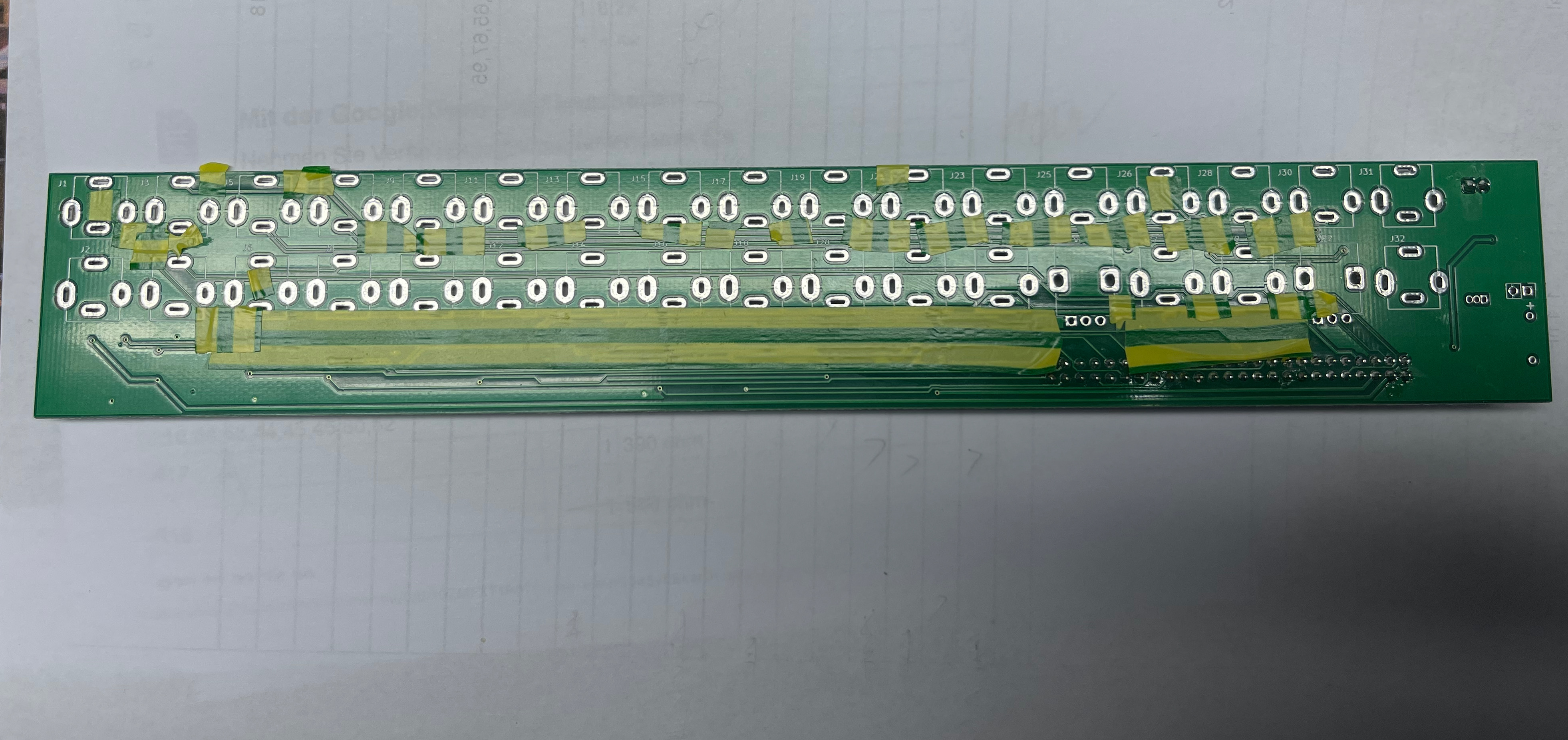
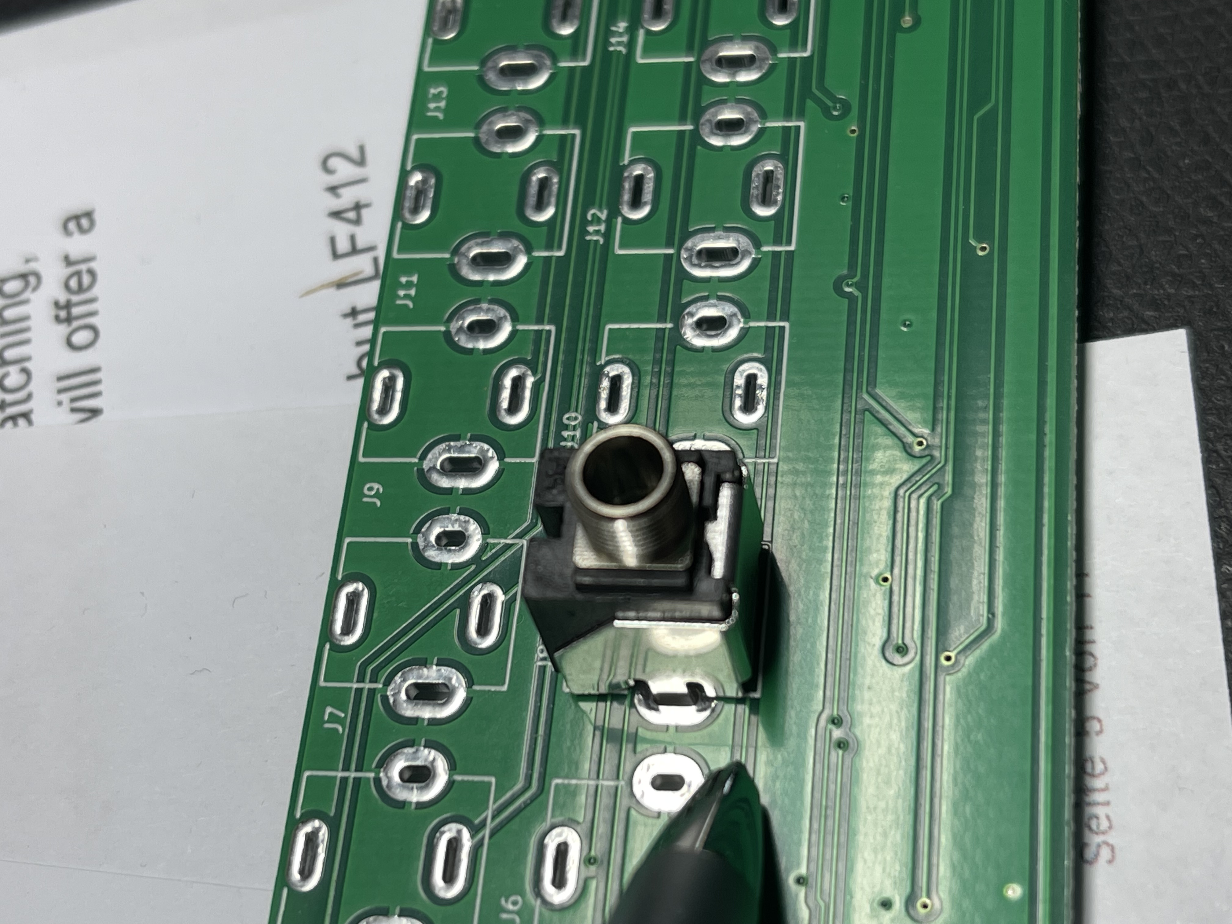
| 2 | 22.04.2023 | the Upper pcb for the jacks: a lot of traces are under the jacks and at the tall trimmer, and if you press the jacks to close on the pcb, you can damage the PCB coating - get shorts and bleeds (same was on the TTSH project and many other projects)
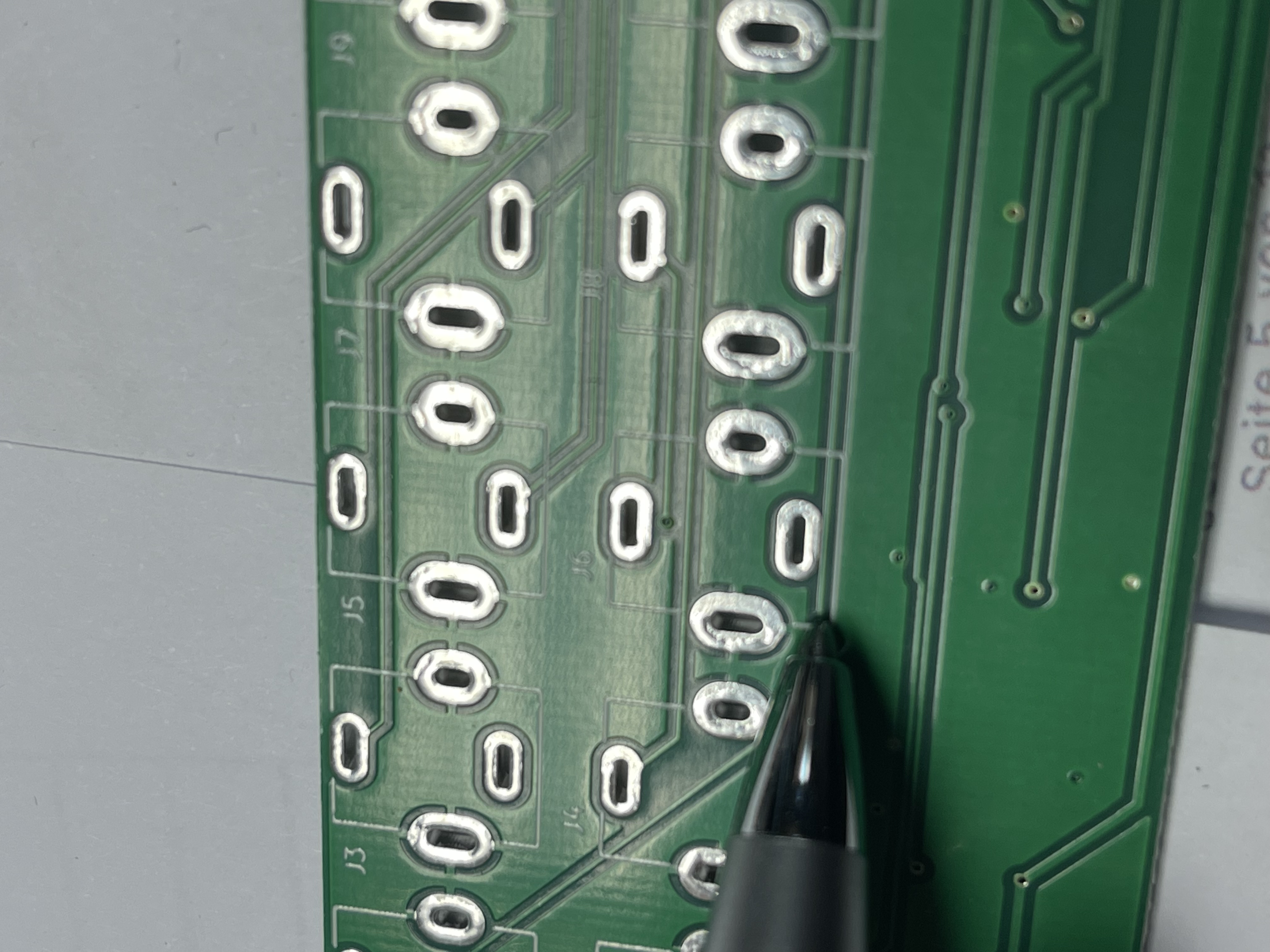 | use tape as shown in my picture and do make sure there's no mechanical stress on the jacks while soldering.
| release April 2023 | - |
| 3 | 22.04.2023 | do not forget to install the Jumpers/bridges as described in the guide | |||
| 4 | 22.04.2023 | 1pf cap | use 3.3pf or do not install a cap.. works without too | ||
| 5 | 22.04.2023 | diodes D9/D10 install this.. ( some clones and some originals dont have this.) |
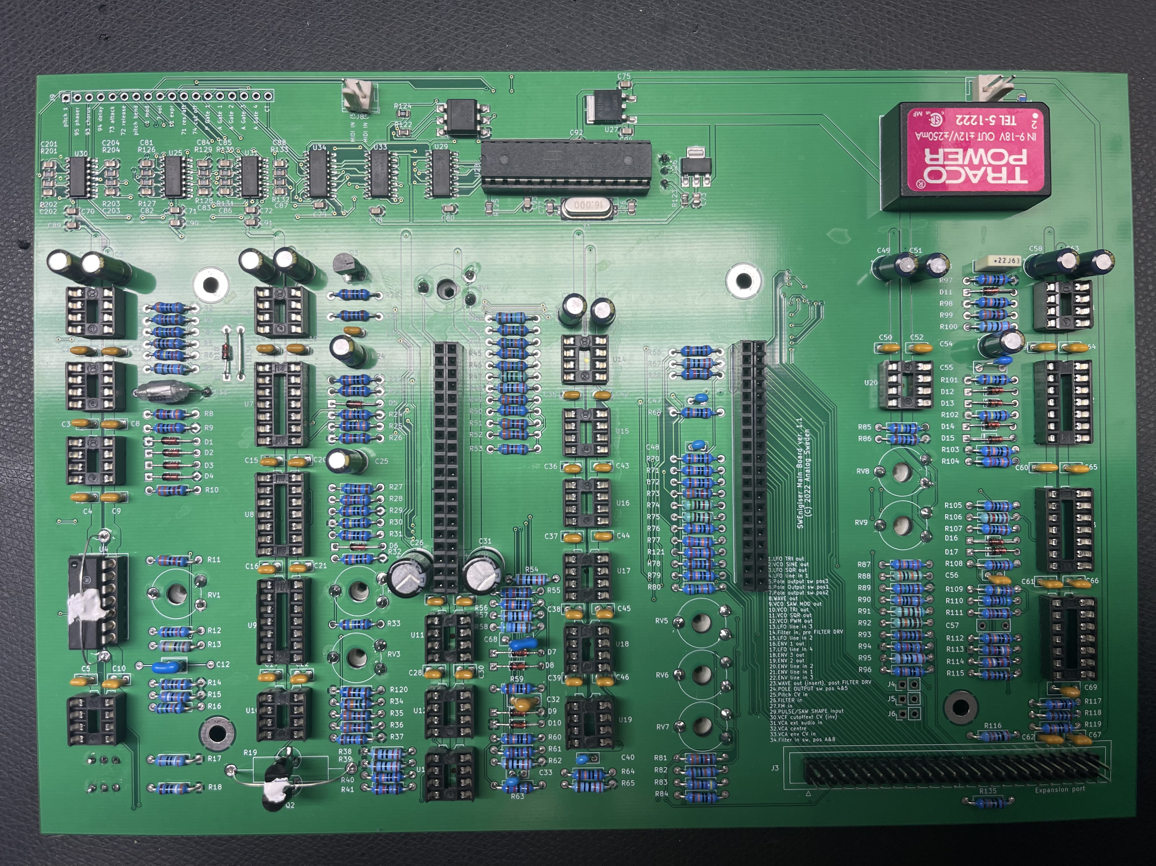
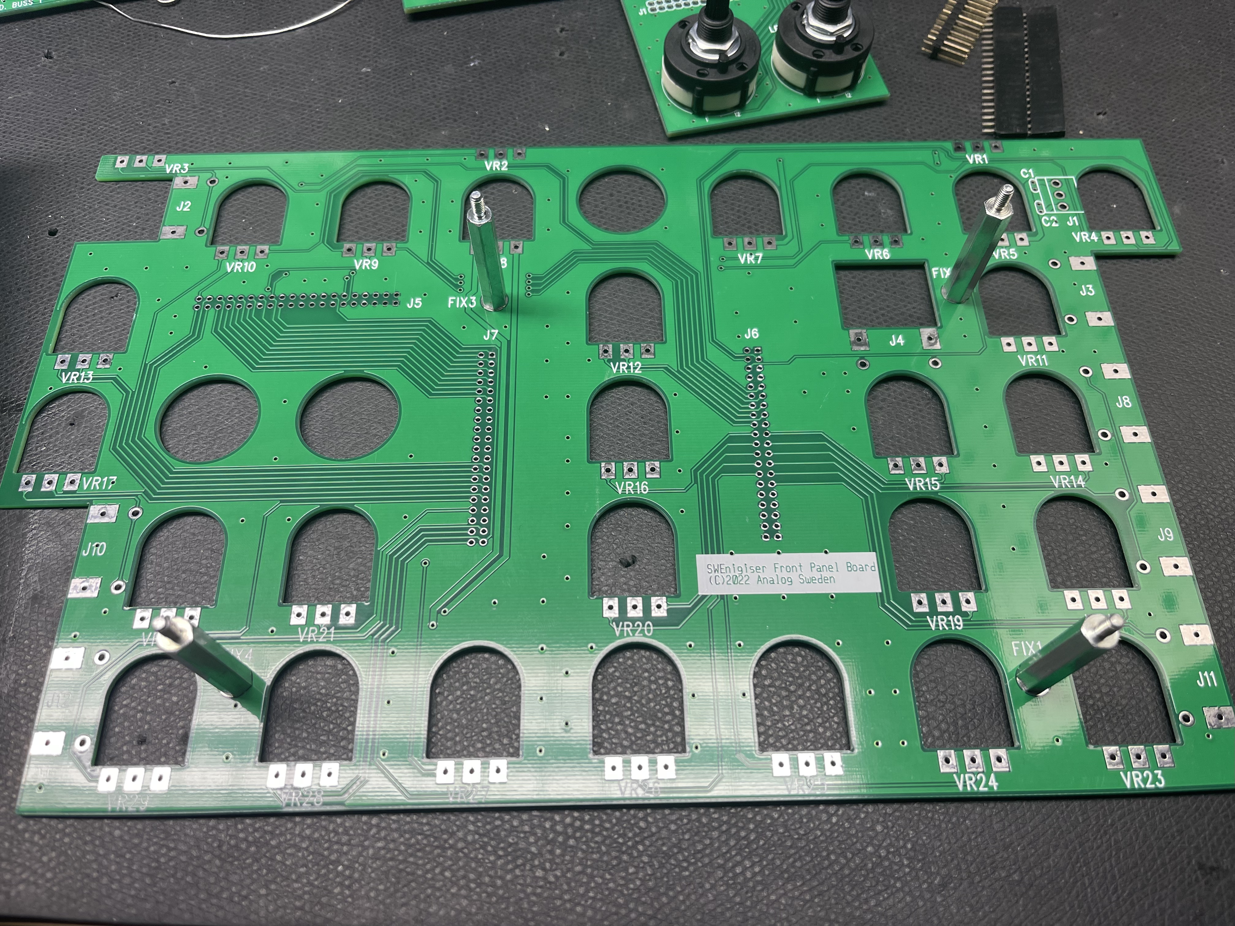
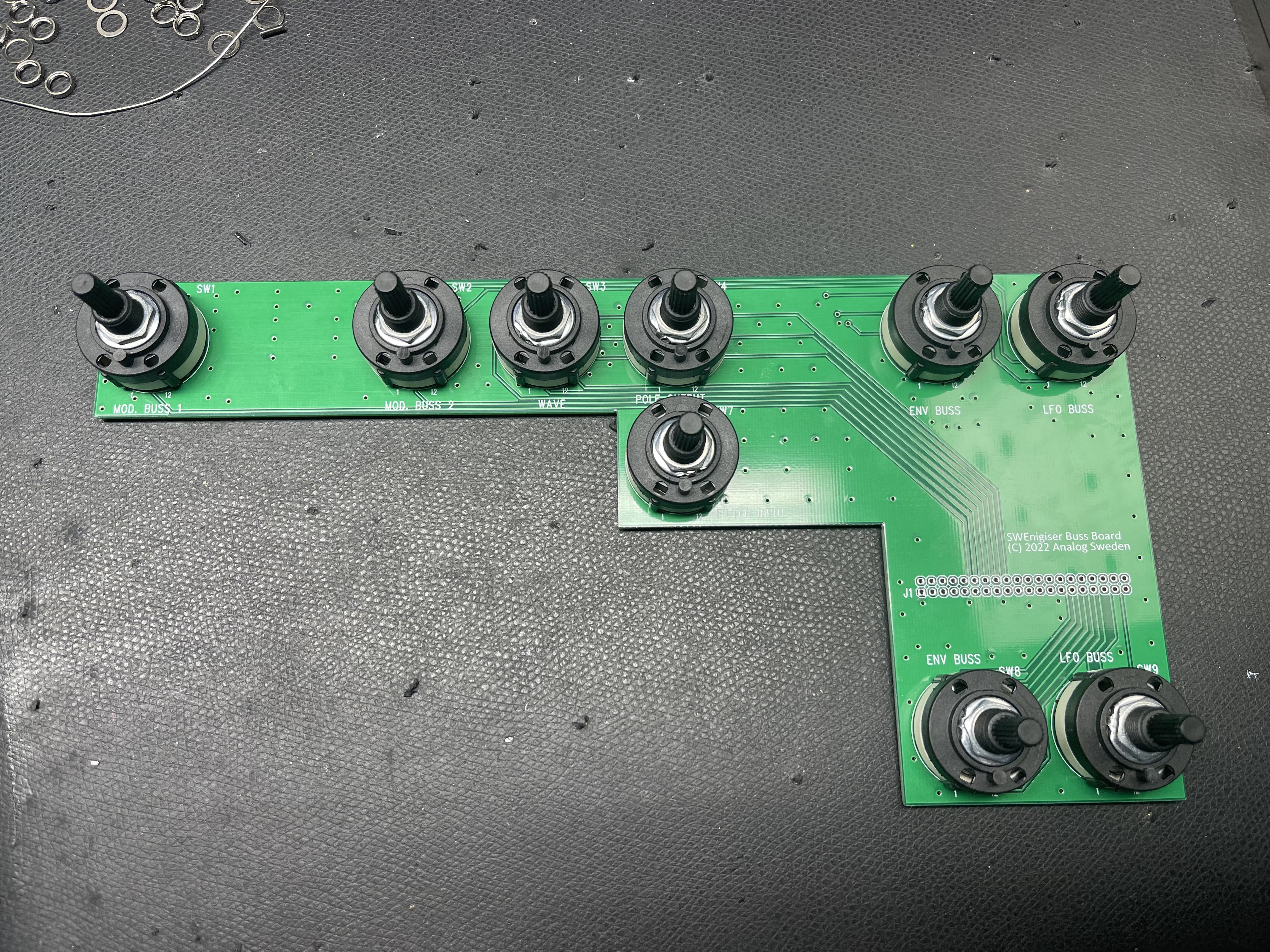
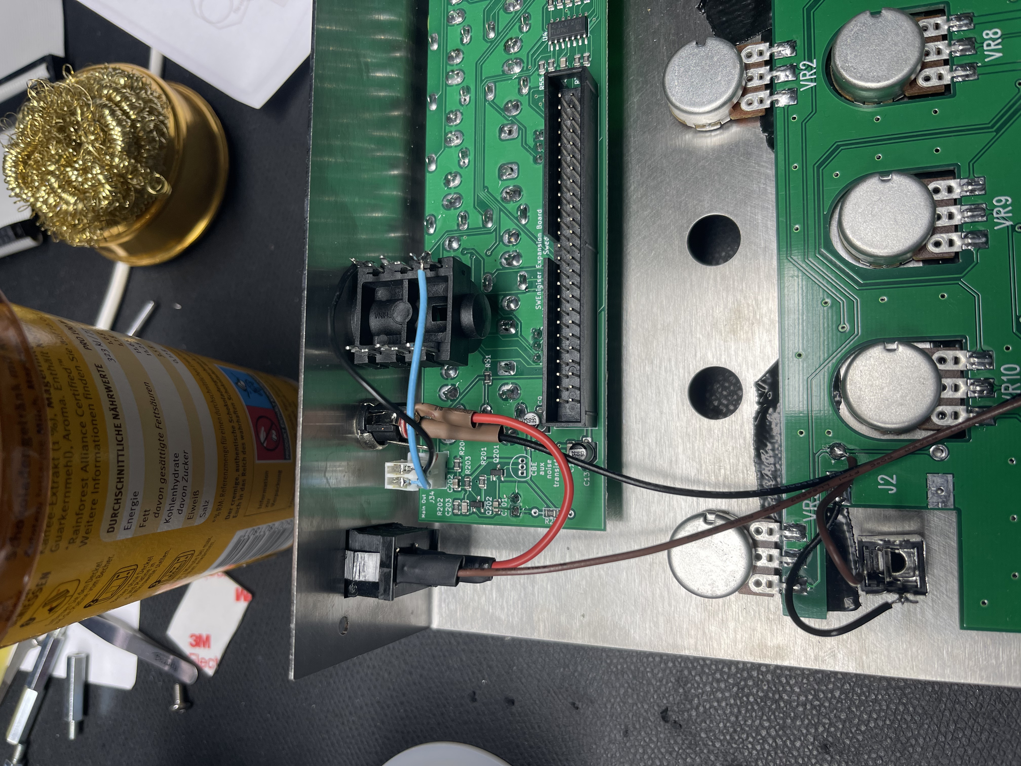
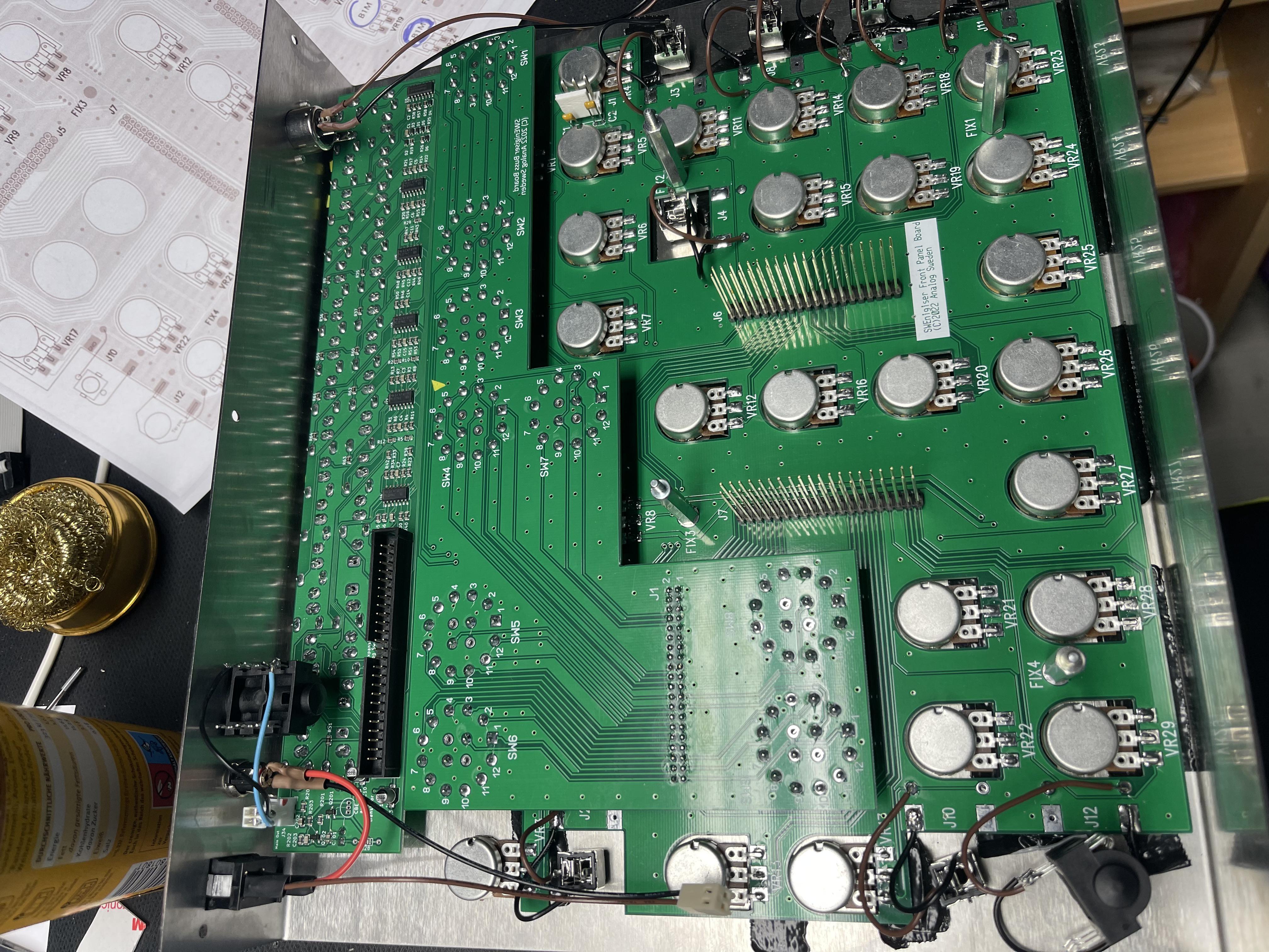
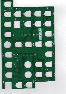
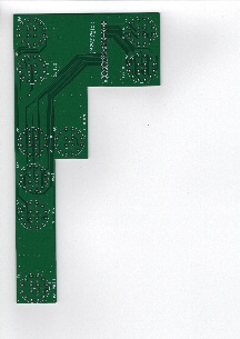
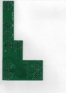
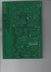
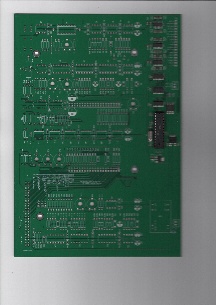
PCB Pictures:
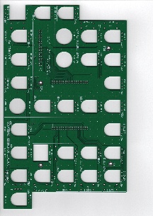
PCB Pictures assembled