DB
Project
Projecttitel:MB6582
Status: HIER ÄNDERN
Startdate:
Duedate:
Manufacture link:
User Manual:
http://www.ucapps.de/midibox_sid_manual_fp.html
before programming:
J11 (not J11_CORE1) is a 4×2 pin header which controls which Core (PIC Tx pin) is connected to the MIDI Out port. You would only need to use this once for the first upload of MIOS and the MB-SID V2 firmware, thereafter connect the master PIC (1) to the MIDI out and after uploading new MB-SID V2 firmware, the master PIC can clone itself to the other PICs across the CAN bus.
NOTE: All Cores (PIC Rx pin) are connected to the MIDI In port. The different device ID (0,1,2,3) on each PIC determines which PIC receives an upload, J11 is used to get “feedback” from that PIC during the upload.
The absolute bare minimum headers you should put in are:
J11 (for switching which Core is connected to MIDI Out)

J15_CORE1 (for master Core’s LCD)
J3_SIDx, J23_SIDx (for connecting feedback pots, or at least grounding the SID audio inputs)
Then the list of useful headers for a “default” MB-6582 setup (no expansion port usage):
J70 (for passive mixed output, to connect to headphone jack)

J2 (for power LED)
J25 (~9V-11V DC, for connecting to fan)
J3 (5V DC, for connecting to fan, if 9V-11V makes the fan too noisy)
J1_SIDx, J2_SIDx (for voltage switching between 9V and 12V per SID, see PSU Option B and D)
Then for the advanced users, perhaps wanting to connect things via the expansion port:
J6_COREx, J7_COREx (for analog outputs via AOUT modules)
J5_COREx (for analog inputs)
Check this:
Now after soldering all those, you can start soldering together the PSU section. Go back to the start of this guide and follow the soldering instructions for the PSU option you want to use. Then follow the soldering instructions for the power socket and power switch for that PSU option.
Test that the power rails and ground are not connected (shorted). You can test this at J4.
Test that each of the following IC socket's pins are correctly connected to the 5V rail:
SIDs: test pin 25 (fourth from top right); COREs: test pin 11 (eleventh from top left); 74HC595/74HC165s: test pin 16 (first from top right) Optocoupler 6N138: test pin 8 (first from top right)
Test that each of the following IC socket's pins are correctly connected to ground:
SIDs: test pin 14 (bottom left) COREs: test pin 12 (twelfth from top left) 74HC595/74HC165s: test pin 8 (bottom left) Optocoupler 6N138: test pin 5 (bottom right)
You should now be ready to plug in your power supply and turn on the power switch. It is important that you get your multimeter ready to test the voltages at J4, and test them quickly after turning on the switch, so if you don't see the right voltages, then you can turn it off quickly and avoid damaging components. If you've put the bridge rectifier and capacitors in the correct way and tested for short circuits across the power rails, then you should not have a problem.
Before connecting power to the power socket:
Check you've completely followed the soldering instructions for the PSU option of your choice, especially soldering the bridge at J71, J72 and J73 (if instructed to do so).
Check the orientation of J1A (if you are using a panel-mount socket to connect a C64 PSU). It is a good idea to test the voltages coming out of the C64 PSU first, to make sure you really have 5V and ground connected to the right pins! Ideally you should use a polarized header and connector for J1A to avoid swapping 5V and ground and destroying components!
Then connect the power, turn on the switch and:
Check DC voltage between 5V and ground at J3.
If using PSU Option A or B, check voltage at J25 (should be above 9V, around 11V depending on load).
Check output of V1 by checking voltage across C12 (bottom pin should be 9V relative to top pin).
Check 9V pin of J1_SID1, J2_SID1 relative to ground (at ground pin of J3).
If using PSU Option B, check 12V pin of J1_SID1, J2_SID1 relative to ground (at ground pin of J3).
Insert jumper into J1_SID1, J2_SID1 depending on type of SID - 9V for 8580/6582, 12V for 6581
Check voltage between pin 28 of SID socket (top right corner) relative to ground.
If these voltage checks are passed, then you have finished the PSU section and can continue. If these voltage checks fail, disconnect power immediately. You will have to work out what is wrong by testing connnections. Start with testing pins on the C64 PSU, then checking for any breaks in continuity between the power socket and the rest of the circuit, i.e. you can test if the switch is working and pins 1&2 and 4&5 are connected when the switch is on, etc.
Programming/flashing
- in case you have a PIC burner - download the file:
bootloader_v1_2b_pic18f4685.hex. (that's for the 18F4685 PIC model - not for other models)
(this the bootloader which enable the MIDI function, that you can connect by MIDI the MB6582)
if you don't have a PIC burner, ask me for a preprogrammed chip.
2. download the latest MIOS software: MIOS_Studio_2_4_8_OSX.app.zip
or for windows: MIOS_Studio_2_4_8_Win.zip
3. install the MIOS software and connect the MB6582 with your MIDI Interface to the PC/Mac - don't start it yet.
4. download the Firmware:
mios8_v1_9h_pic18f4685.hex. (that's for the 18F4685 PIC model - not for other models)
(this install the "software" in your PIC chip) s
5. start the MIOS app on your PC - and start the MB6582 - check that the MIOS tool are able to find your Core (PIC) that's an example - but its different to that what you need.
if the software isn't able to connect to your MB6582 - you get a red text warning !!
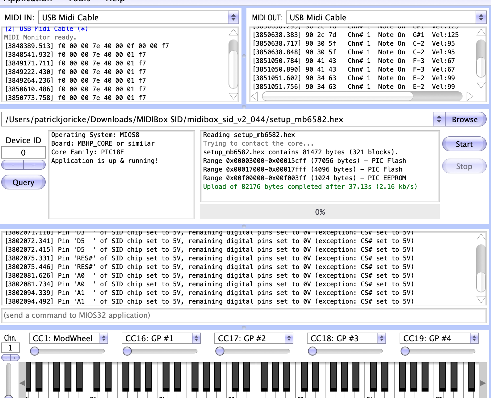
6. if the MIOS tool find your MB6582 (PIC) use the "browse" function and upload from Step 4. the firmware and press "start".
7. you will see that your MB6582 starts acting on the Display and the LEDs comes to life.
if the display stays dark or don't show text, turn on the MB6582 the 2 trimmers close to the PIC chip (contrast and brightness)
8. download the "application" this is the "player/editor" of the synth. there are some other apps on the ucapps website too (test tools)
setup_mb6582.hex. (this file works for all SID chips !!)
9. install with the MIOS app the setup_mb6582 file
that's it.
leave a comment or contact me in case of questions.
Build infos for myself:
Control surface build:
http://www.midibox.org/dokuwiki/doku.php?id=wilba_mb_6582
Base PCB build:
http://www.midibox.org/dokuwiki/doku.php?id=wilba_mb_6582_base_pcb_construction_guide
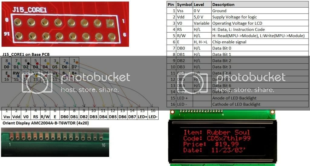
Display:
http://midibox.org/forums/topic/14564-building-the-mb-6582-control-surface-photo-tutorial/
I used the 2004A model:
Pinout
| number_marked_on_Display | ||||||||||||||||
|---|---|---|---|---|---|---|---|---|---|---|---|---|---|---|---|---|
| Display PIN | 1 | 2 | 3 | 4 | 5 | 6 | 7 | 8 | 9 | 10 | 11 | 12 | 13 | 14 | 15 | 16 |
| Display Function | VSS | VDD | V0 | RS | R/W | E | DB0 | DB1 | DB2 | DB3 | DB4 | DB5 | DB6 | DB7 | BLA(+) LED + | BLK(-) LED - |
| on Mainboard: | 11 | 12 | 13 | 14 | 15 | 16 | 8 | 7 | 6 | 5 | 4 | 3 | 2 | 1 | 9 | 10 |
| check |
Mainboard:
| 1 | 2 | 3 | 4 | 5 | 6 | 7 | 8 | 9 | 10 | 11 | 12 | 13 | 14 | 15 | 16 |
|---|---|---|---|---|---|---|---|---|---|---|---|---|---|---|---|
| D7 | D6 | D5 | D4 | D3 | D2 | D1 | D0 | B+ | B- | VSS | VDD | V0 | RS | RW | E |
after programming:
LED resistors R40-R55 (220R)
Todos after build:
What's the purpose of the J70 header?
This is a passive mixed output of the four stereo channels, which you can connect to the small phono jack above the power switch. Totally optional.
This was a late design idea I threw into the prototype, the resistors below each audio socket are used to connect the audio signals together when there is no plug in the switched audio socket, i.e. it will only mix those sockets without plugs. You need to connect it together with insulated wire under the board though…. I didn't want to mess up the ground plane with tracks. To the right of the resistors R70-R77 (below the stereo sockets) are pads, these pads should be connected in two sets of wires, one set connects the pads that are next to R70, R72, R74, R76, the other set connects the pads that are next to R71, R73, R75, R77. (NOTE: R2 boards do not require the wires, there are tracks on the top layer.)
I used 10K resistors there because that's what I've seen before in passive mixer designs, but the output is very attenuated, and I am guessing that you could drop these to 1K or less, as the outputs of the audio buffers after each SID can probably handle that. Someone with more audio electronics (and SID!) knowledge can probably answer that question.