ISSUE:
both Filter dont work as designed, a addionaly pot controls Spread
in both Channel some LP/BP dont work.
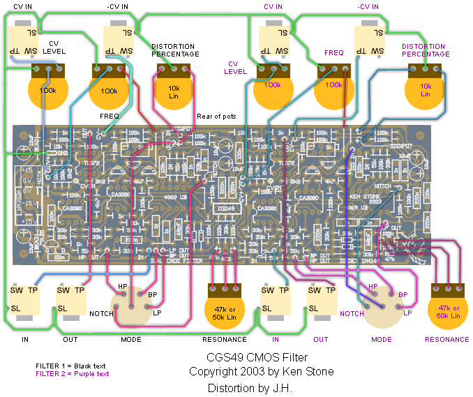
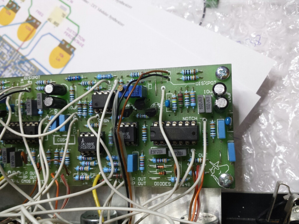
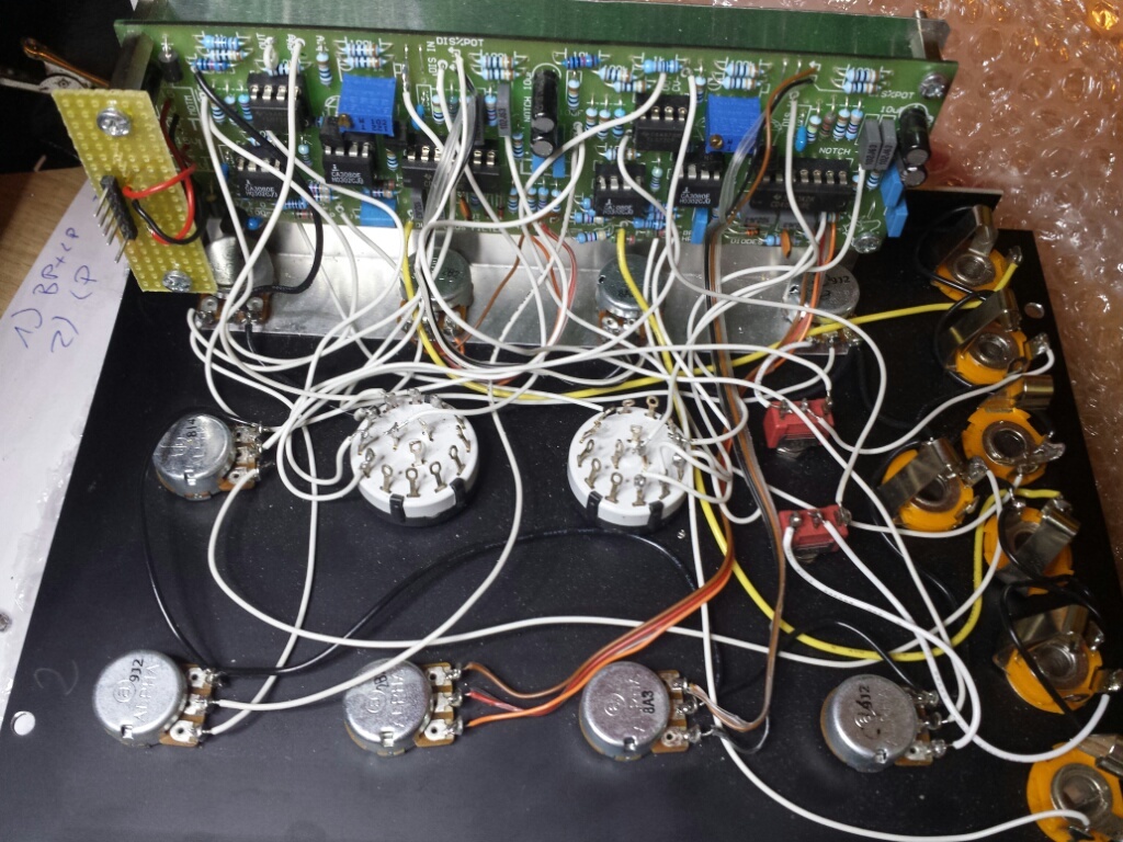
here the panel of the defective module (copy from scott - bridechamber)

Website:
http://www.cgs.synth.net/modules/cgs49_twf.html
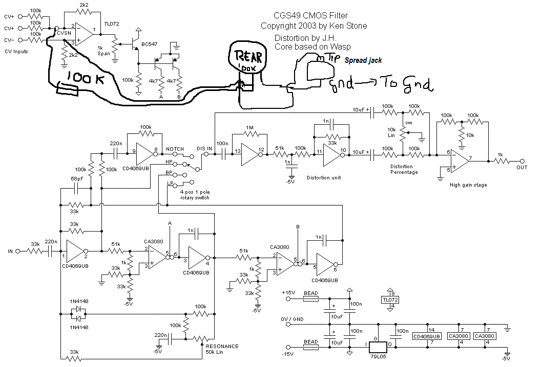
Technical:
Controls:
- Frequency - sets intial filter frequency
- Freq CV 1- Attenuator for CV in 1
- Resonance - controls amount of filter resonance
- Distortion - Mixes in post filter distortion effect
- Filter Mode - selects lowpass, bandpass, highpass and notch modes
I/O:
- In - audio input to filter
- CV 1 input - filter frequency input with attenuator
- CV 2 input - filter frequency input
- Out - filter output
Troubleshoot info:
"did the RTFM-thingy on Ken's website and connected the frequency pot to +VE / -VE and added a 150K restistor in series ... as mention on the website " found on electromusic.com
What connection would you make to the ccw position of the potentiometer in place of gnd to wire it between +/-V?
If you mean "how do you wire the frequency pot so that it gives a wider range, going lower than the frequency obtainable with the CCW end of the pot wired to earth", the answer is you wire it to -VE. If that gives you too much range, put a resistor between the CCW end and the -VE rail. 47k would be a good starting point.
This is just a guess, but the wiper of the Spread CV pot might be normalled to the CV input of the first filter and the Inverted CV input of the 2nd filter.
That way it would work as a 'spread'...?
You would wire the Spread CV jack to the input of the Spread CV Pot. Then the Wiper of the Spread CV pot would go to the switched inputs of Filter 1 CV input and Filter 2 inverted CV input.
Oh and of course ground to the 3rd lug of the Spread Pot and the Spread jack.
A 100k Pot like the other CV inputs will be fine
from Scott:
Sorry for the lack of documentation on that. You use the switch for the inversion of the CV. The spread pot is an attenuator (100k is good) for the spread jack. From the wiper of the pot, send one wire to CVSN on filter A via a 100k resistor, and one to the junction of the 100k, 2k2 and pin 3 of that TL072 (where the negative CV is going) of filter B. This will apply the spread voltage positively to filter A and negatively to filter B.
user:
I took some advice and wired the frequency pots +V and -V instead of +V and Gnd. The filter works fine now. I'm going to experiment with limiting the range of the frequency pots.
TEST CASE 1:
with layout for Spread source are the infos above.
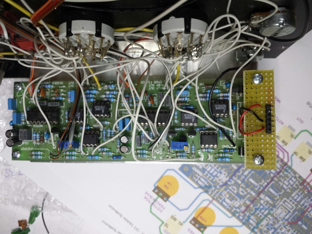
in the defective device, the 100k is missing.
picture: Failure 1, no 100K resistor from spread pot to CVSN

Failure 2: frequency pot is connected to GND, but must connected to -VE
a copy of ken stones page: