Project
Projecttitel: TTSH rev3 buidling guide
Status: IN PROGRESS
Startdate: 15.Dec.2016
Duedate: 31.Dec.2016
Manufacture link: http://thehumancomparator.net/
This guide isn´t complete yet, i still work on it. ( last update on 22.Dec.2016)
open tasks:
- LED-man add a trusted builder list
- give trusted builders write permissions here
BOM: (Bill of material)
the shared mouser basket from thehumancomparator is wrong (22.Dec.2016)
(this Mouser basket was provided in the ordering eMail)
https://www.mouser.de/ProjectManager/ProjectDetail.aspx?AccessID=234c0 9ed60
delete from this mouser basket both parts:
652-SRN6028-101M
710-744290321
this chokes/filters aren´t needed in rev.3
printabel BOM as list, (rev.2 plus additional list for filter and psu)
ttshv2BOM.pdf (mainboard pcb)
4027v2BOM.pdf (vco boards)
TTSHrev3_SecondFilter_BOM.pdf (filter board)
known issues:
- Powersupply Board - turn the 2pol MTA156 header if needed - otherwise the power input cable is above the powersupply.
 confirmed
 - Main board – Missing trace from V- to header. (copyright of picture for thehumancomparator.net )

- 4072 VCF missing trace pin 4 on LM1458 to -14V
- 4012 VCF Board — BC558 should be installed backwards
buildguide:
This guide is for users with experience in SDIY, you need a scope and a frequency counter, DMM/DVM/LCR-Meter)
i dont share infos about polarity of capacitors, this basics skills are required, otherwise feel free to ask me for a assembly service. (check the trusted builder list)
please use a fume extractor.
its needed to solder 6 SMT caps in 0805 format and 2 SMT power regulators.
this guide is a best practice guide, i´m not responsible for failures/malfunctions/defects.
- lets start with the powersupply board - add all needed parts on the pcb, start with the two SMT power regulators.
there is one missing part (a dual choke) - please use wire links here or resistor legs
turn the 2 pol MTA header as described in the picture
if needed - wash the pcb carfully on the solderside
testing/trimming: use a 18-24V DC powersupply for input and set the output to 15V/-15V by usage of the both trimmers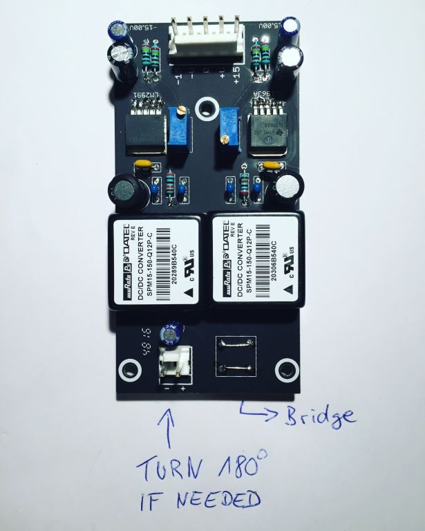
- Mainboard PCB - place all IC-Sockets ( tin one ic socket from top, place the ic socket and heat the ic socket pin - the socket drop in place
best practise - begin with the "most use values" and end with the value range Mainboard PCB - start with 100K resistors, 10K, 1K, 1M, 100R (reverb), 10R (Amp) 10M (top right)
if done - 47k, 4k7, 470K, 4M7, – 22K, 220K, 220R, 2M2, 33K, 3M3, 330K... — 30K1, 680R, 68K, 68K1, 680K... ..... and all other
please remember: on solderside are few resistors too - on VCO 4027 boards and filter boards too - its your choice to leave it for later or assembly it yet too (i prefer later) - Mainboard PCB - place all rectifiers 1N4148
- solder from top all parts
- cut the resistor and rectifier legs from bottom side
- place all MLCC caps and solder from top
- place all polyester/polypropylen caps - bend the legs from top
- add all transistors in place and solder one pin from top -(except the 2N3954, both 2N3958 - if you cant test this, use a milled IC-socket and cut the pins out - use this as socket)
- turn the pcb and solder all pins. (no switches, no fader, no jacks, no pot, no trimmers)
- you find on solderside few resistors
- wash the pcb 2-3 times if needed, i use Ispopropylen alcohole
- make a break yet - the pcb needs time to dry - if you dont need a break - assembly the filterboards and 3 VCO 4027 boards - wash them too, make sure you use flat 10uF electrolyt capacitors, use c0g, polypropylen or silvamica for the 680pF cap, dont mount the connectionsheaders yet
- Mainboard pcb: its time to add all other parts on the pcb - i prefer multiturn trimmers for the VCO V/oct trimmers 20K or 25K, but remember this can´t mounted on the frontpanel pcb side due to sizing, you have to open your TTSH for trimming the VCO
begin with