The Psu PCB is available in my shop:
I reworked a PSU design, because the most bipolar psu pcbs doesn't match with my requirements.
...
Inputs and Outputs are mechanical very stable and the pcb can be attached by 6 Screws.
a DPDT switch connect/disconnect the power (a standard MTA156 4 pole header is used here)
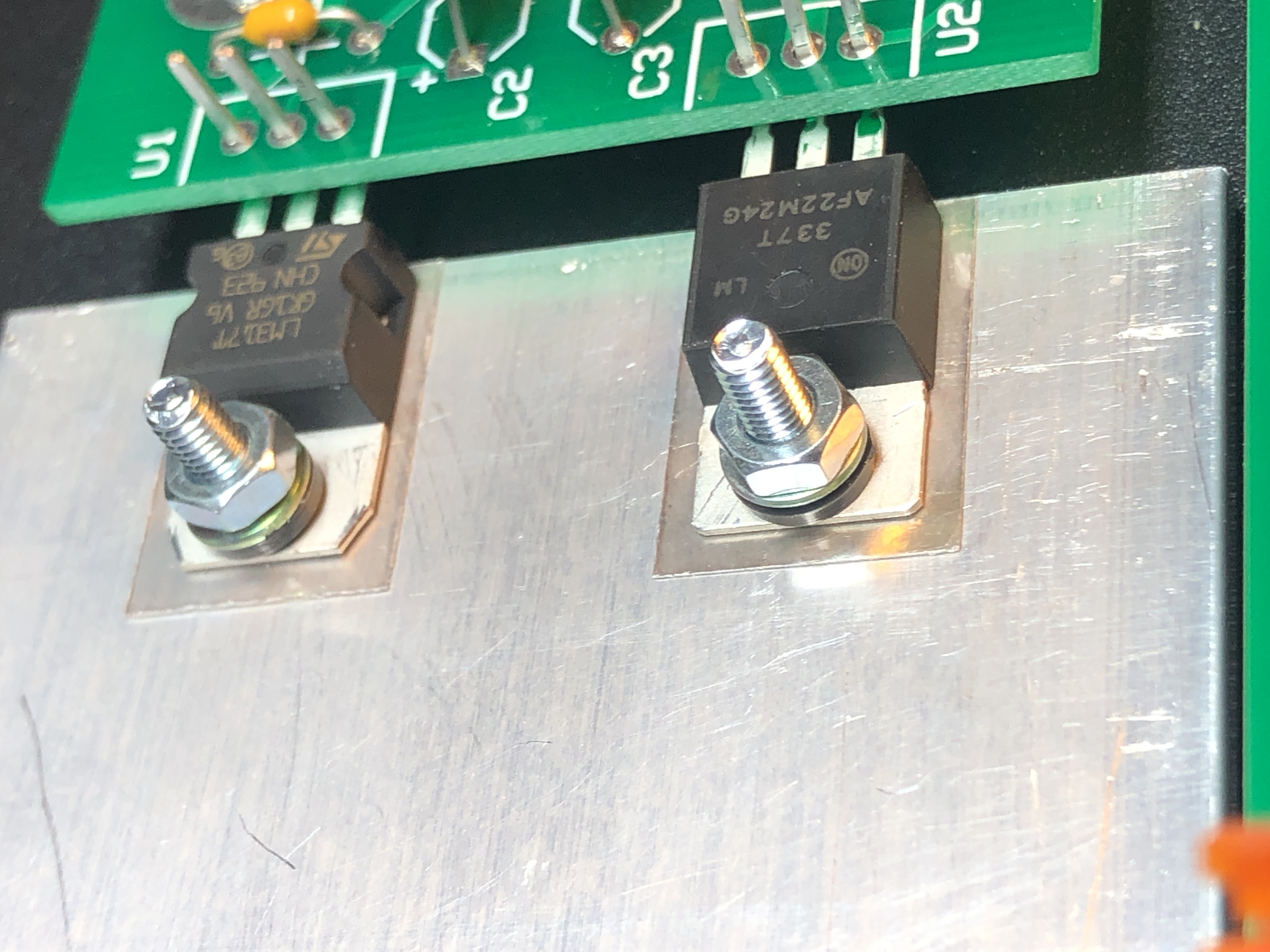
The Voltage regulators can be mount directly (with isolation/glimmer pads) on a metal case like the TTSH or with cooling frames.
...
for SW1: don't use the MTA header- connect the cable directly.
the 3pole PSU Connector for the Yamaha PA30 is available on TME. FC684203
Build:
just install all parts from the BOM. use Glimmer(isolation) in case you attach both regulators to the same metal/cooler
...
use the trimmer to get the correct voltage
wiring for Sw1:

Fuse sizing:
use at the input fuses (F1/F2) the value which your AC-AC transformer offer - for the Yamaha PA.30 its max. 750mA (500mA/630mA should be fine)- you need for F1 and F2 750-800mA fuses,
normally FAST blow fuses are not good in this circuit, please use medium or slow blow fuse types !!
for the secondary fuse use a value which is 10-20% bigger than what your device ask (for example a TTSH works great with 2x 500mA fuses and should be work with a 320mA too (depends on the additional mods)
...
Schematic_PSU_rev0.9_2020-11-02_19-11-13.pdf
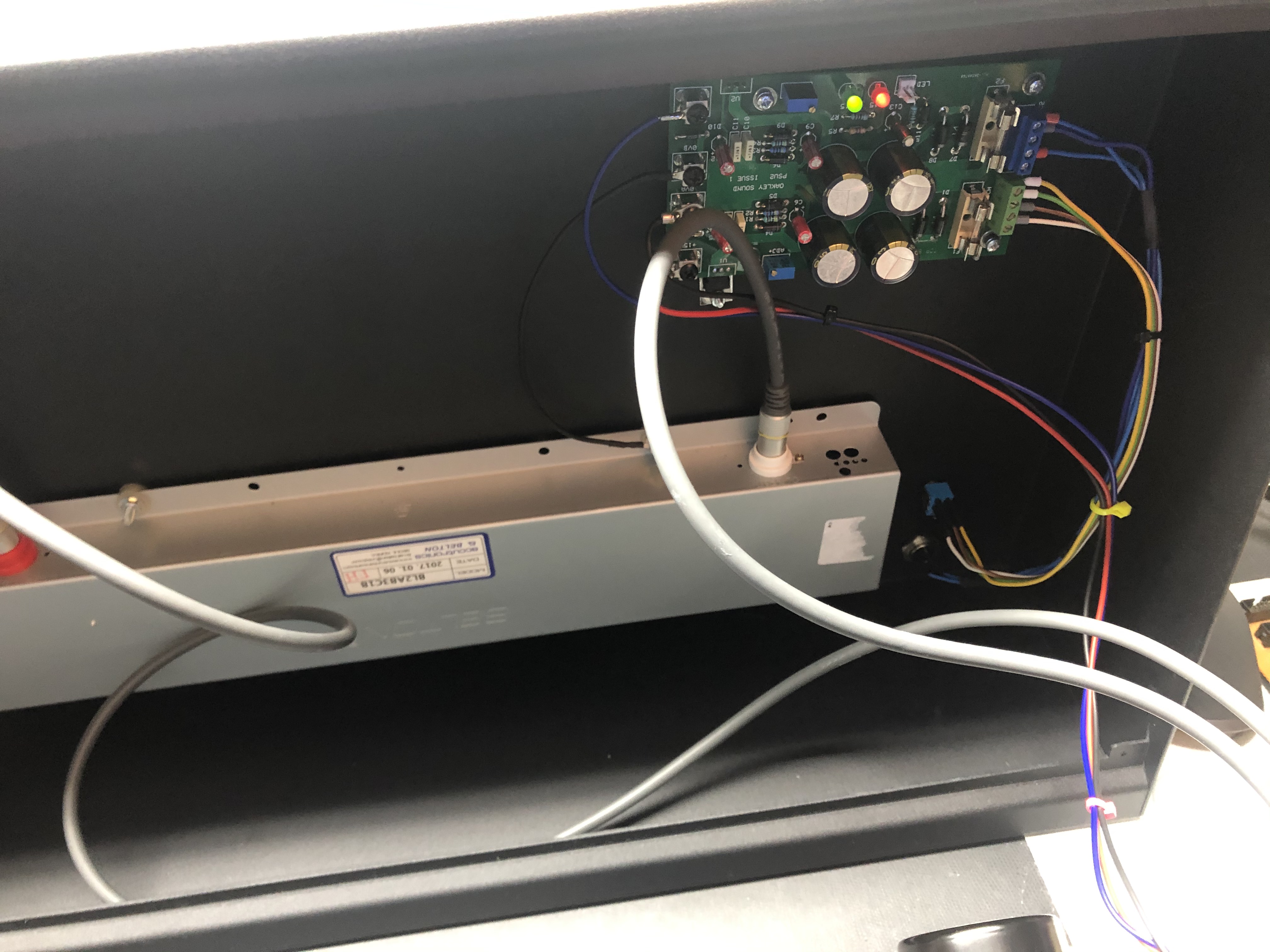
Example for TTSH installation:
the case of the TTSH is used as a cooling block
Heres´an example of an isolated Installation with Glimmer and plastic rings - its important that both voltage regulators are isolated - there's also a plastic inlet on bottom of the nut which isolated the screw from the voltage regulator body.