...
| ID | MatthiasIssueNr. | Issue release date | Issue | Solution | ||||||
|---|---|---|---|---|---|---|---|---|---|---|
| 1 | 29 | 19.dec.2019 | When mounting the matrix to the lower frontpanel by the ground terminals, a distance of 1 - 1.5 mm can be noticed between the matrix's surface and the frontpanel. | File down the narrow part of the bushing to at least 3 mm or less. Plan B: try a washer or 2 of them (not tested yet) Plan C: Re-drill the matrix at these two holes to the diameter of 8 mm and file down the tooth. 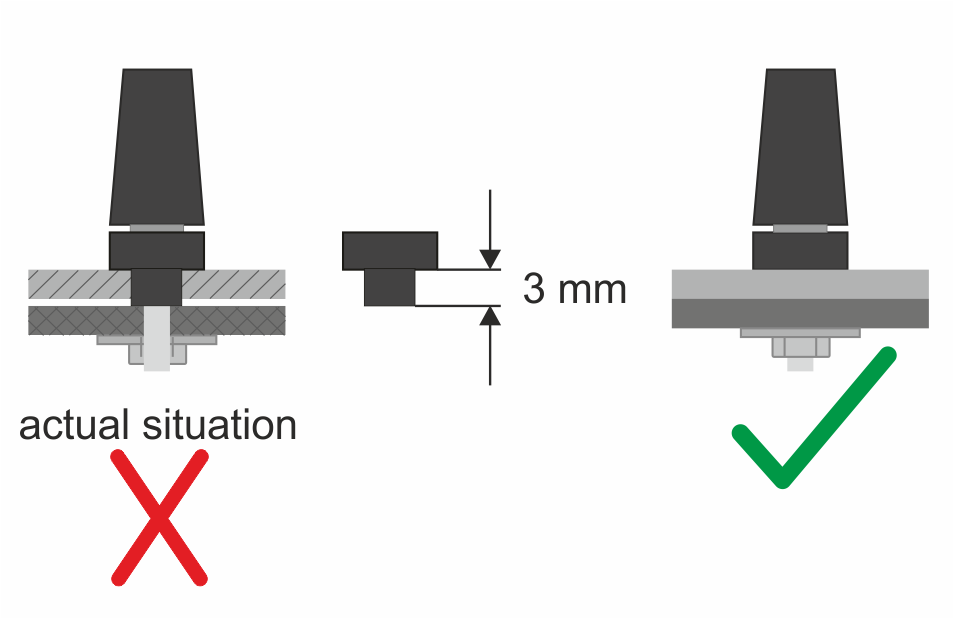 | ||||||
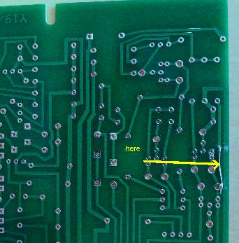
| 2 | 28 | 16.dec.2019 | At the Z board there is a link missing on the 12 V trace. The failure affects OSC 1.. |
| ||||||
| 3 | 27 | 16.dec2019 | At the Z board the captions of the presets are not printed. | See herefor the attached page of the population guide.
| ||||||
| 4 | 26 | 08.dec2019 | "I meanwhile realized the EK construction manual gives no detailled information about mounting the matrix to the lower panel. So I decided to extend the manual by an additional page. Find this new page attached to this Newsletter. With this change, the actual EK construction manual now is rev. 1.24 and will be part of the next shipments (serial 078, 101, 106)." |
| ||||||
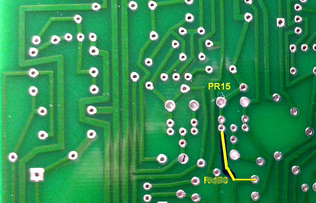
| 5 | 25 | 04.dec.2019 | PCB Version: Y19/09/mk4 cba There is no trace error at the X board. It is at the Y board - I am sorry. As reported, it was already soldered by Derek before packing the Electronics-Kit. | Therefor see the attached photo. If this link is not present, solder a piece of wire to complete the trace.
| ||||||
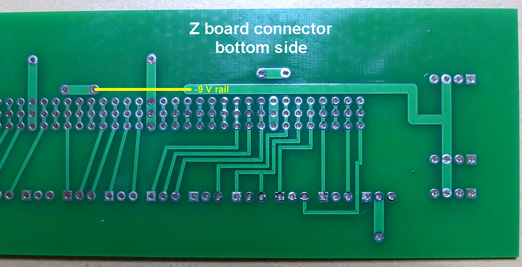
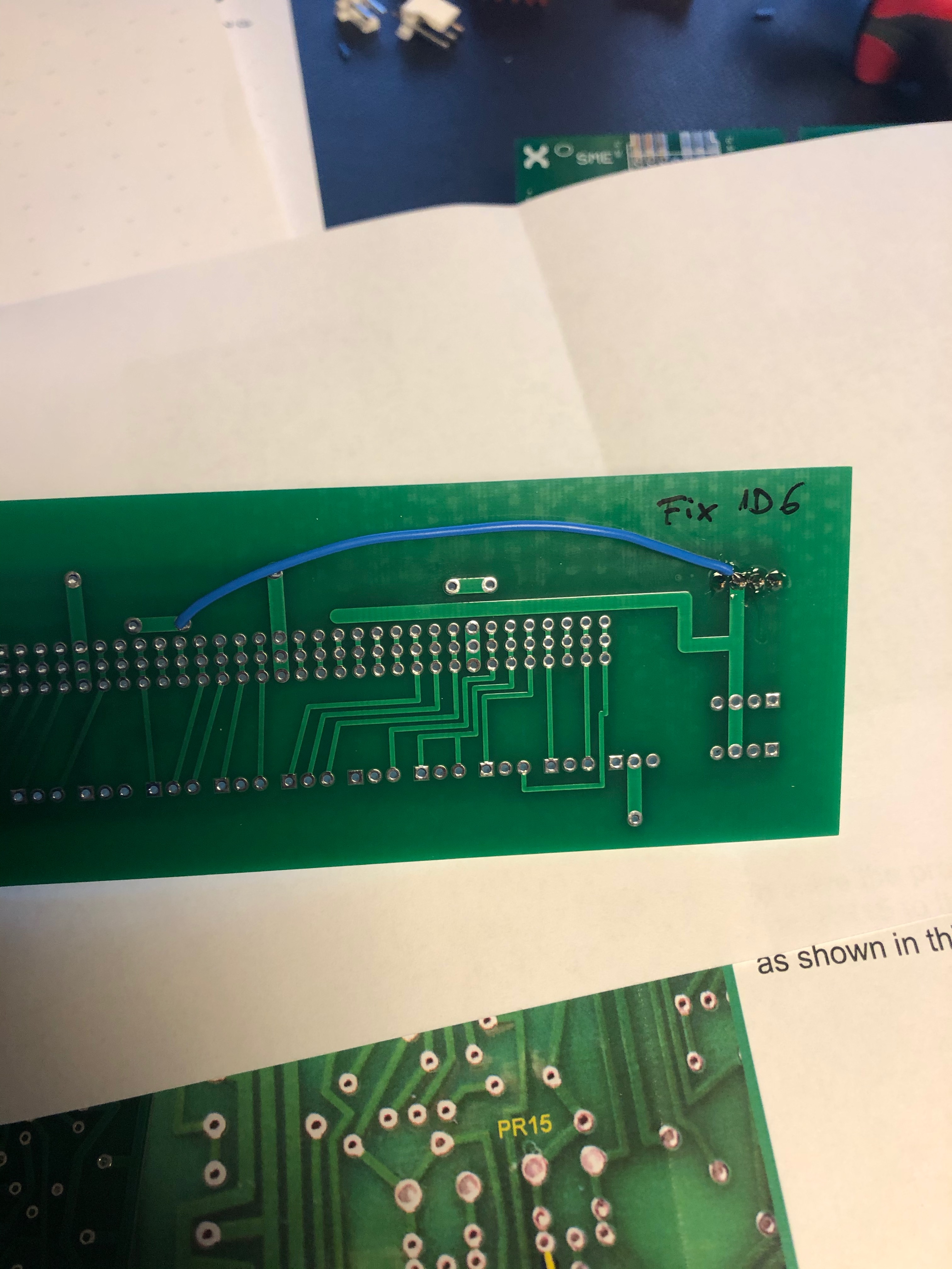
| 6 | 24 | 03.dec.2019 | There is a track error at the -9 V rail. See the attached backplane photo. | Solution: Solder a cable as shown in the picture (yellow link) to connect the right part of the -9 V rail.
| ||||||
| 7 | 22 | 03.dec 2019 | Info only: Please refer to page 2 of the Population-Guide Version 1.92 | |||||||
| 8 | -- | 23.dec 2019 | Info: the 1K 2Watt resistor for the X board is for the PSU wiring... not on the X board pcb use 1% metal film resistors or select the 2% resistors on board X. | |||||||
| 9 | Issue 30 | 27.dec 2019 | R 12 (PSU / earth link) The wiring diagrams were not correct since an update earlier. This causes a parasitic voltage and in some cases obviously a strange behaviour | Solution: So the next shipments will include construction manual rev. 1.26 or even a higher revision. File: | ||||||
| 10 | -- | 29.dec 2019 | howto for X card remove the Pin 4 and 8 (the connector for the 2 TIp3055) |
| ||||||
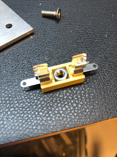
11 | Patrick | Early 2020 | use a 7mm drill that the flat screws fits flat on bottom of the PSU base plate, only as seen on the picture on right side. wide also the fuse holders with a 4mm drill that the delivered screws from the kit will fit thru the fuse holders. |
| ||||||
| 12 | 31 | Early 2020 | Major Problem: | Solution:
| ||||||
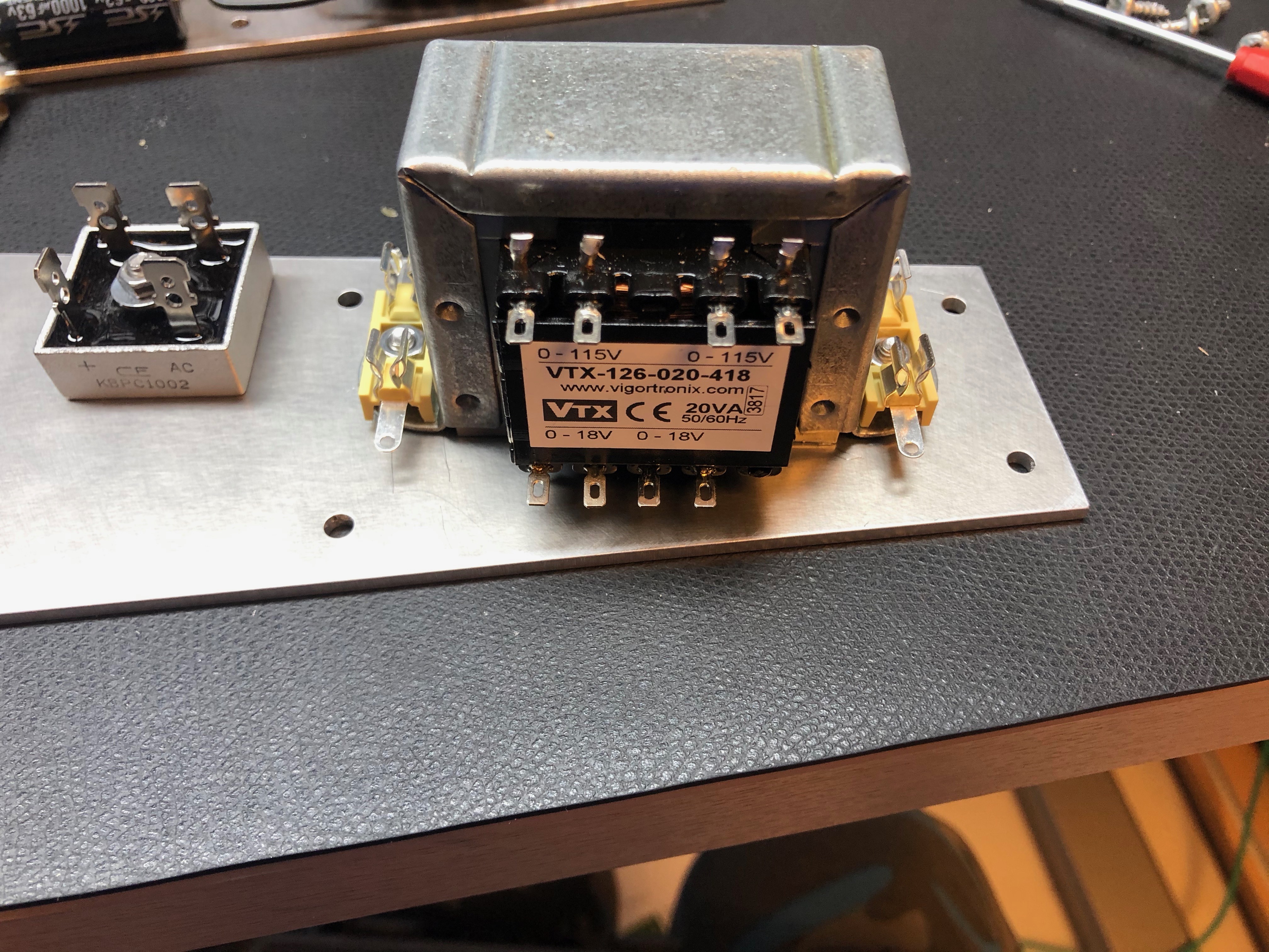
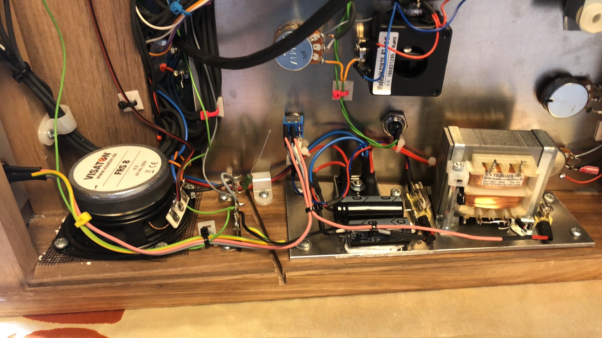
| 13 | Patrick Issue | Summer 2020 | Problem: the regulators are too hot for my experience - we waste too much energy in heat | the 18V AC transformer is "wrong" here - we have a 27V DC output after the bridge rectifier, beer we only need 15V DC. so I tried a 12V AC transformer which gives you a stable 18V DC output under load which is much better, the heatsinks are only at 22-30 degrees instead of 50C or higher. TME PART number: TS20/023 please note: you have to drill 3 holes in the PSU back plate to mount this. | ||||||
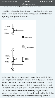
| 14 | Patricks | Summer 2020 | Problem: Envelope bleeds in VCOs | the Lamp is the root cause. it can be replaced by a LED (preferred yellow) you also Need a 6V8 zener (6.8V zener Diode and cable tube/shrink) it was tested by me and works fine. TME Led holder with included LED: 2658.8073 (mentor vendor part nr.) 6v8 zener diode: BZX55C6V8-TAP
| ||||||
| 15 | Patrick | 07/2020 | improvement: Buffer see bottom picture Paps offer buffer pcbs.. which means there's no voltage drop for the CV or Audio signal when you patch multiple sources and destinations ( 2x joystick to all VCOs Freq. for example) see above pictures. | http://www.portabellabz.be/synthipcbs.html Install. guide: | ||||||
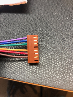
| 16 | Patrick | 11/2020 | general info about the wiring | 100meter (roll) BKL Electronic 1509008 available by voelkner and conrad.de few meters are supplied with the cloney kit, but it was´nt enough on my builds. | ||||||
| 17 | Patrick | 11/2020 | Powersupply Powersupply change
click to enlarge
| I removed the Internal Powersupply - transformer to have less hum and EMV in the reverb and circuit. And we don't want Main Power handling for people who don't have the knowledge - its forbidden in some country to "play" with Main power. My solution is to use an external Yamaha PA-30 PSU (available in 110V and 230V). the wiring must change too. Things you have to change:
2. Install the above Panel in place of the IEC socket and install there a CLIFF FC684203 3. install a DPST switch (the original Lower Panel Powerswitch is a SPST) 4. connect PIN 1 and 3 of the Cliff connector to the DPST Switch, the switched outputs goes to the Fuseholder 5. Pin2 of the Cliff jack is the Ground, which has to be connected to the CN groundbus. 6. we don't need anymore the 1K resistor at the bottom Rail, we use just one STAR ground connection. | ||||||
| 18 | Patrick | 11/2020 | Matrix Change
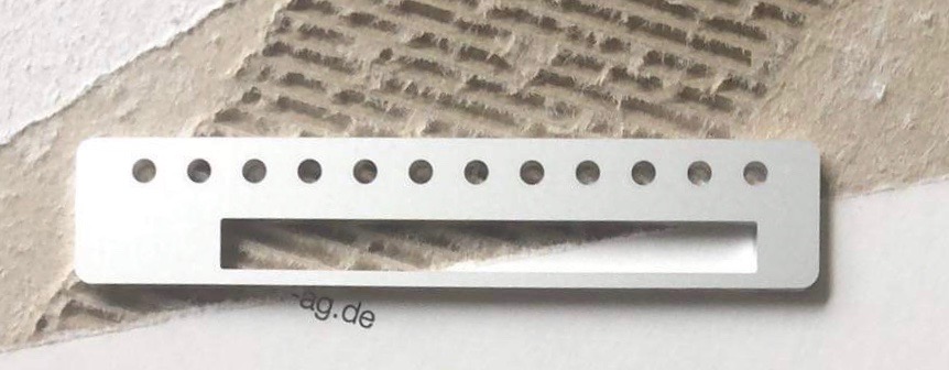
| I have an Ghielmetti Matrix installed, with some modifications you can install an Edge Connector for Prestopatch cards. Here's the Frontpanel Designer file for the Pinpark cutout, feel free to change it. change in the panel the thickness to 3mm !!! File: | ||||||
| 19 | Patrick | 11/2020 |
| you can order this from Ponokko or Formular for 42Euro 3mm clear Acryl Glas | ||||||
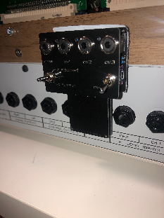
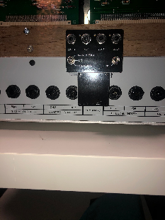
| 20 | Patrick | 11/2020 | CV- GATE Interface the Connectors on left and right side to the Interface are still usable
| http://www.portabellabz.be/cvgate.html Manual: BOM: some Parts from Reichelt (I don't have a full list) Trimmer: 64W-100K Diode: BZX 55C5V1 VIS (5.1 zener) 4x 3.5mm socket CLIFF FC681374V 2x NK236 Slideswitch 2x LM741CN 1x MKS2-50 680N. (680nf cap) | Buffer for Matrix | Paps offer buffer pcbs.. which means there's no voltage drop for the CV or Audio signal when you patch multiple sources and destinations ( 2x joystick to all VCOs Freq. for example) see above pictures. |


Calibration (the better Version)
...