TTSH rev.1 Release
BOM
TTSH Rev.1 known Issues
TTSH Rev.1 Hardcore builders guide
STATUS finished
Released 11/2013
the buildguide is only for rev.1 - check for TTSH rev.2 this PAGE rev3 here
last Modification Date: 20.June 2017 - Voltage processor TL071 instead of LM301
BOM from me: BOM TTSH modified rev.1
Dokumentation: http://thehumancomparator.net/building/
Schematic: TTSH-schematics.pdf (also avaiable on zthees webserver)
PCB reference designators: TTSHcompplc.zip thx to http://tauntek.com/TTSH.htm
Muffwiggler Forum infos: (first page) http://www.muffwiggler.com/forum/viewtopic.php?t=98954&postdays=0&postorder=desc&start=2130
ATTENTION
wiring from PSU to the module headers are wrong "silkreen error" +/- must crossed - doublecheck before power up modules,
you find other issues in the second tab here
Please read Buildings tips and known Issues site to save time and money.
I have completed few TTSHs and can share my experiences here.
Dont solder switches, Pushbutton, faders and jacks prior finally assembly - the orientation is only correct by placing all jacks/faders together with the Frontpanel because the pcb bends a bit.
Result from Widy/DSL-man:
BOM failure - following parts arent listed
----------------------------------------
1x BC558b S&H missing ( need 9 .. BOM say 8)
1x 150K S&H missing ( not in building doc)
1x100p (missing part )
1x 150K S&H missing ( not in building doc)
1x100p (missing part )
bc337 for noise fix
parts left DSL-man/widy
------------------
1x 47K
2x 100N
optional parts from power input (hum modification)
optional parts from VCO bleed fix (caps)
BOM page own:
this modified BOM is for TTSH rev.1 (sale from December 2013)
Here is the Original BOM from the great TTSH (Arp2600 clone)
Mouser cart
https://de.mouser.com/ProjectManager/ProjectDetail.aspx?AccessID=4998691276
please add:
- 1x Powerswitch 633-CWT12AAS1
- 1x BC558 (in sum 9 )
some missing parts like Transistors, ICs, Reverb Spring, PSU, connectors, jacks and many more:
- Spring reverbs are avaiable from Banzai
- PJ301BM Jacks are avaiable from thonk.co.uk or http://erthenvar.com/store
- Screws are avaiable from me

- for speakers you can use Visaton FC8 /FS8 or similar
Tip
check the pcb for failures !
you have to mark the pcb with labels or sticker by using Mods/bugfixes. otherwise you have to desolder parts.
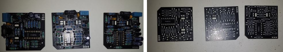
Starts soldering the VCO Boards:
Online building documentation failure:
for VCO pcbs in zthees building website shows 1x61k9 but needed on each pcb 2x 61k9 resistors
http://thehumancomparator.net/4027-2/
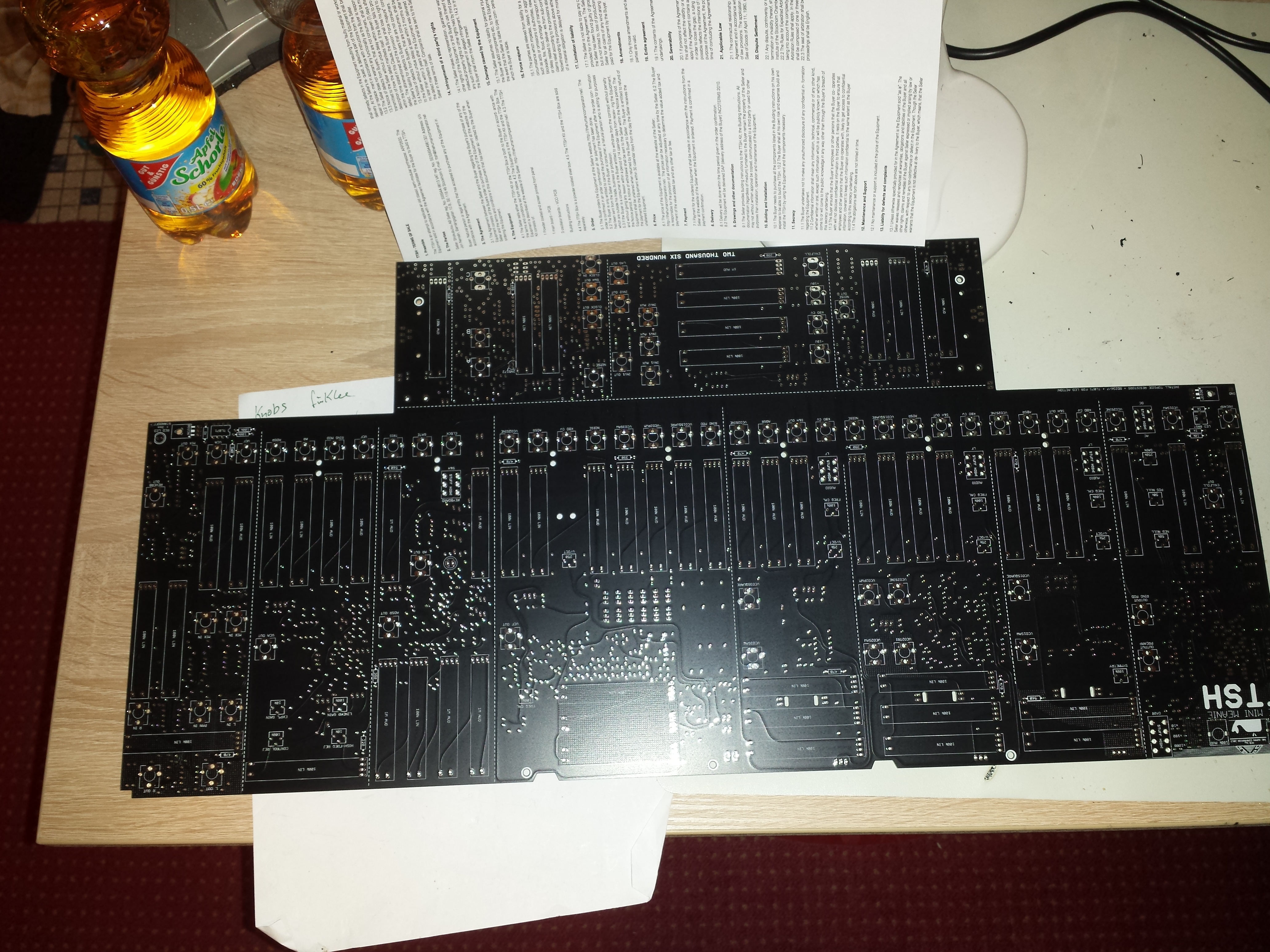
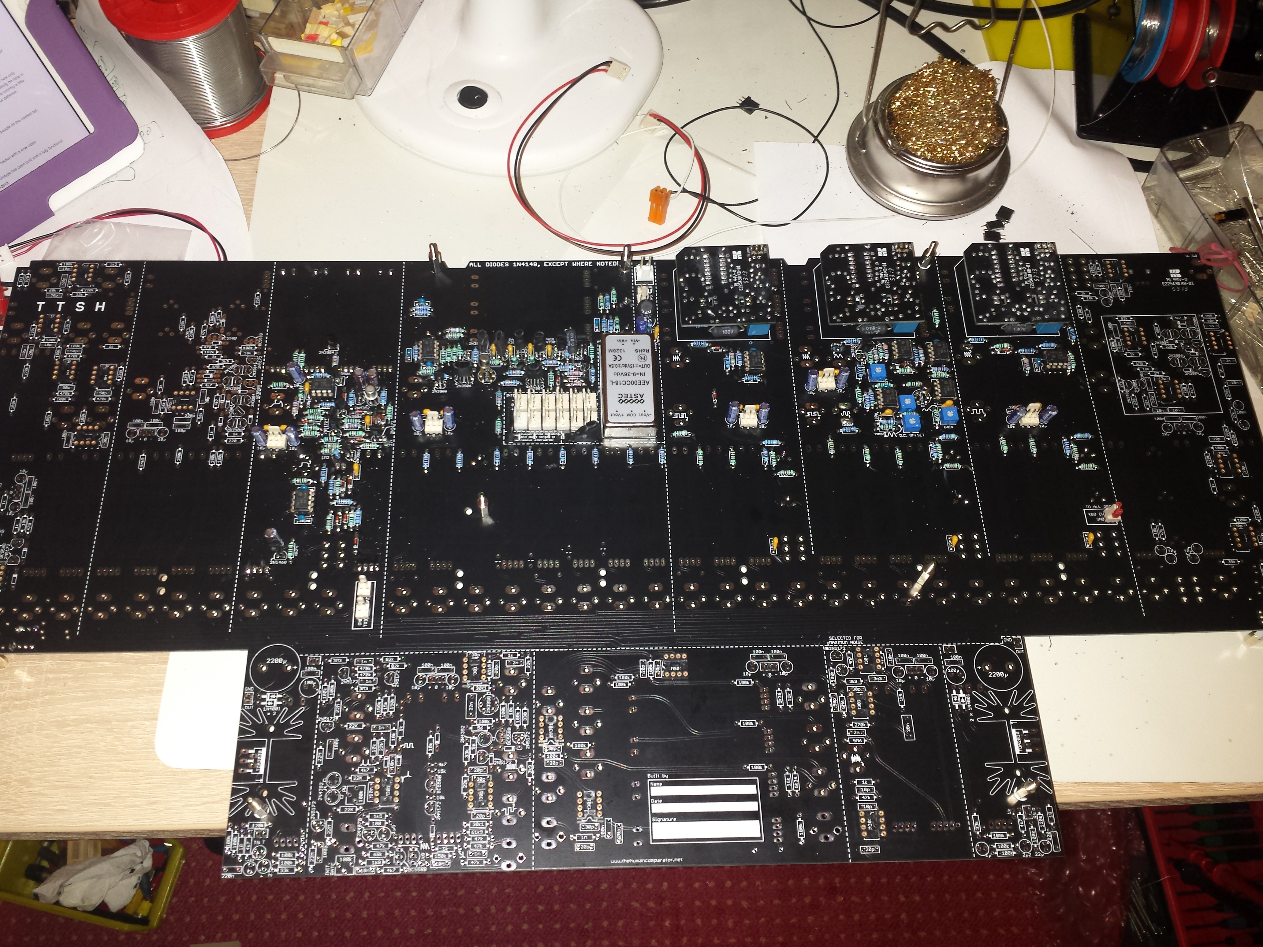
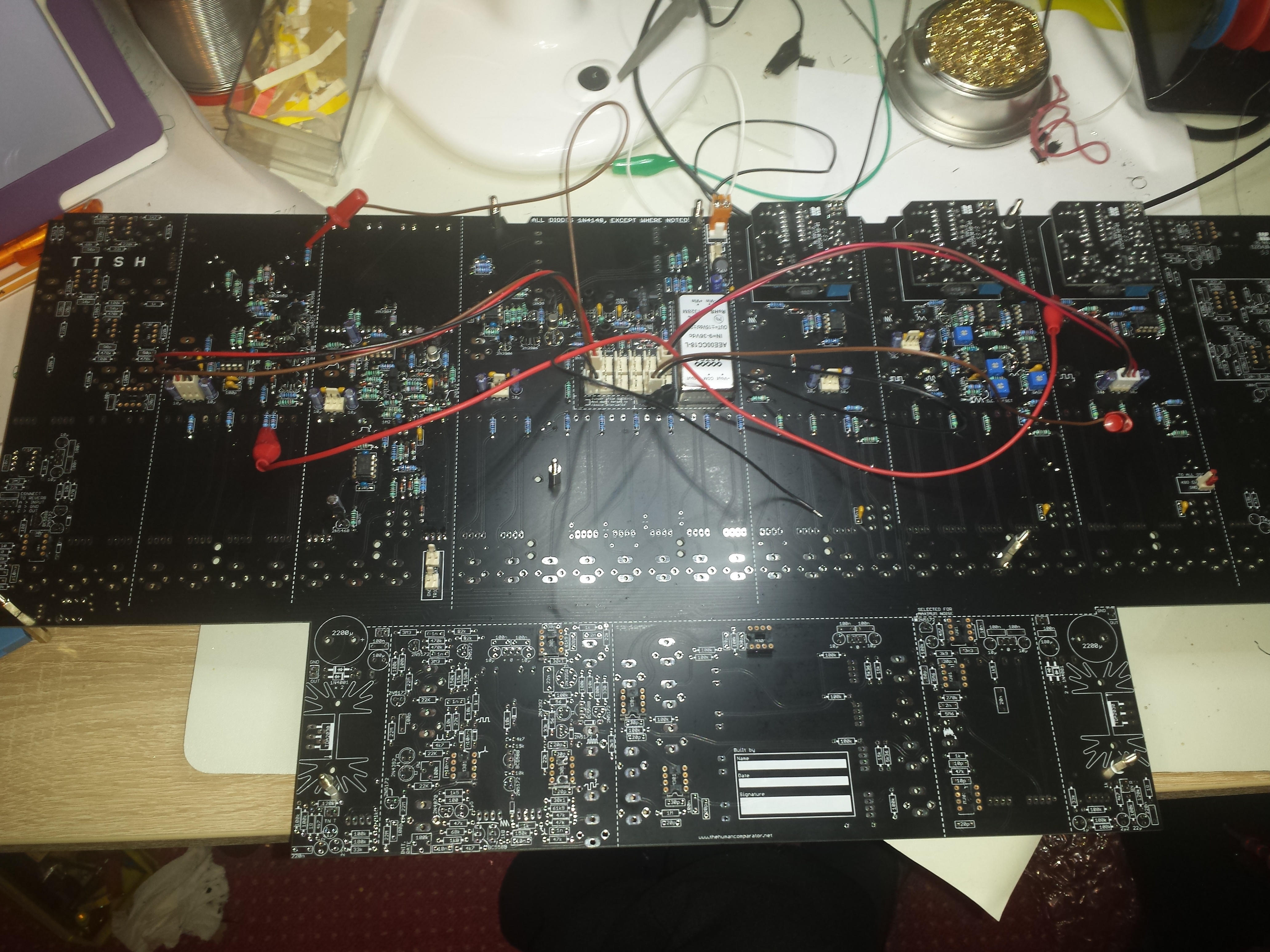
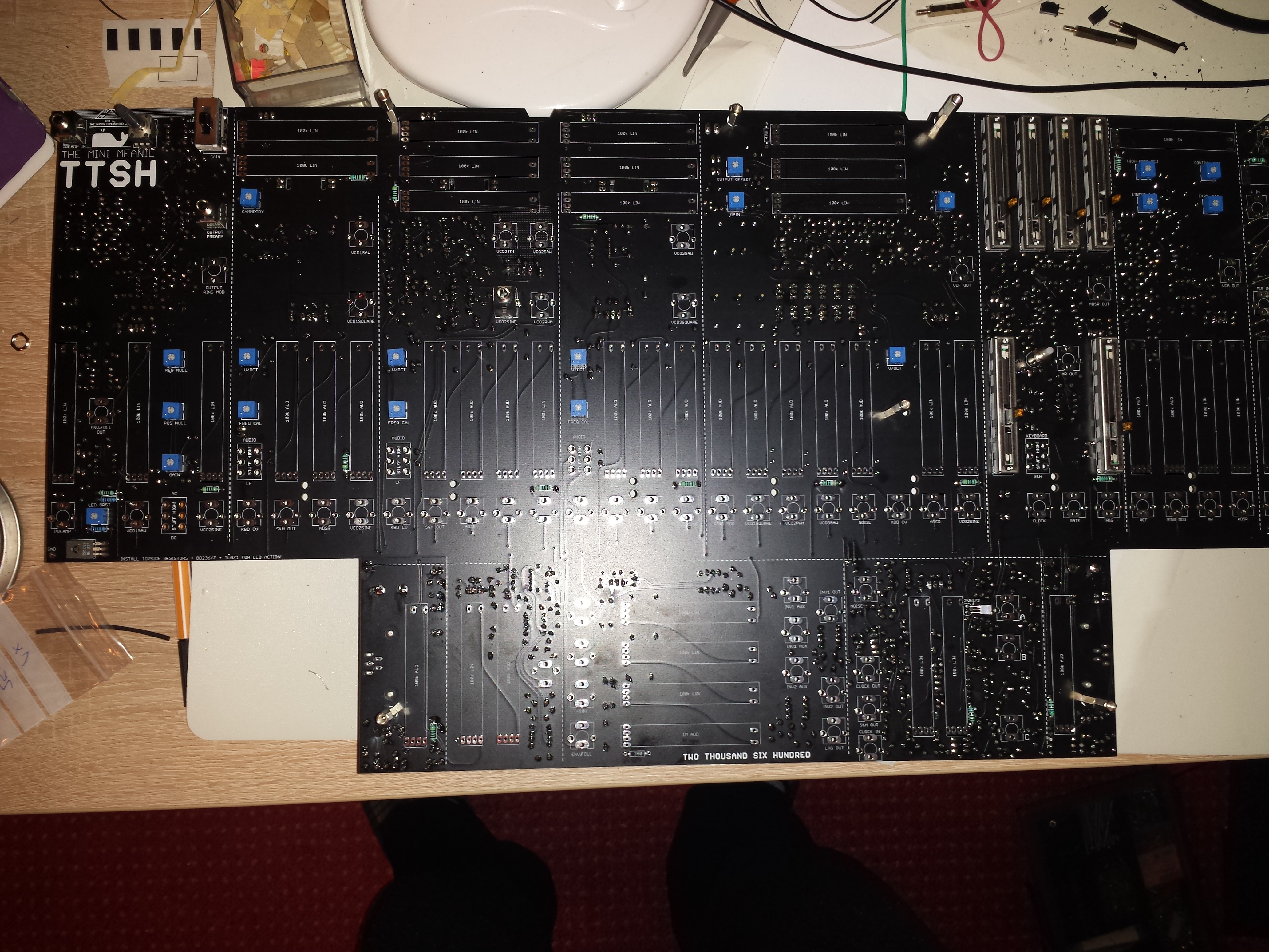
Start assembly Main PCB
Use standoffs/Spacers:
![]()
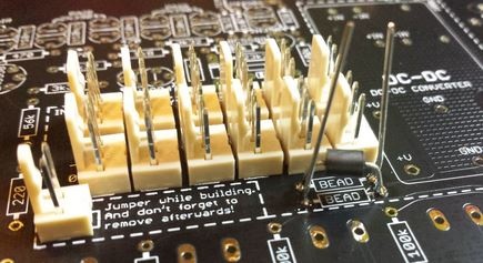
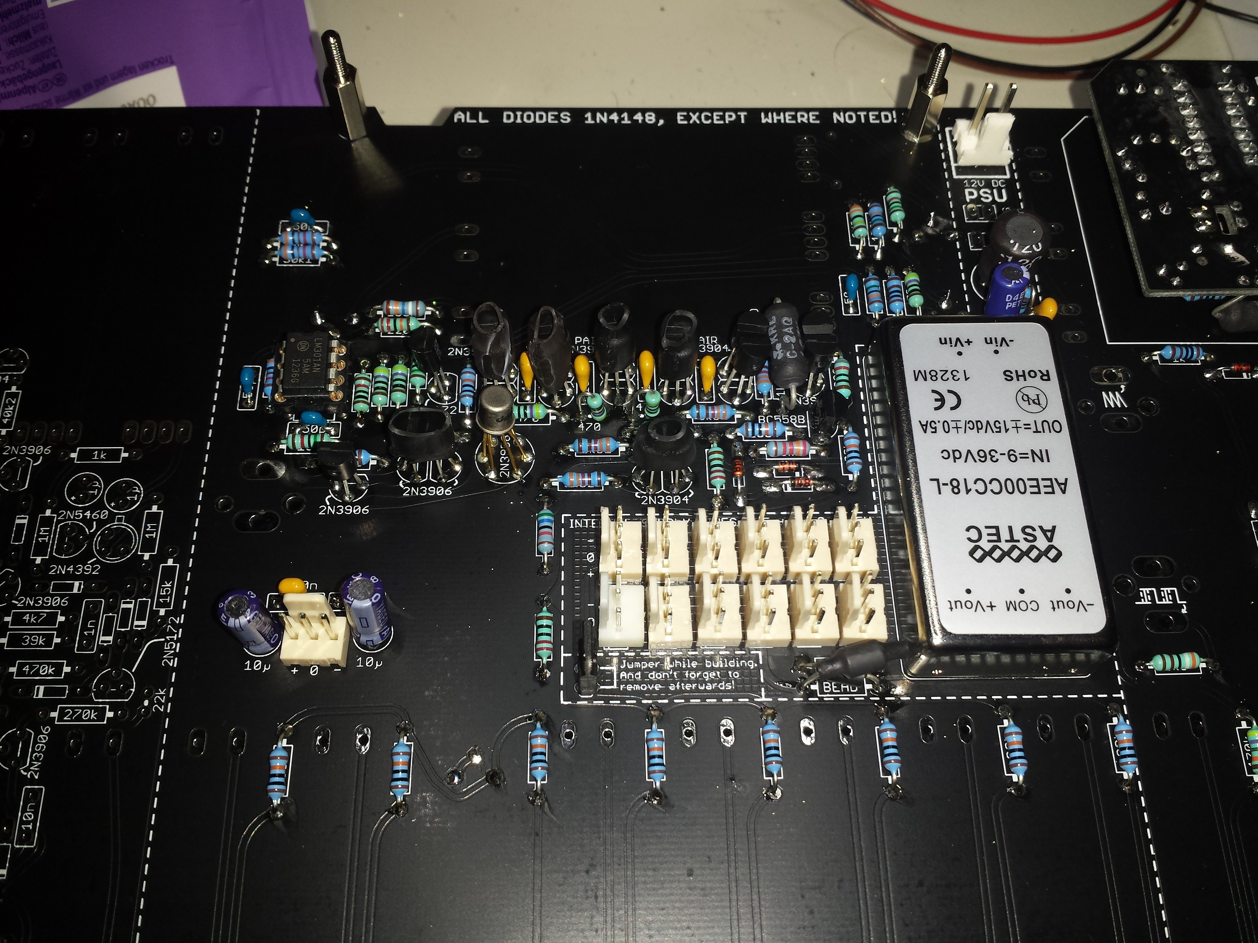
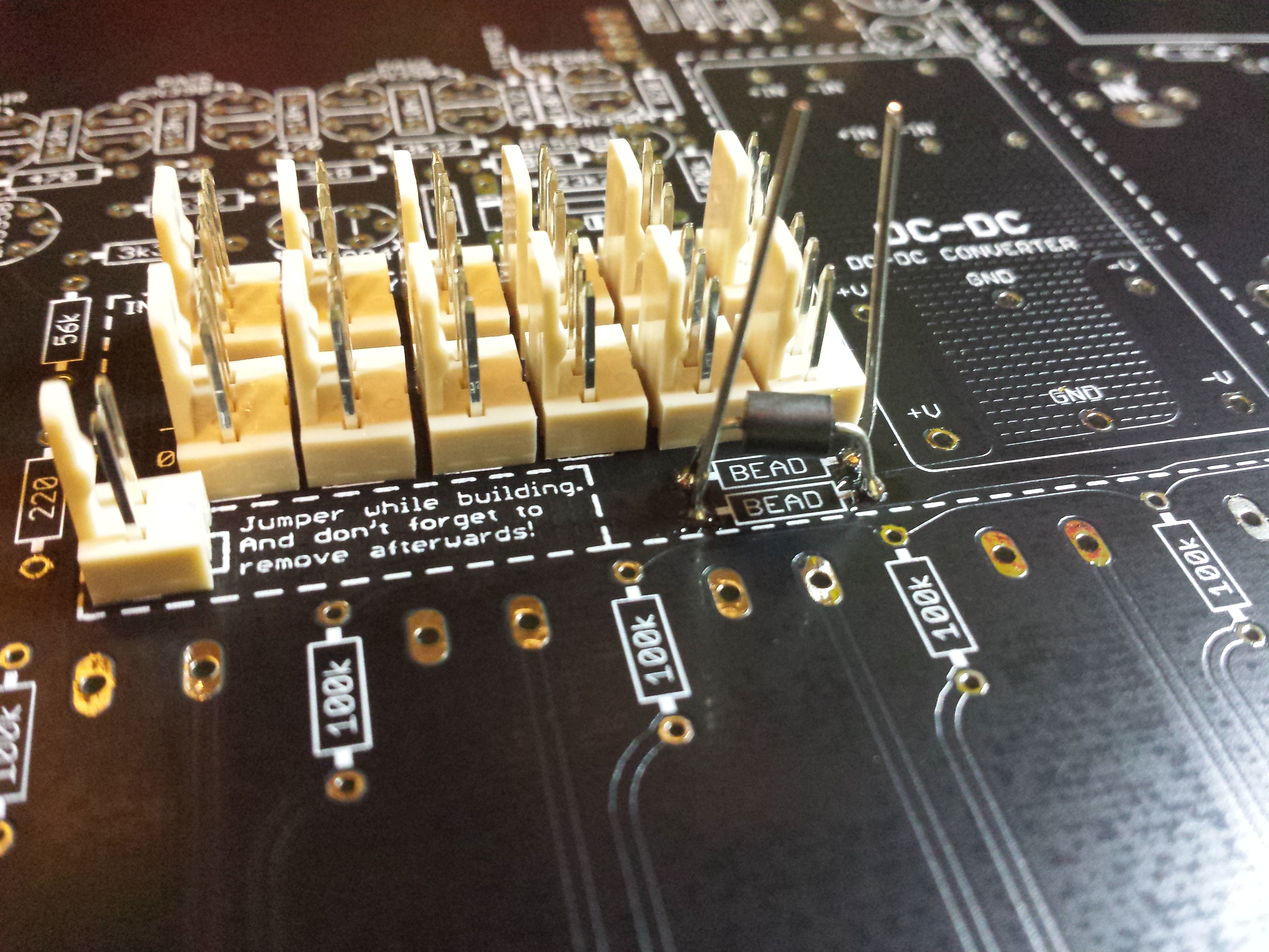
Add the Jumper close to the power section (left hand of ferrit beads)
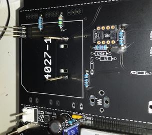
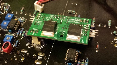
Mounting VCO-1 pcb with long headers, but solder before 150K & 3m3
please read at first the known issue page - VCO2/VCO3 issue
( i use long headers instead of zthees preferred headers to have more space between subvco parts and mainpcb, zthees solution is better for troubleshooting, but you have to unmount the frontpanel due to cutting the cabletie)
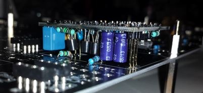
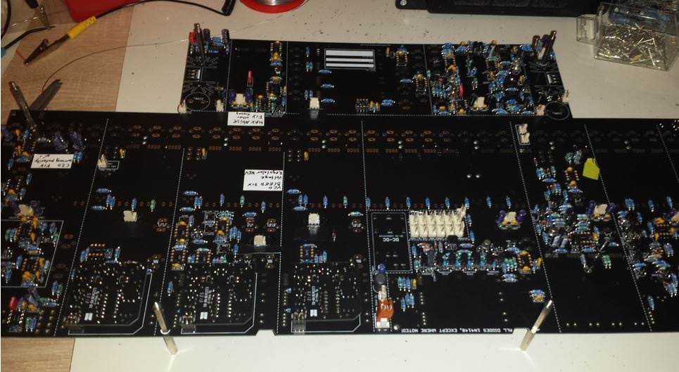
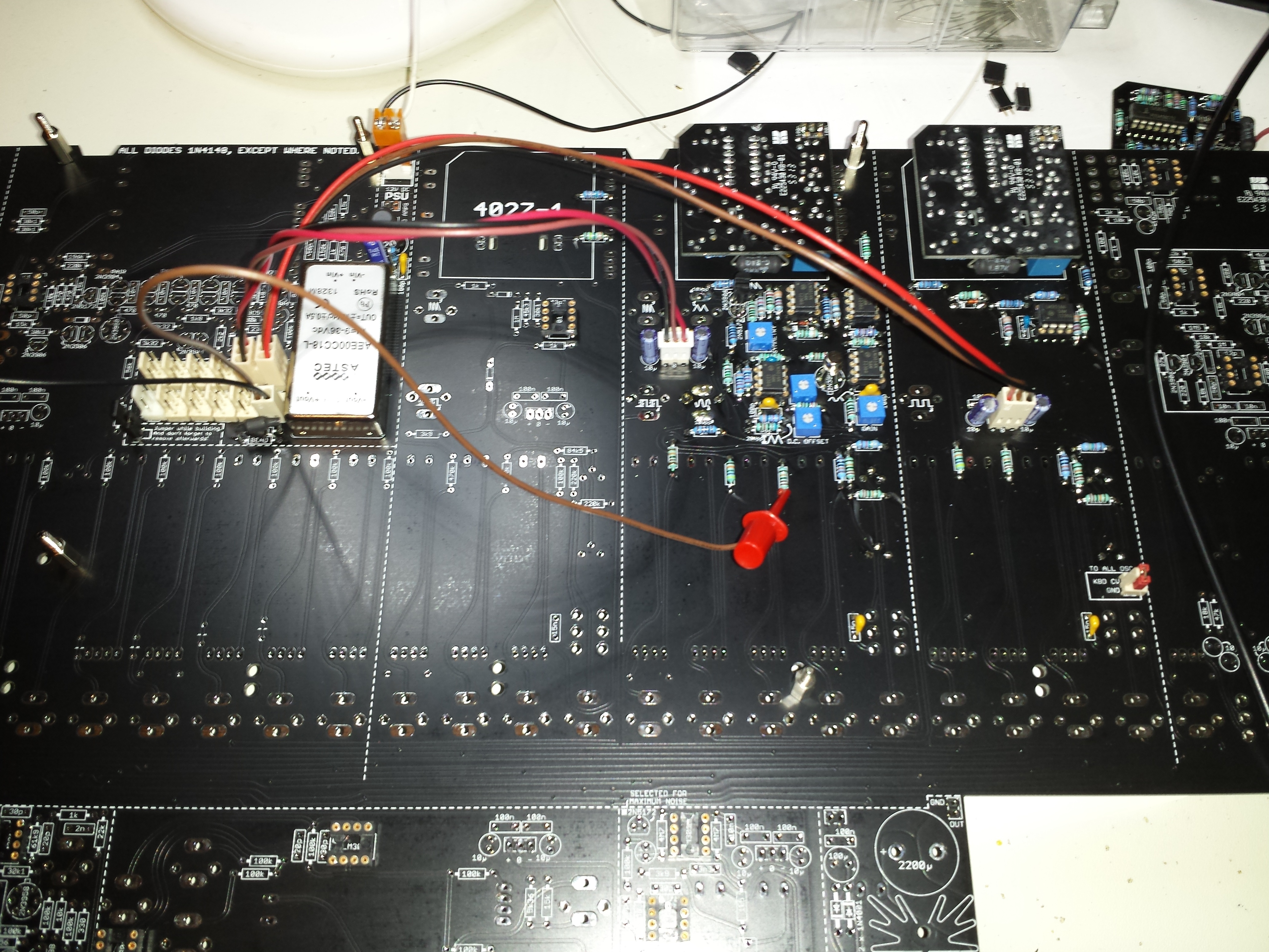
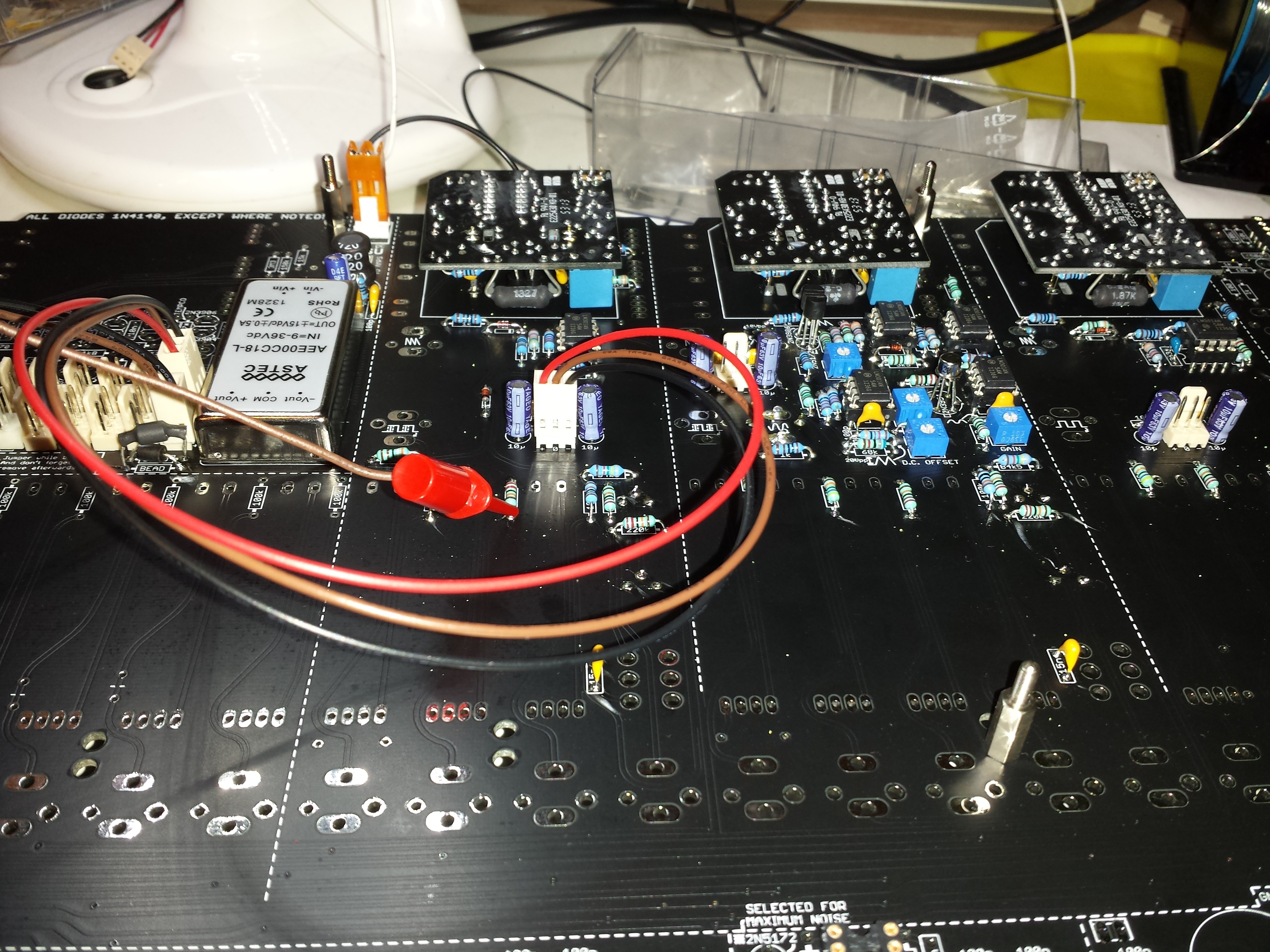
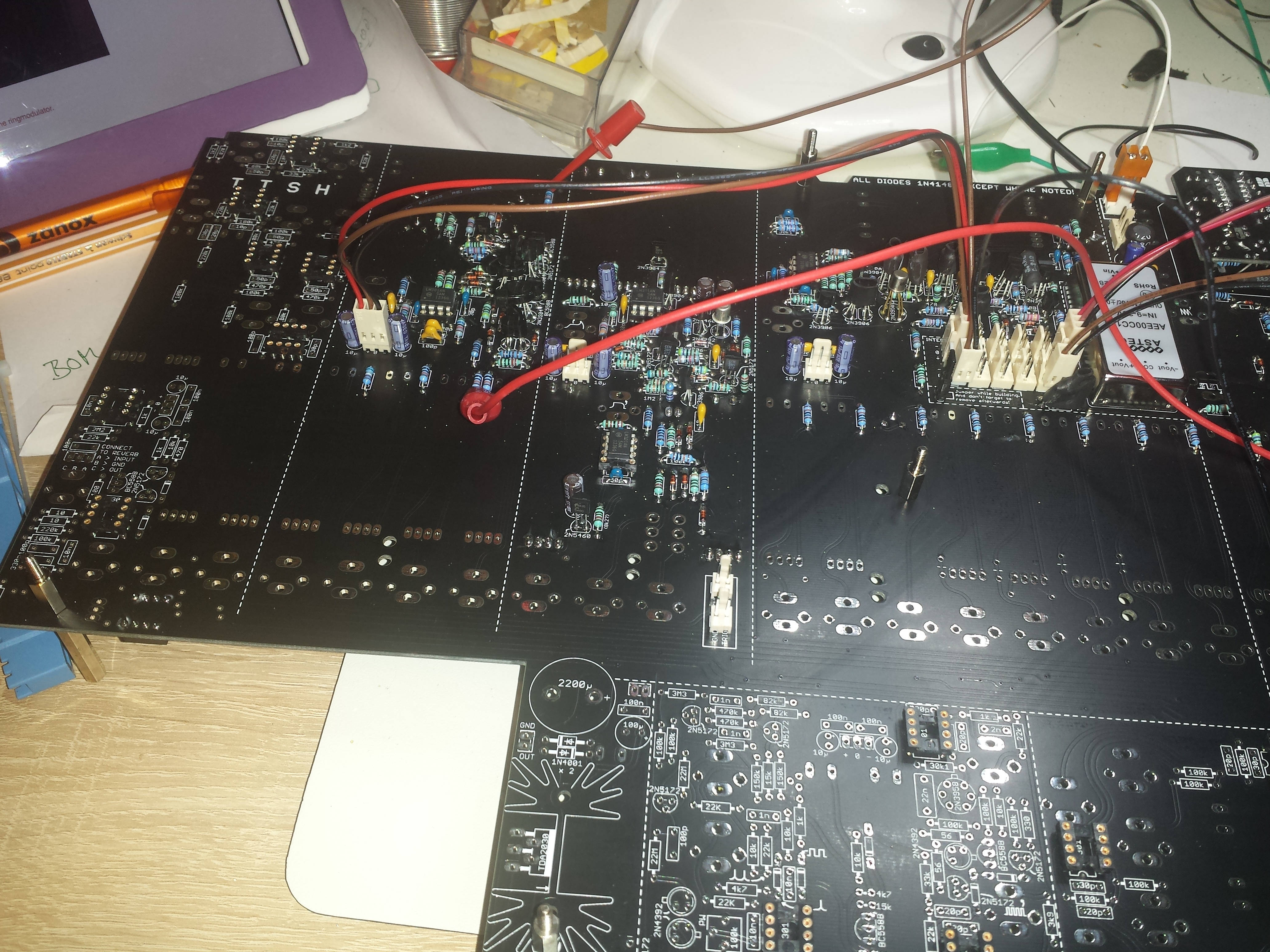
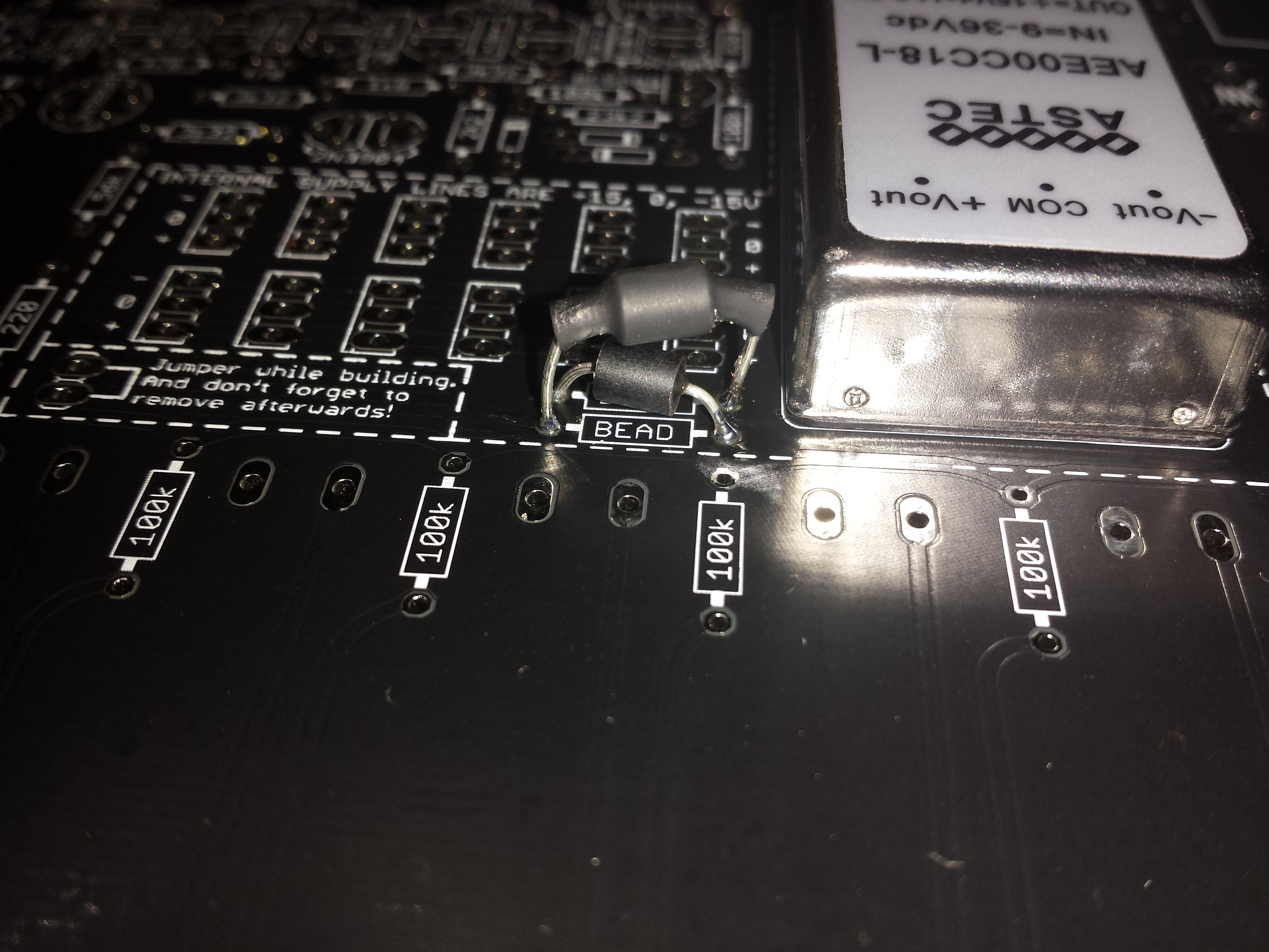
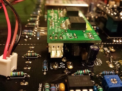
PSU with DC-DC Voltage "regulator"
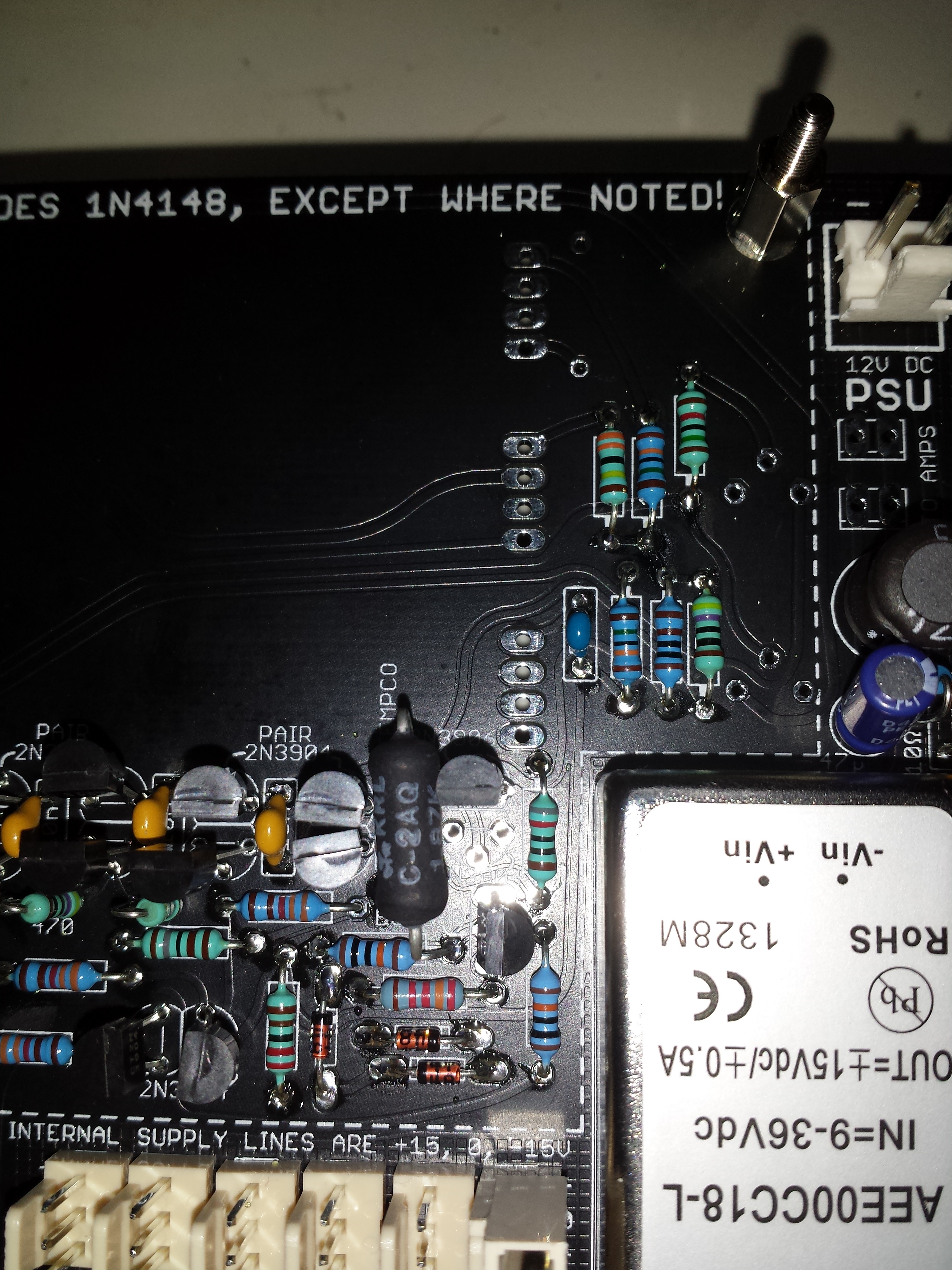
right picture shows the X-crossed ferrite bead to fix the -15/+15V silkscreen error,
cross one Ferrite on top pcb side - the ferrite on other pcb site (not shown here)
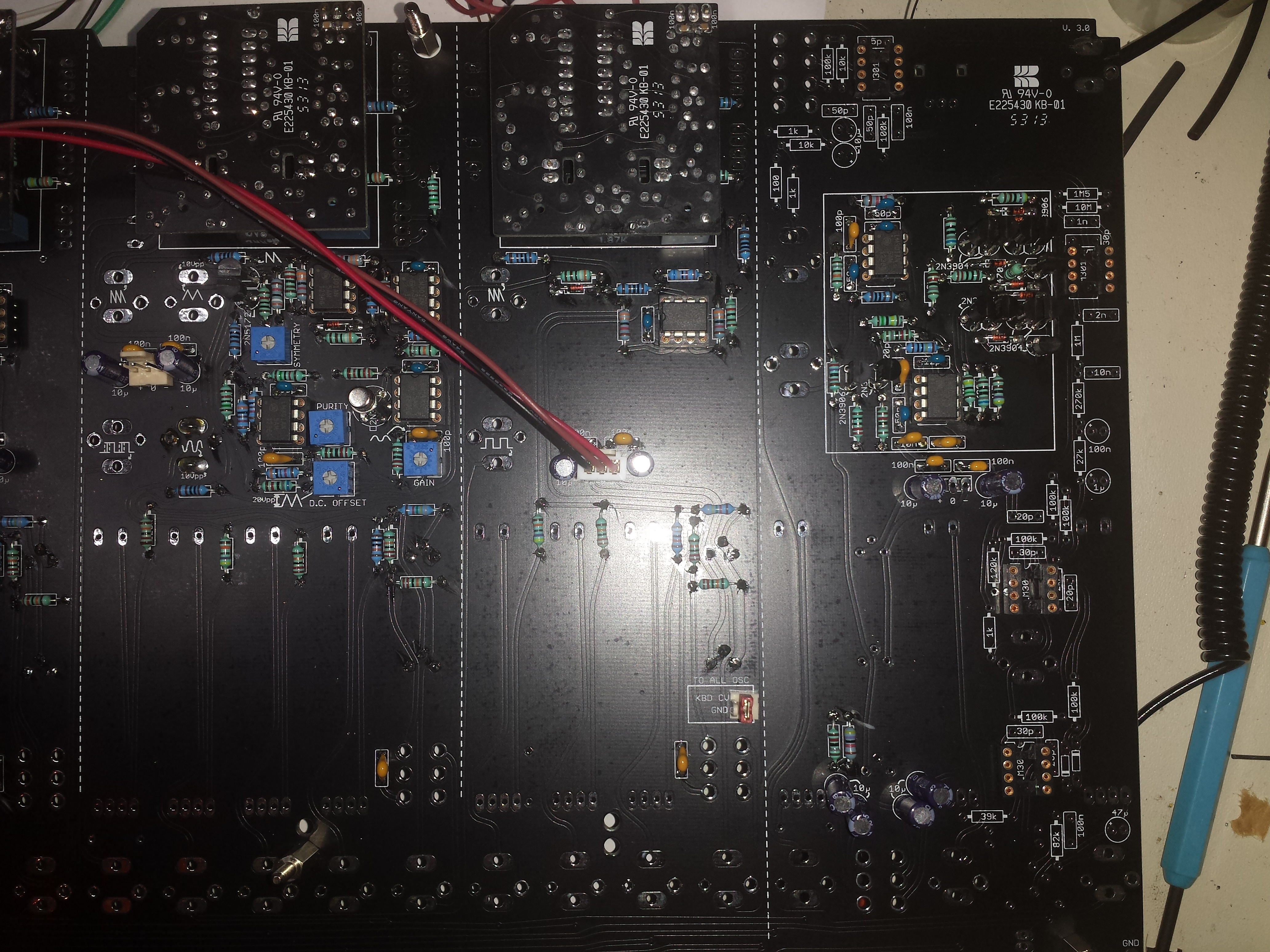
VCO testing - wiring a +15v cable to resistor and probe ..
further: dont solder the needed jack complete - solder only a bit, because the frontpanel don´t fit with this position 100%
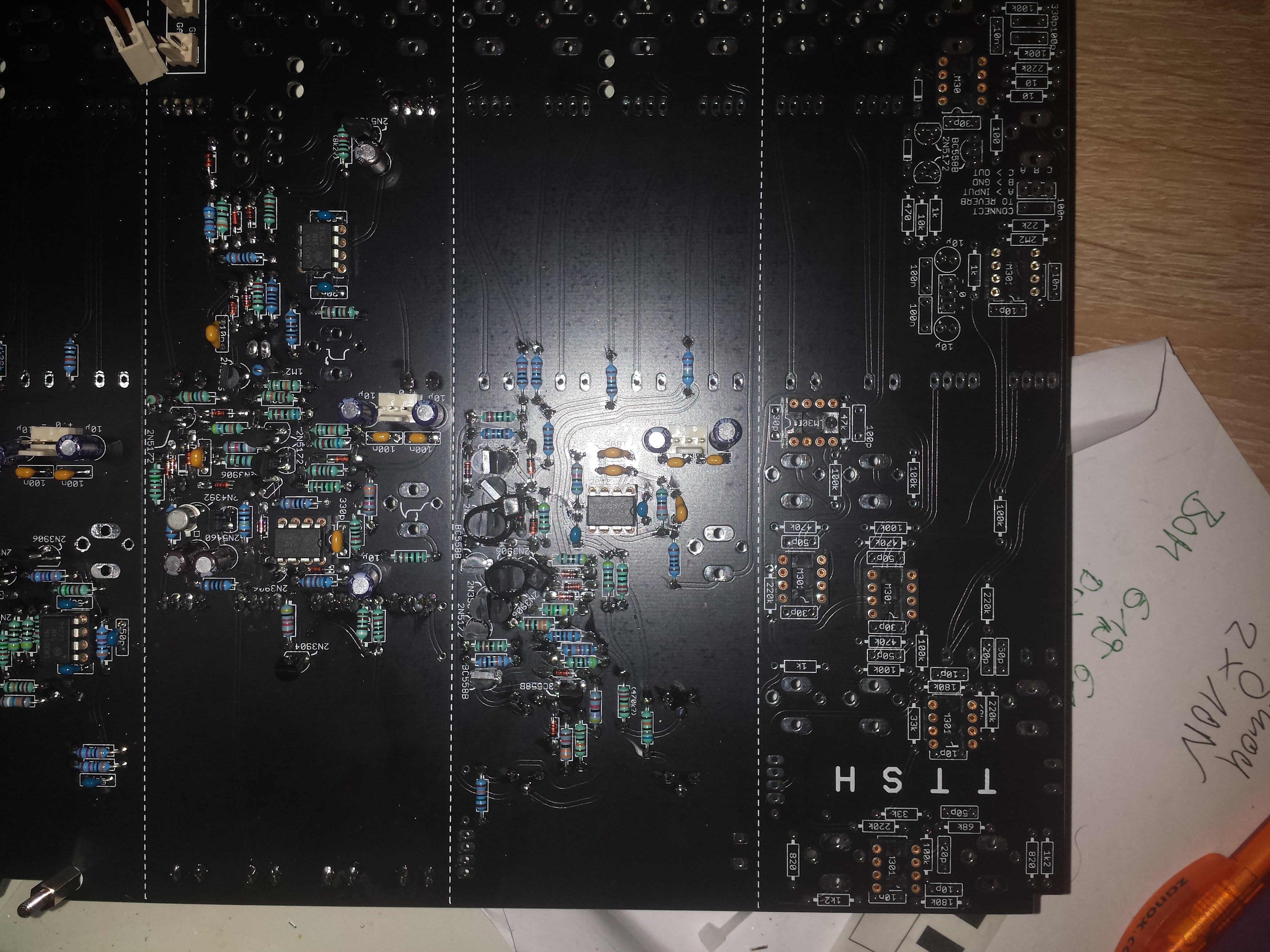
VCF picture - handle with care - 2n3904/06 - BC558 doublecheck the position near Tempco
further please read careful Jons building guide for VCF - there is a issue with matched pair 2N3906 - silkscreen error etc - check here
AR/ADSR
VCA
for testing: test with probe a VCO (need +15V cable see VCO testing above)
feed the VCO signal to the VCA and check the waveform with a oscilloscope.

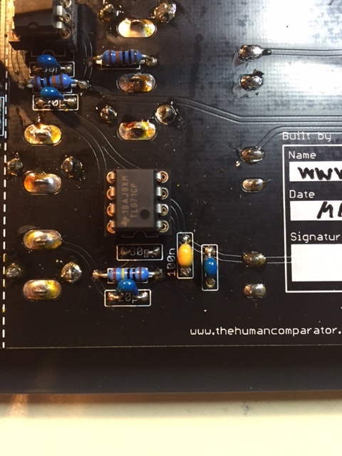
Ringmod, Preamp, Envelope Follower
Mixer
Don´t solder the pot, switch, jacks - the frontpanel dont match with the Partposition yet.
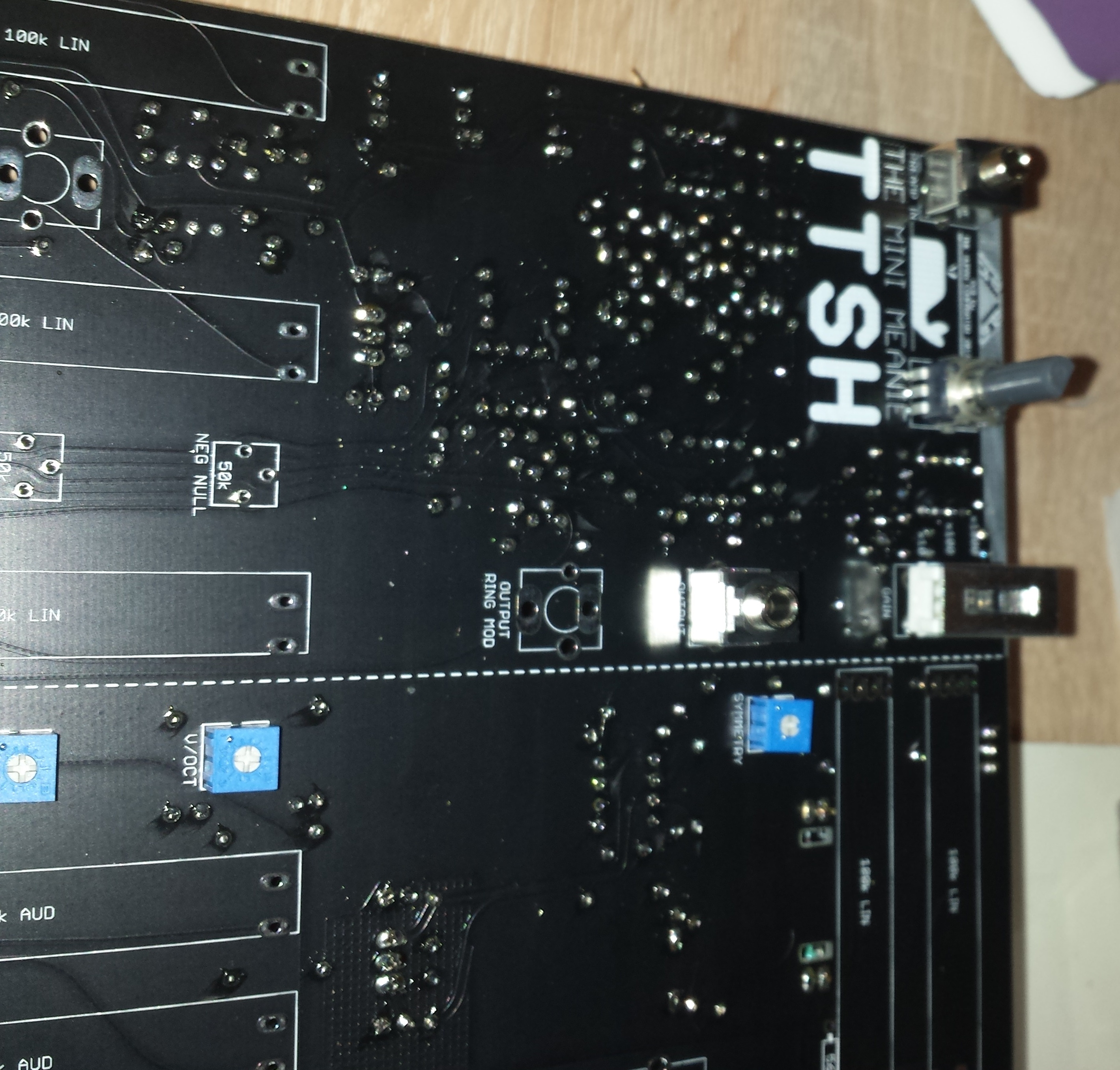
Noise, Voltage Processor
Warning
with the 2n5172 the noise is distorted and have a very high gain..
tested Rolution:
leave out the 2n5172 - use a bc337/16, - bend right leg to top, solder a 10K resistor in series to the 1uF cap.


Change in the voltage processor section the LM301 for a TL071 and dont assemble the 30pf capacitor. (its only one IC to be changed)
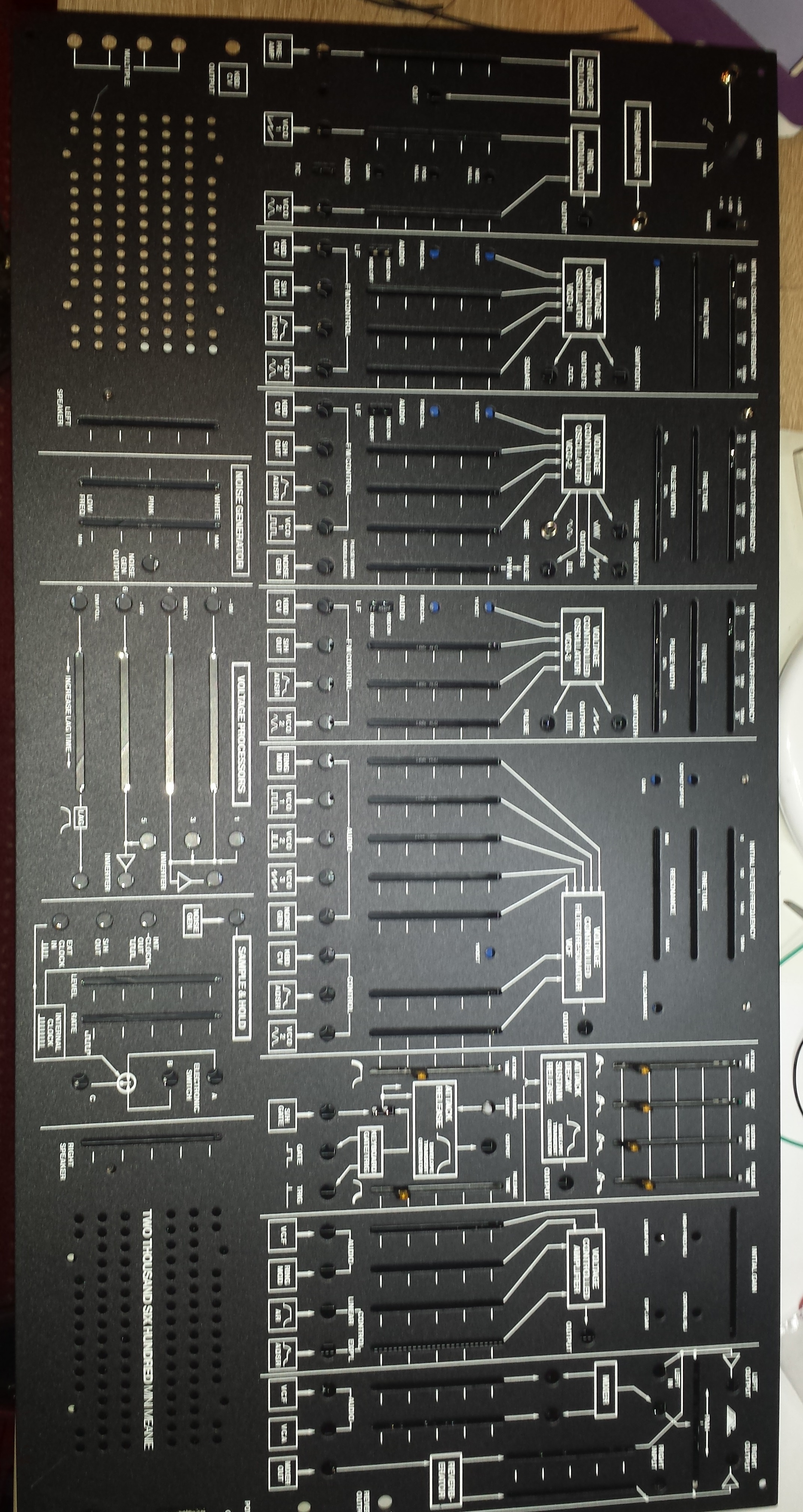
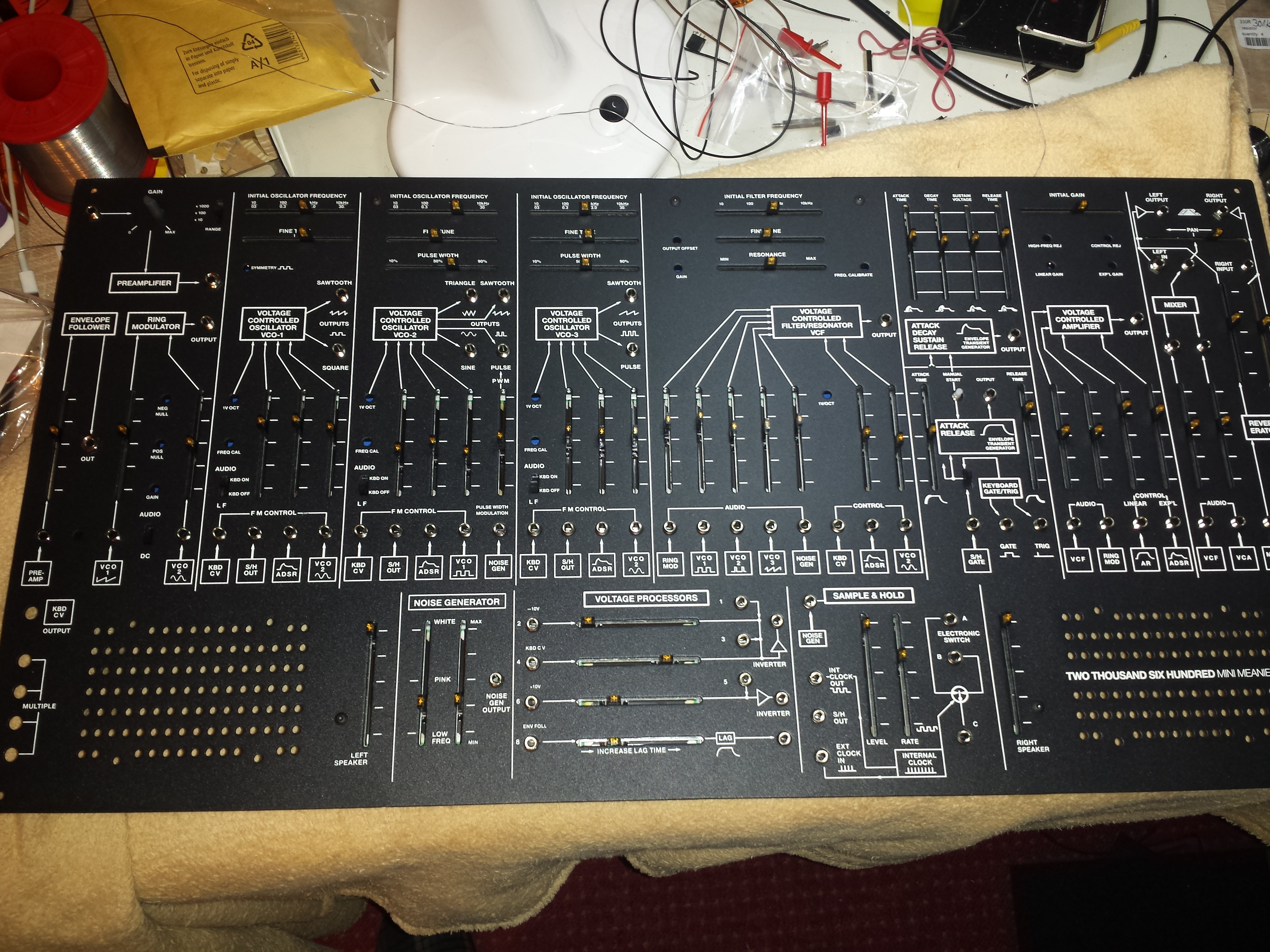
first Panel mounting test
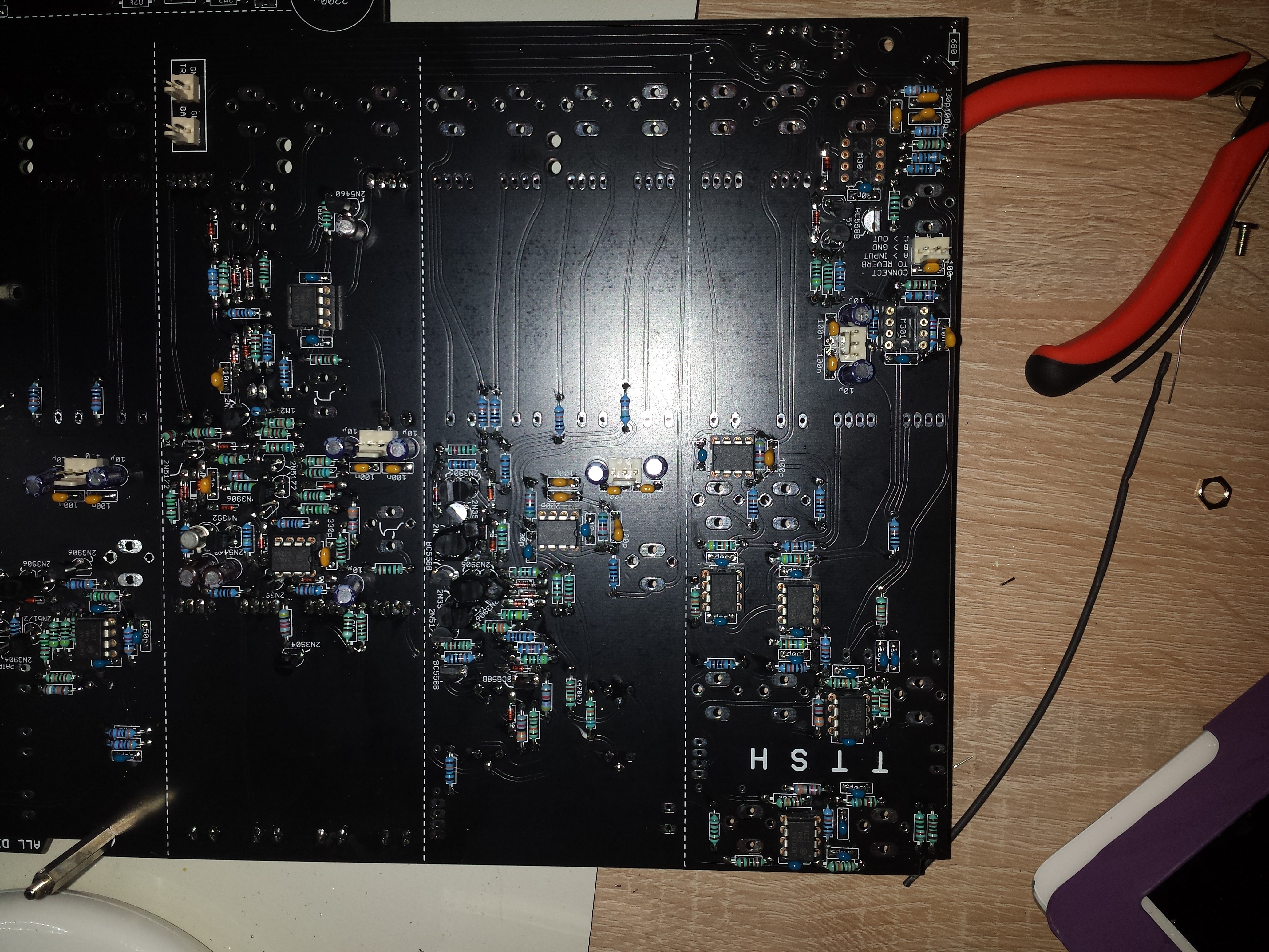
S/H - Clock - Noise
Warning
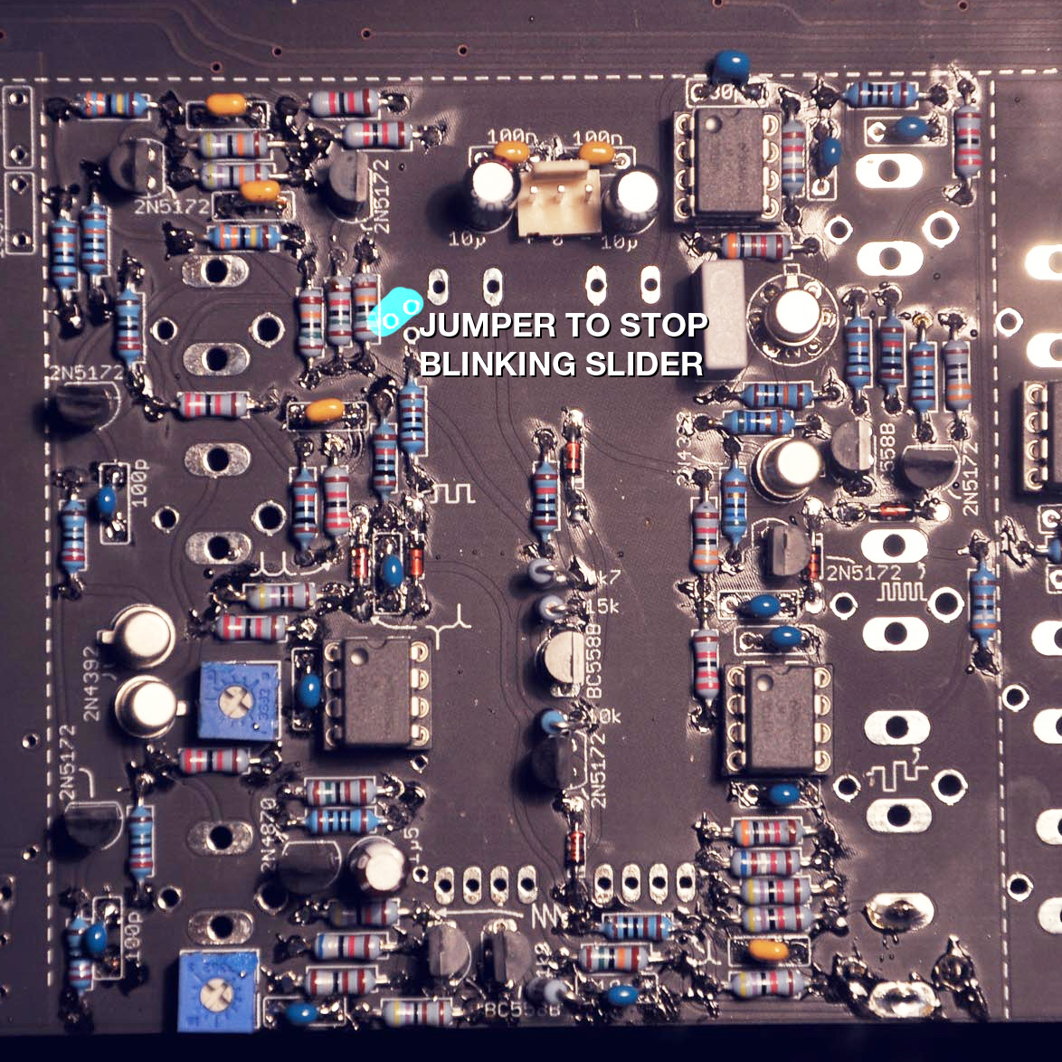
Due to some issues from the clock LED driver - we bridge the 2n5172.
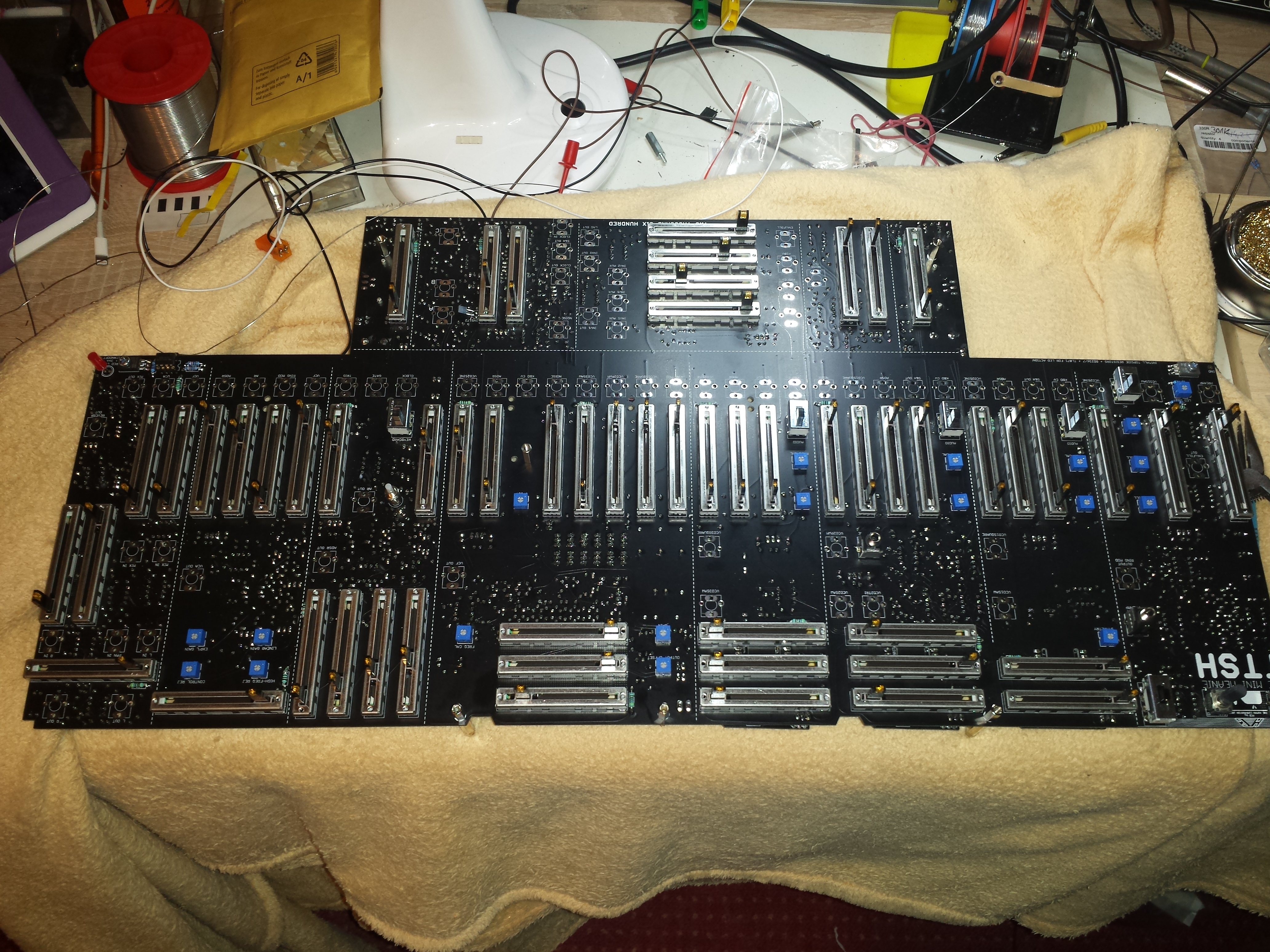
All Parts soldered, Panel mounted, need to solder the jacks.
Build tip:
if you want hear the sound of your TTSH before you have finished the headphone jack wiring,
you have to switch with a jumper the T/TN or R/RN header, otherwise your Amplifier dont have a audiosignal.
Building Tip
place each row of faders on PCB and solder 2 pins, place the Panel in right way and mount all screws,-- solder the Faders complete.
remove the panel and plug all jacks in position, place the panel - mount all screws and few jacks with screws - turn the device, solder the jacks.
solder the LED at last.
Use on all sides spacers, for a faster panel un/mounting use spacers (with plastic/silicon washers) instead of screws and you can turn the panel on table without breaking some faders.
If your NOISE leds and left Volume led dont work.., connect the 470r resistor near amp/noise to the unlabeled solder hole (ground)
its a grounding issue by removing the 10R and cap in power section due to hum issue (described in next step)
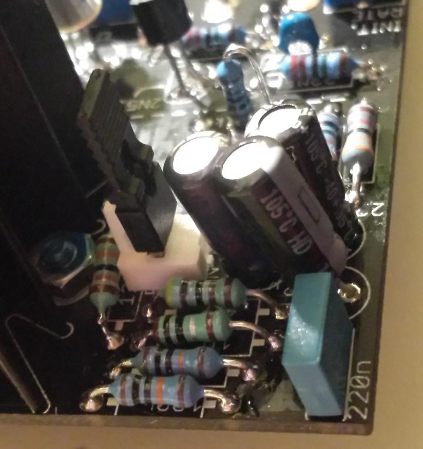
HUM Issue:
by using of both amplifiers for integrated speakers i had massiv hum, by touching the panel the hum sound changes. (hum is only in speakers not in main out)
a workarround from zthee, was tested by me - it helps.
Solutions:
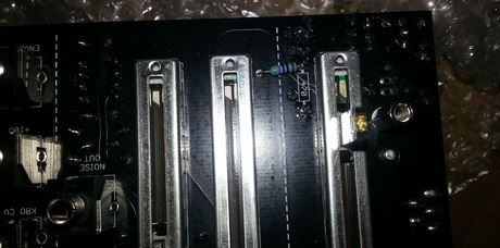
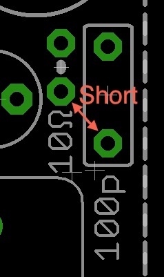
short out the 10Ω resistor and the 100p capacitor in the PSU section. E.g. just make a small bridge between the pad close to 10Ω and 100p as in the attached picture.
use RG174 cables or shielded microphone cable for offboard wiring.
for testing ..
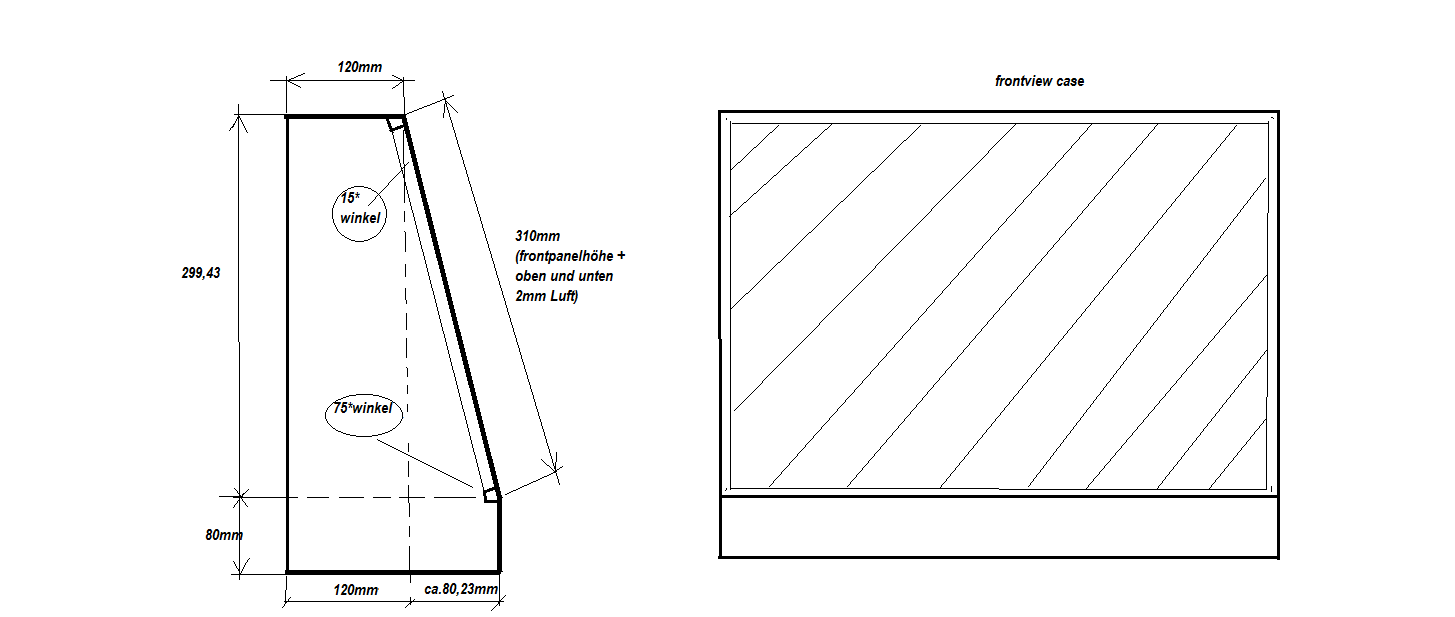
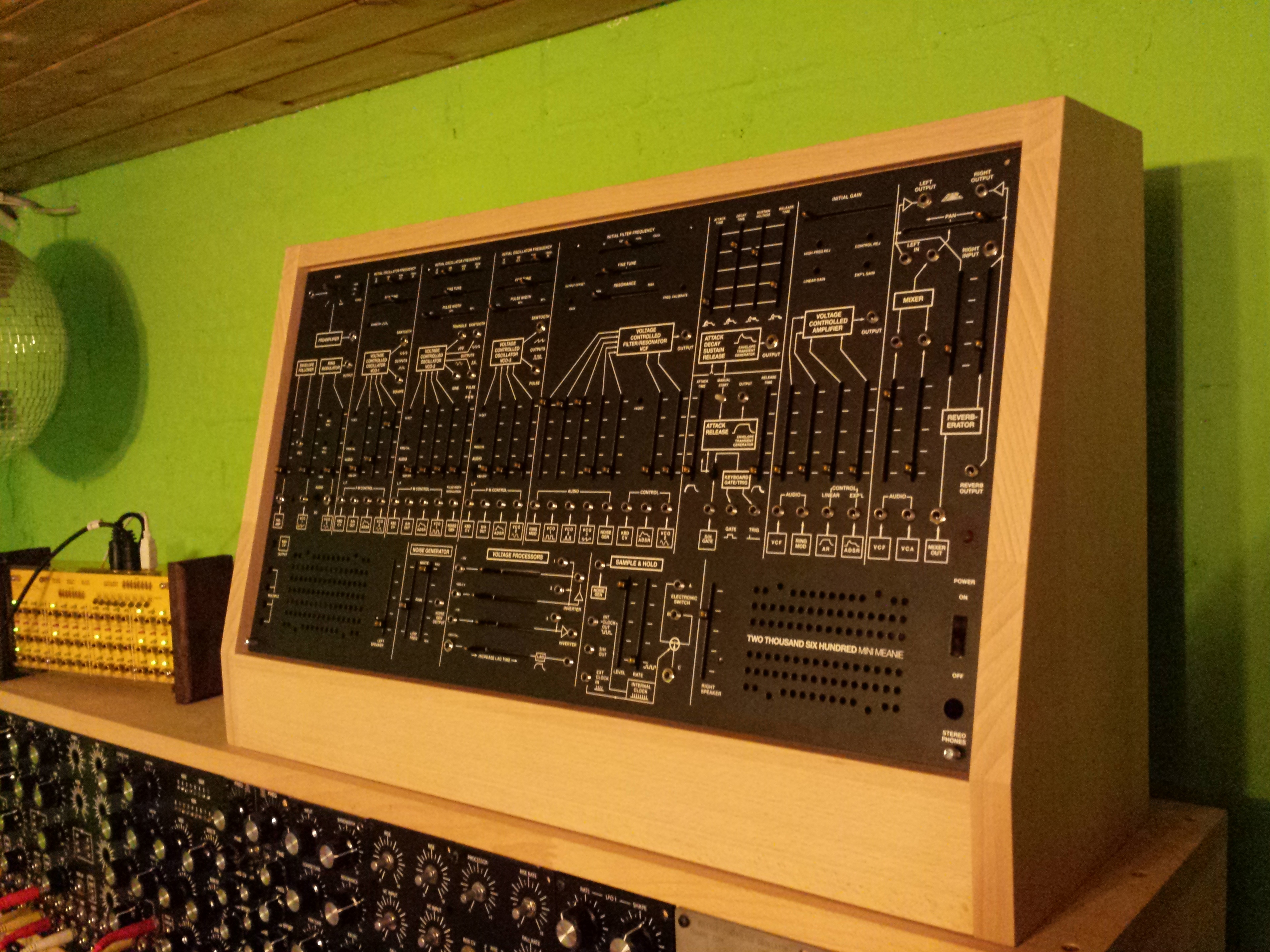
Planned Case:
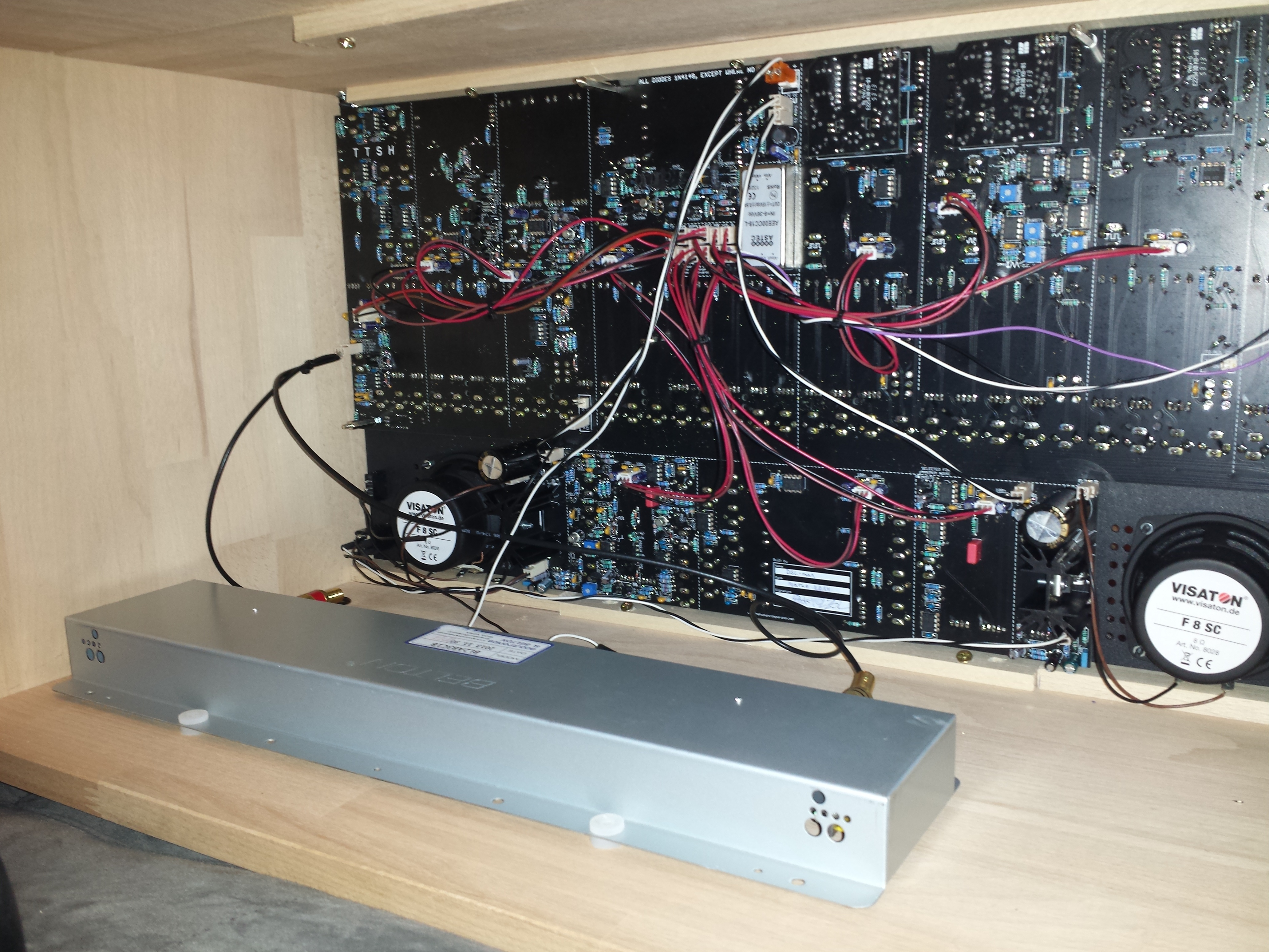
Finalcase..
Mouser cart
https://de.mouser.com/ProjectManager/ProjectDetail.aspx?AccessID=4998691276
please add:
- 1x Powerswitch 633-CWT12AAS1
- 1x BC558 (in sum 9 )
- 1x DC-DC regulator
some missing parts like Transistors, ICs, Reverb Spring, PSU, connectors, jacks and many more:
- Spring reverbs are avaiable from Banzai
- PJ301BM Jacks are avaiable from thonk.co.uk or http://erthenvar.com/store
- Screws are avaiable from me
- for speakers you can use Visaton FC8 /FS8 or similar
Result from Widy/DSL-man:
BOM failure - following parts arent listed
----------------------------------------
1x BC558b S&H missing ( need 9 .. BOM say 8)
1x 150K S&H missing ( not in building doc)
1x100p (missing part )
1x 150K S&H missing ( not in building doc)
1x100p (missing part )
bc337 for noise fix
parts left DSL-man/widy
------------------
1x 47K
2x 100N
optional parts from power input (hum modification)
optional parts from VCO bleed fix (caps)
Here are some important Issues and Fixes from the first batch TTSH pcbs (delivered around March 2014)
other TTSH version known issues are described in the own project sites
update 01.October 2014 VCO2/VCO3 bleed fix
(page links/anchors)
- pcb silkscreen failure for powersupply
- Hum issue on Speaker and more
- Noise "distorted"
- Clock bleed on VCO pitch
- wrong Silkscreen for matched pairs
- wrong Silkscreen or polarity for Capaciator C20
- VCO Bleed - Regulator
- not all LEDs are working
- LED Dimming Fix
- VCO2-VCO3 Bleed fix
Solutions:
![]() = tested
= tested
![]() = untested
= untested
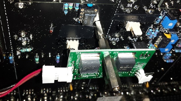
FIX for pcb silkscreen failure for powersupply 
cross one Ferrite on top pcb side - the ferrite on other pcb site (not shown here)
other way:
FIX for Hum issue on Speaker:
This Issue occurs by using the internal DC-DC Adapter,
FIX: short out the 10Ω resistor and the 100p capacitor in the PSU section. E.g. just make a small bridge between the pad close to 10Ω and 100p as in the attached picture.
further use RG174 cables or shielded microphone cable for offboard wiring.
make Attention on resistor 470R on frontside - see here (LEDs dont work)

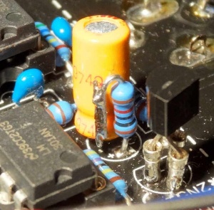
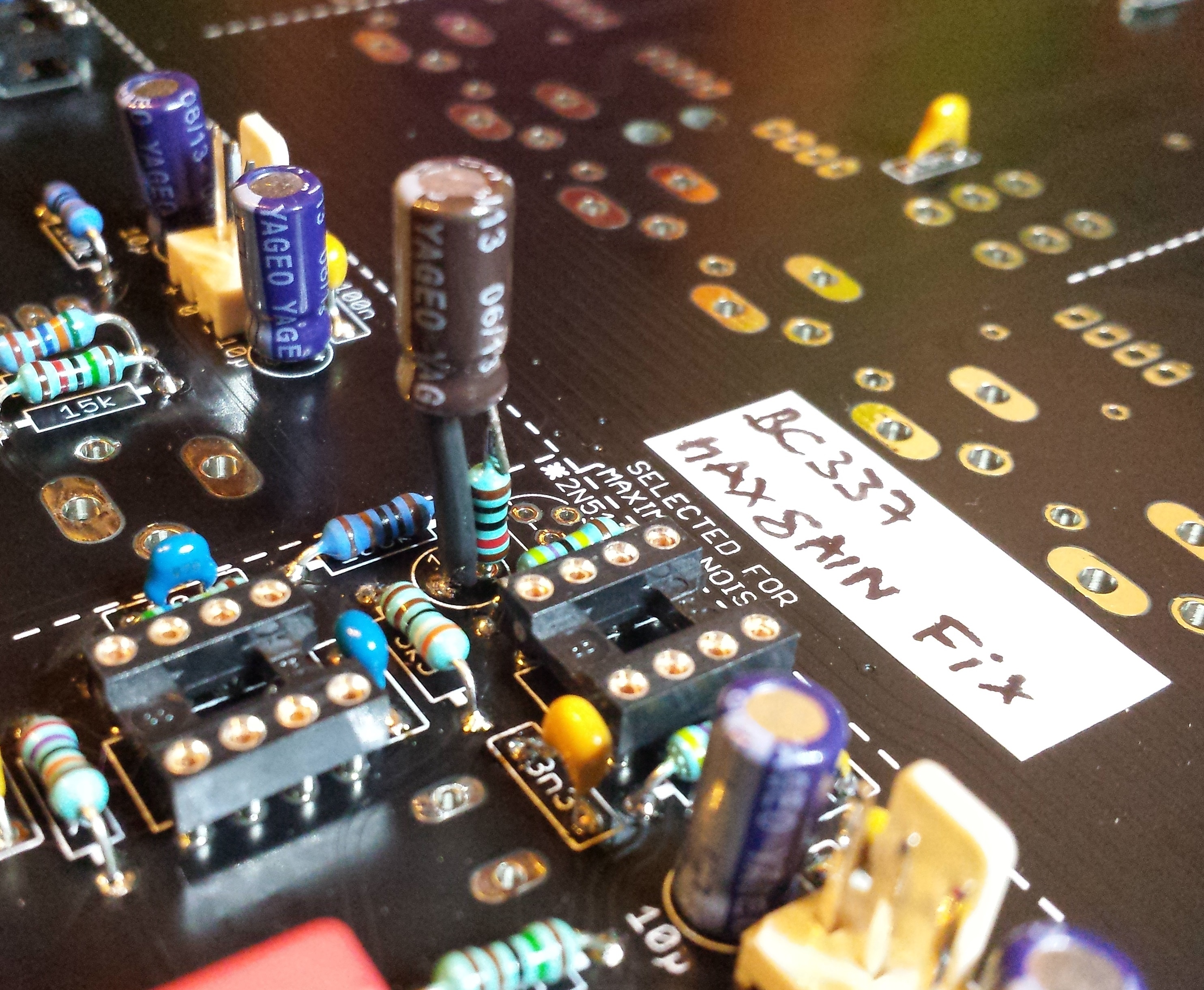
FIX for distorted Noise.
Option A: the easiest way is the usage of a BC337-16 with folllowed orientation, there´s no need for addional parts.

Option B (from nordcore)
leave out the 2n5172 - use a bc337-40, - bend right leg to top, solder a 10K resistor in series to the 1uF cap.
see here to choose the correct BC337: https://www.muffwiggler.com/forum/viewtopic.php?p=1558920&highlight=#1 558920

Option C: (same like Option B)
other working solution howto connect a 10K resistor to the cap (after soldering, use shrinktube for cap and resistor housing )
leave out the 2n5172 - use a bc337
FIX for Clock bleed on VCO pitch
at the moment 2 steps to fix the Issue - (both together must used to fix the Issue)
First Step - tested solution ![]() : leave out the 2n5172 in clock section (led driver for blinken lights), bridge 2 solder holes..
: leave out the 2n5172 in clock section (led driver for blinken lights), bridge 2 solder holes..
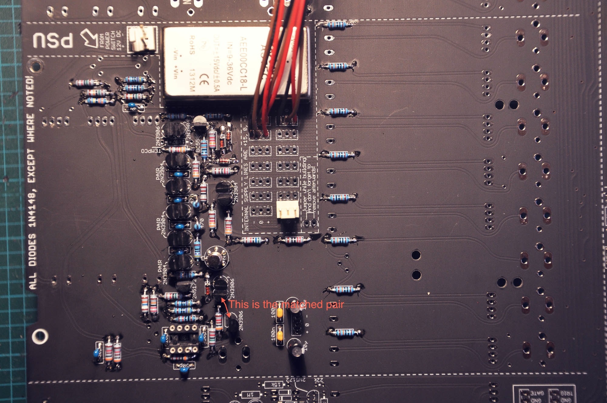
FIX for wrong Silkscreen for matched pairs Transistors in Filter section
the top 2n3906 is unmatched, you have to take 3 matched transistors if you´re not really sure about it.
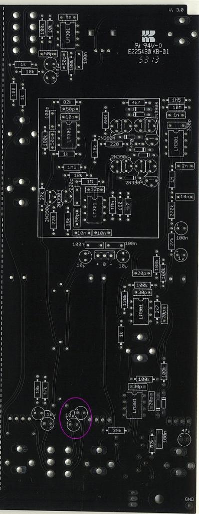
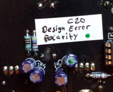
FIX for wrong silkscreen or polarity for capaciator C20 in RINGMOD section valid
change the polarity of C20 10µF elecrolytics (its the right hand capaciator)
VCO Regulator:
due to VCO Bleed issues, Nordcore from muffwiggler sales VCO Regulator pcbs, this fix this issue. approved ![]()
- build the VCO regulator
- desolder or cut the MLCC 100N from the power inputs on all 3vcos and from voltage processor, the 10uF caps can leave out too (but its okay to have this)
- drill a hole in pcb to mount by a 10/12mm spacer the pcb.
- put a further spacer on the 10/12mm spacer for calibrating the VCO regulator (dont connect the regulator to the vco header yet.
- connect only power input to regulator and set it to 14,6V (TP1+ TP2, TP1+TP3)
- unmount the second spacer and place the regulator in MTA header for final calibration/further tesing/building.
Issue: not all LED´s are working
Solution: turn the Trimmer LED- trimmer in the left bottom corner (frontpanel view)![]()
(in my case LEDs dont glow in VCA section, otherwise connect the 470R to right (issue occurs by using Hum bug fix, in result no ground for LED´s in noise and left amp section )

LED Dimming Fix:
due to section by section LED-Fader power consumption is not balanced - you cant dim the TTSH LEDs to a common balanced LED brightnessRegarding the LEDs: due to the uneven length of the LED chains there is only one dimmer setting possible, where all are equal bright - if the resistors are properly calculated.
from muffwiggler you can order or build a own pcb or build your own:
ttsh_led_resistor_182.rar (BRD file)
Idea:
http://www.muffwiggler.com/forum/viewtopic.php?p=1566660#1566660
pics of all locations: ttsh-leds.zip
Solution:
Fixing the dimmer to dim all LEDs uniform requires some effort:
- the longest chain with 5 LED must be split. (Two traces to cut, two wires to solder. Resulting in two chains with four LEDs instead of one 5 and one 3. )
- all chains shorter than 4 LEDs get one or two additional orange LEDs in row to the resistor, so all are 4 LEDs long.
- all resistors get the same value (200 to 240 Ohms)
Replace the 1kOhm base resistors (LED-R3, LEDR6) with 100 Ohms. (They are not needed (straight wire would be ok), but having a resistor enables you to measure the base current and gives some fault protection. 1k gives nearly 1V drop, too much for proper current setting with resistors. )
So now all rows have the same current, at *all* dimmer setting (not just at one).
The current can be adjusted to nearly full brightness of the LEDs. (16mA or so. )
The dimmer can be set to all LEDs off.
Traces to cut:
http://dl.dropboxusercontent.com/s/birte0zg922kt22/ttsh-cut-leds.jpg
Wires to solder:
http://dl.dropboxusercontent.com/s/u0igpajfoh54o27/ttsh-wire-leds.jpg
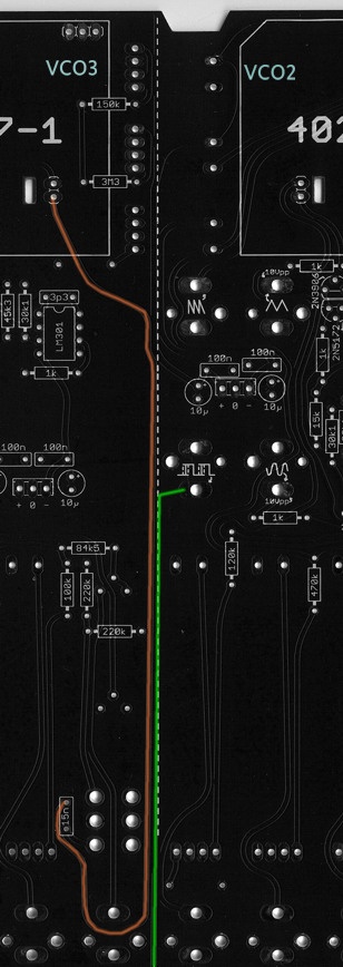
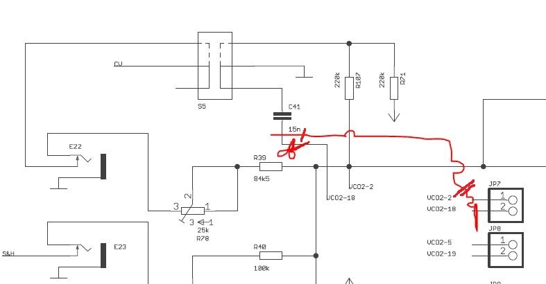
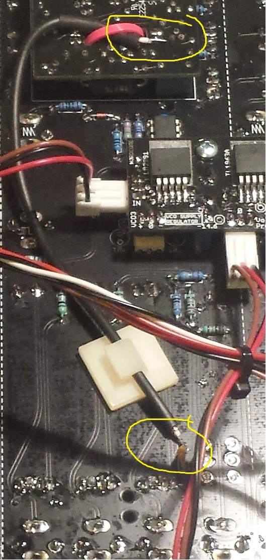
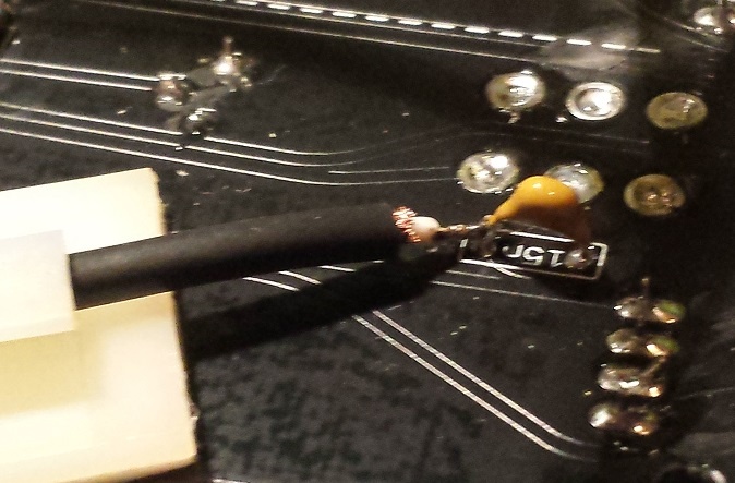
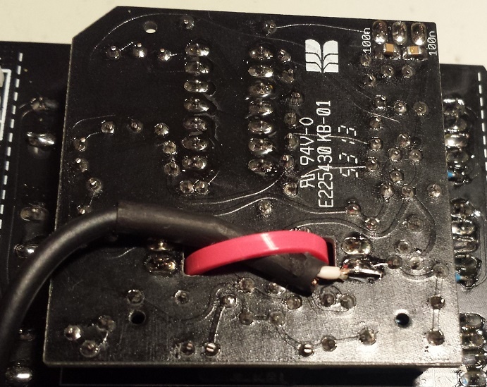
VCO2-VCO3 Bleed
Issue: VCO3 is modulated by VCO2, due to interferences of 2 traces (on the pcb 2 traces run very close)
Solution:
cut the orange trace near 15N cap and vco3 Submodule header on pcb, run a shielded cable like RG174 from 15N to VCO3 submodul.
wire a ground to shielded cable shielding
TTSH hardcore builders guide (specially rev.1)
update: 01.October2014 - jumpers, speaker workaround for testing
The first TTSH was build with zthees Builders Guide and works fine, but its not effective to solder section by section.
from my second TTSH on I built them after these steps:
- add both jumpers, kybdCV/GND and near the ferrite beads
- sort out all resistors in values: 1R - 999R, 1K - 9K, 10K-99K, 100K-999K, 1M-22M , same with capaciators.
- take a label/sticker on places where you have MODS/bugfixes like c20 cap, noise mod etc..
- put the TTSH pcb on 25-30mm spacers (use the BD236/BD237 holes too for spacers) you have to mount a spacer on each side of the pcb so you can turn the pcb for soldering..
- build the complete VCO- Subboards (so you don't have to look for missing resistor points on the main pcb all the time)
- solder all IC sockets on both sides of the pcb (LED IC on the other side of the pcb)
- solder all voltage connectors (MTA´s) in the powersection, key cv, speaker etc.
- put all resistors in place on the main pcb, start with the highest amounts; (more than 60 x 100K) ... if you'll have completed nearly 80% and it'll be easier now to put the rest in place section by section.
- solder all resistors from the top
- turn pcb and cut all pins/legs - this way you can solder all pins/legs in one step..
- if you have a VCO voltage regulator from nordcore, put a tape over the 100nF/10uF caps near the power MTA header.
- Capaciators - begin with 100nF c0g for the audio path, followed by 100nF for the rest,and then all the other caps.. pay attention on the filmresistors... I use film caps (wima) for the VCF near matched trannys which makes the Filter sound really good.
- solder all caps from the front/rear.. keep attention on the C20 cap
- put all diodes and trannys in place ..(pay attention on c20, max noise fix, bridge instead of 2n5172 in clock, in VCF matched, sont mount the Amp. cooling blocks
- put all the LM301 in the IC-sockets
- build the VCO header connection for all 3 VCOs..
- unmount the 25-30mm spacers and replace them with the final 12mm spacers and screws..
- solder all faders, begin with 1 solderpoint on every side, put the frontpanel on the pcb and check the fader orientation. - alternative: bend one leg on each side and solder one point only
- check the orientaion
- finally solder all the faders..
- Jacks: solder on each corner 1-2 jacks, and 3 in middle, place the panel and then solder them
- then place all jacks, put the panel on top and mount the nuts on the jacks in the corners, then turn the panel, now you can solder all the jacks..
- switches.. unmount the panel, put all switches in place and mount the panel, turn the panel/pcb .. the switches fall in place, solder a bit.. turn the panel and check the orientation on the frontpanel, if it is good , solder finally ( please check the mechanical function of the switch before you mount them, sometimes you have faulty switches and its hard to desolder them..)
- *update 01.October 2014 : if you want to test the TTSH with speakers but without the headhone jack wiring add a jumper to TN/ T or RN/R otherwise your speaker won't work.
- build the power wiring cables and solder the internal DC-DC adapter..
- initial check : disconnect all sections, check the voltage near DC-DC adapter with a DMM .
- if you have a VCO regulator, build it, put it on the powerheader, drill a hole in the pcb and mount a spacer,calibrate the regulator to 14,6V
- test and calibrate the TTSH - good luck