Project
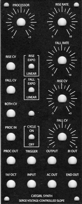
Projecttitel:cgs75 Serge VCS in MOTM
Status:FINISHED
Startdate: 28.02.2014
Duedate: 02. July 2014
Manufacture link: http://cgs.synth.net/
related articles:
http://electro-music.com/forum/post-281432.html
BOM:
| Part | Quantity |
| Capacitors | |
|---|---|
| 47pF | 9 |
| 1n | 2 |
| 10n | 2 |
| 22n | 1 |
| 100n | 6 |
| 10uF 25V | 2 |
| 47uF 25V | 1 |
| Resistors | |
| 100R | 1 |
| 330R | 2 |
| 1k | 2 |
| 1k8 | 1 |
| 2k2 | 3 |
| 8k2 | 1 |
| 33k | 2 |
| 68k | 1 |
| 82k | 5 |
| 100k | 18 |
| 150k | 1 |
| 200k | 1 |
| 220k | 4 |
| 330k | 3 |
| 470k | 2 |
| 600k | 1 |
| 820k | 4 |
| 1M | 9 |
| 10M | 2 |
| 100k trimmer | 1 |
| 50k lin pot (FALL,RISE POT | 2 |
| 20k lin pot for processor | 1 |
| 100k lin pot (CV-pots) | 2 |
| Semi's | |
| LED | 1 |
| 1N4148 | 6 |
| 2N3904 | 3 |
| 2N3906 | 3 |
| 5V6 400mW Zener | 1 |
| TL071 | 1 |
| TL072 | 2 |
| TL074 | 1 |
| LM3900 | 1 |
| Misc. | |
| Ferrite Bead | 2 |
| SPST switch | 3 |
| 0.156 4 pin connector | 1 |
| CGS75 PCB | 1 |
| Panel Bridechamber | 1 |
| PotBracket - own | 1 |
Wiring:
| ac out | ac out jack |
| bo | bi-polar output jack |
| out | out jack |
| trig in | trigger in jack |
| cy sw | (x 2) cycle switch. Switch connects these together for cycle mode |
| end | end out jack |
| rrw | rise rate wiper |
| CW end of rise rate pot connects to +ve | |
| CCW end of rise rate pot connects to 0V | |
| frw | fall rate wiper |
| CW end of fall rate pot connects to +ve | |
| CCW end of fall rate pot connects to 0V | |
| exp | exponential cv jack |
| rise cv | rise cv jack |
| both cv | both cv jack |
| in | input jack |
| swf | (x 2) fall switch. Switch connects these together for exp. response. |
| swr | (x 2) rise switch, Switch connects these together for exp. response. |
| rw | rise pot wiper |
| rccw | rise pot counter-clockwise |
| rcw | rise pot clockwise |
| fcw | fall pot clockwise |
| fccw | fall pot counter-clockwise |
| fw | fall pot wiper |
| fcv | fall cv jack |
| pout | processor output jack |
| pccw | processor pot ccw |
| pcw | processor pot cw |
| pr1 | processor input |
| pr2 | processor pot wiper |
Setting up - Calibration
Adjustments on the VCS board are set to obtain a 0 to +5 volt level when the unit is cycling, producing a 100Hz triangle wave. An oscilloscope is required for this adjustment. In an oscilloscope is not available, adjust for the least distorted sounding waveshape.
Schematics:
keep attention on the Processori input jack with 200K resistor at the jack switch to +V.
also make sure you have all 3 "bridges" correctly filled with a piece of wire or rest from a resistor leg, otherwise the module dont work correct.
| There are no images attached to this page. |