Here starts my own Building Documentation /Steps and Modification.
last Modification Date: 21 May 2014
BOM from me: BOM TTSH modificated
Dokumentation: http://thehumancomparator.net/building/
pdf. Dokumentiton and calibration guide (at the end) : http://www.guyd2.com/ttsh-buildpocket.pdf (doublecheck the PSU/Polarization issue)
Schematic: TTSH-schematics.pdf (also avaiable on zthees webserver)
STATUS completely finished
ATTENTION - wiring from PSU to the module headers are wrong "silkreen error" +/- must crossed - doublecheck before power up modules
Please read the Buildings tips to save time
Dont solder switches, Pushbutton, faders and jacks prior finally assembly - the orientation is only correct by placing all jacks/faders..
The board and pcb bends if you solder all fader and jacks without a case, put the panel on spacers or in a case.
(see at bottom for more infos)
Result from Widy/DSL-man:
BOM Failure - parts not listed
----------------------------------------
1x BC558b S&H missing ( need 9 .. BOM say 8)
1x 150K S&H missing ( not in building doc)
1x100p (missing part )
1x 150K S&H missing ( not in building doc)
1x100p (missing part )
parts left DSL-man/widy
------------------
1x 47K
2x 100N
first TTSH Kit arrived on 05.03.2014
TIP: check the pcb for failures !

Starts soldering the VCO Boards:
Online building documentation failure:
for VCO pcbs in zthees building website shows 1x61k9 but needed on each pcb 2x 61k9 resistors
http://thehumancomparator.net/4027-2/


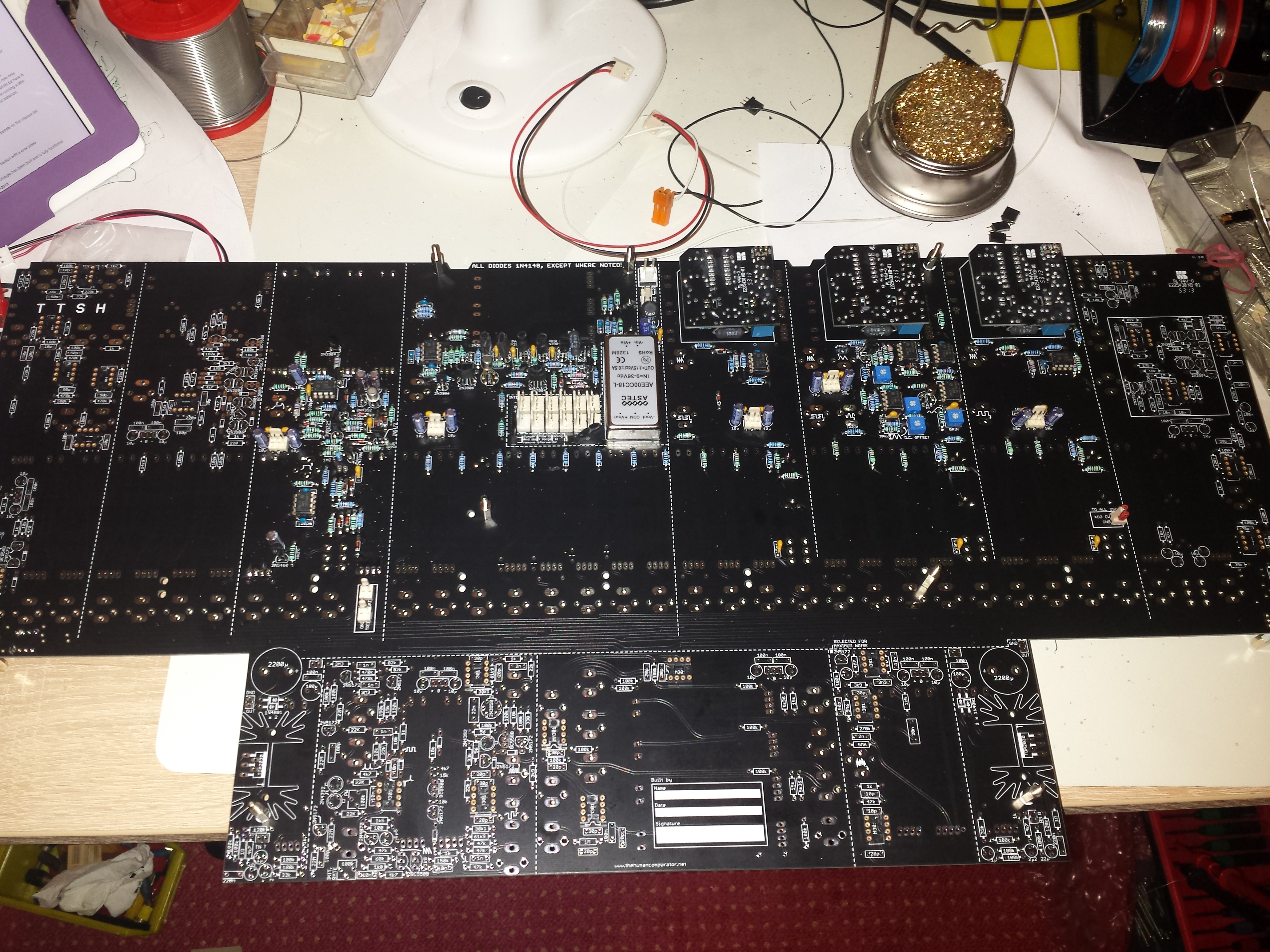
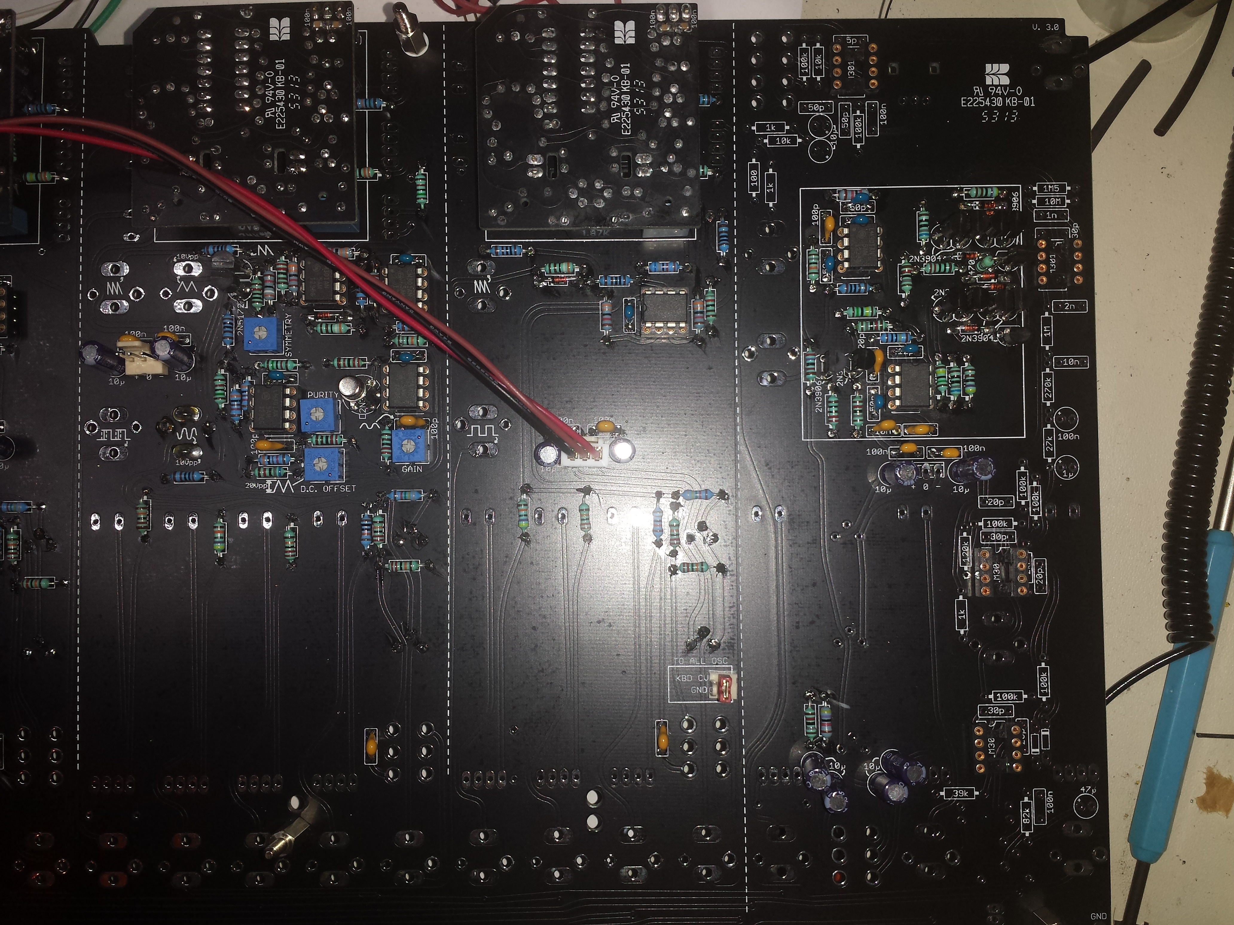
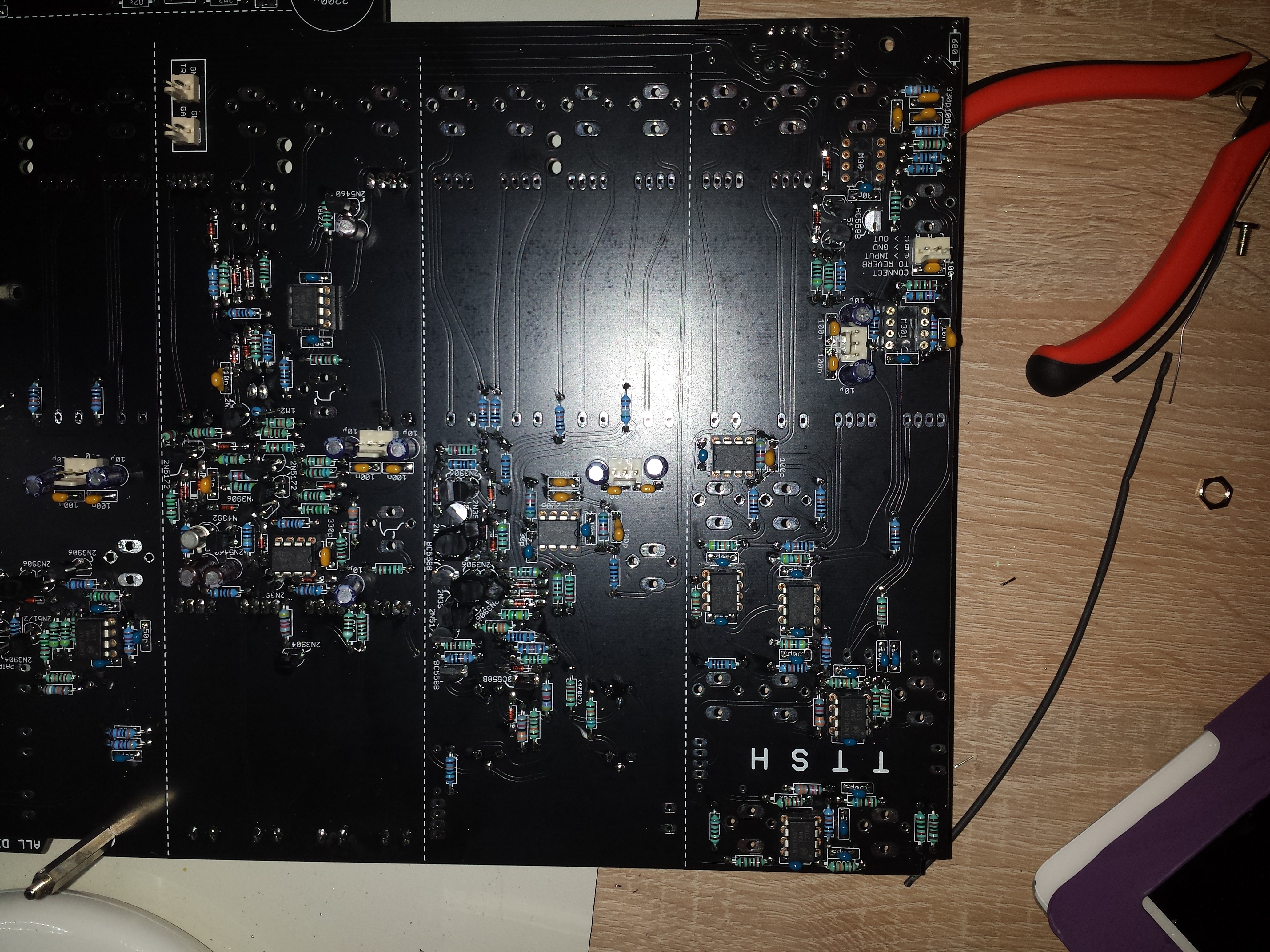
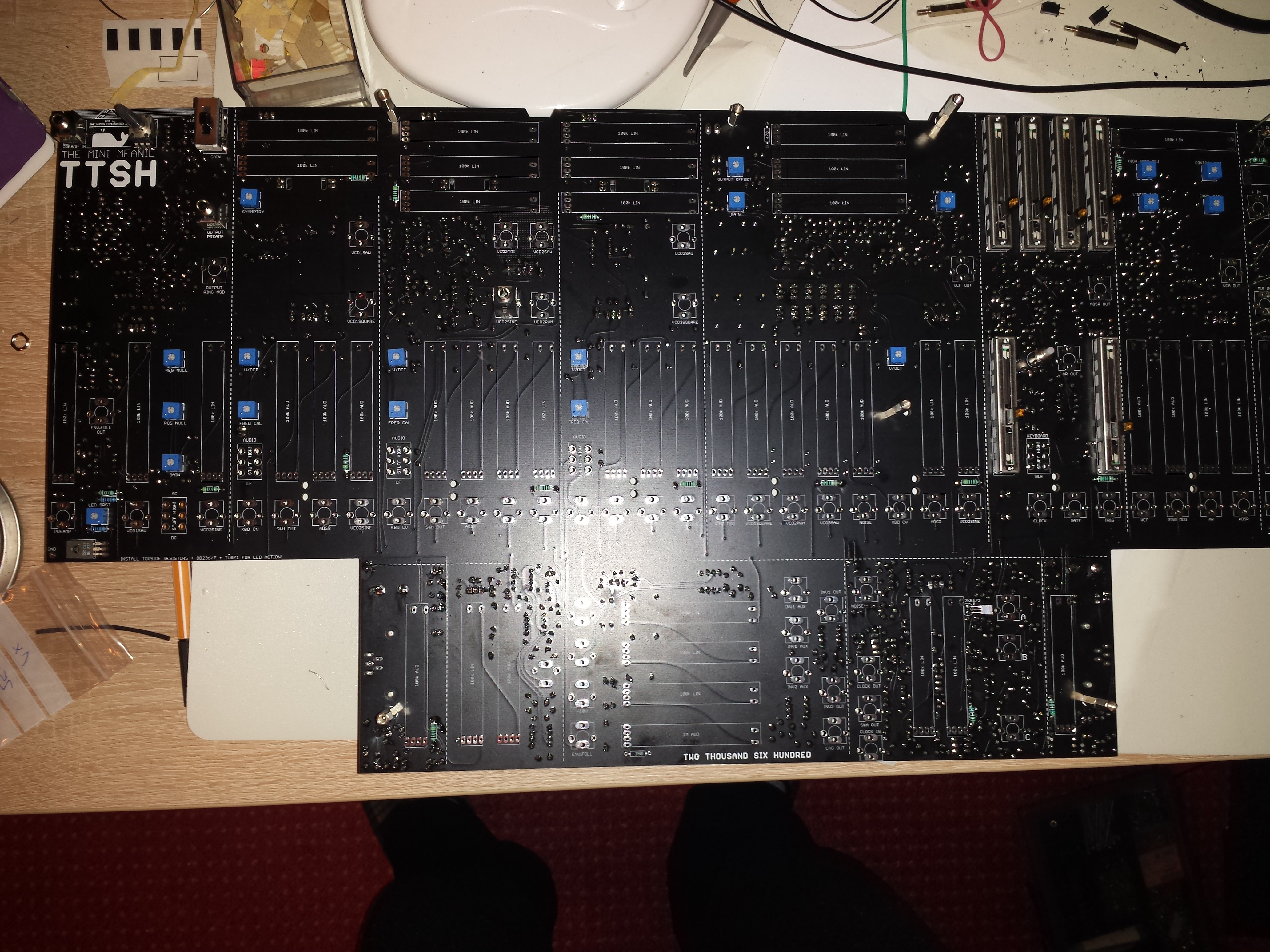
Start assembly Main PCB
Use standoffs/Spacers:

Mounting VCO-1 pcb with long headers, but solder before 150K & 3m3
( i use only long headers)


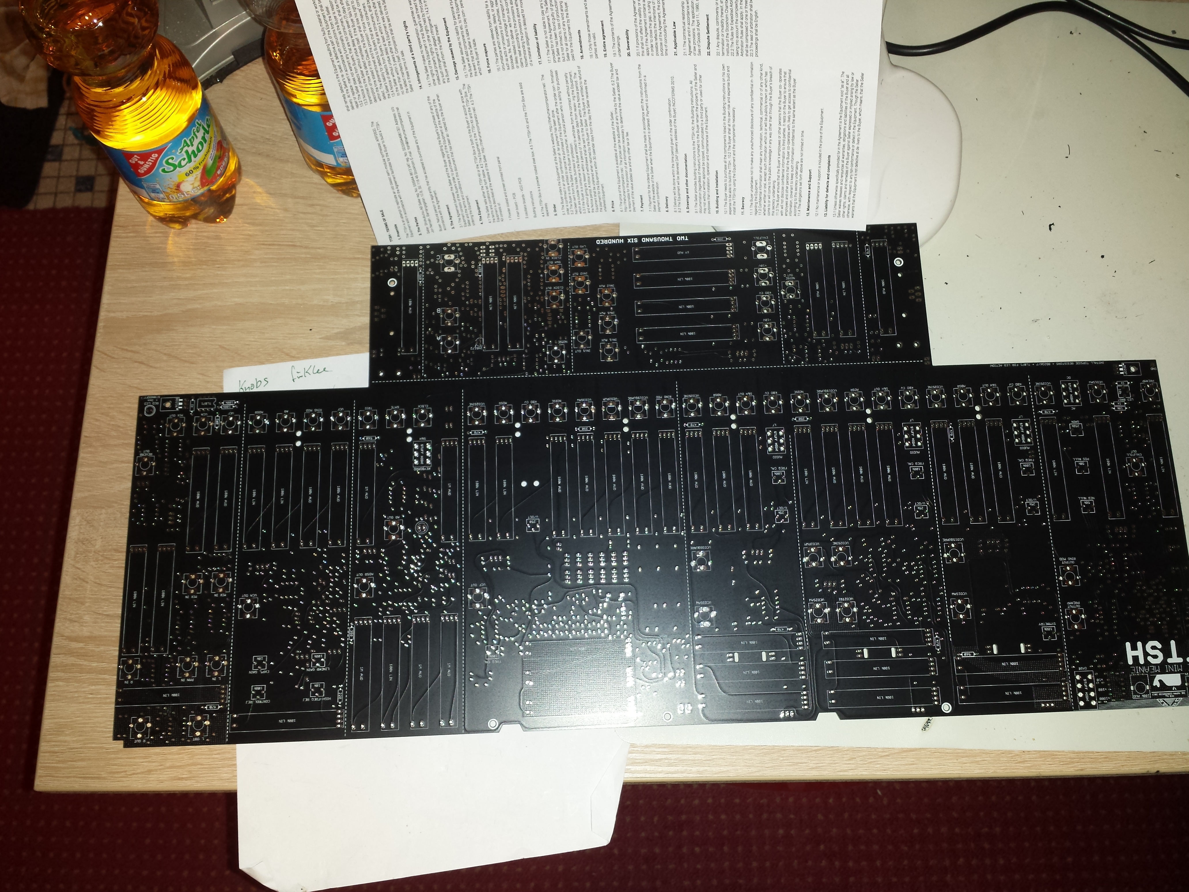
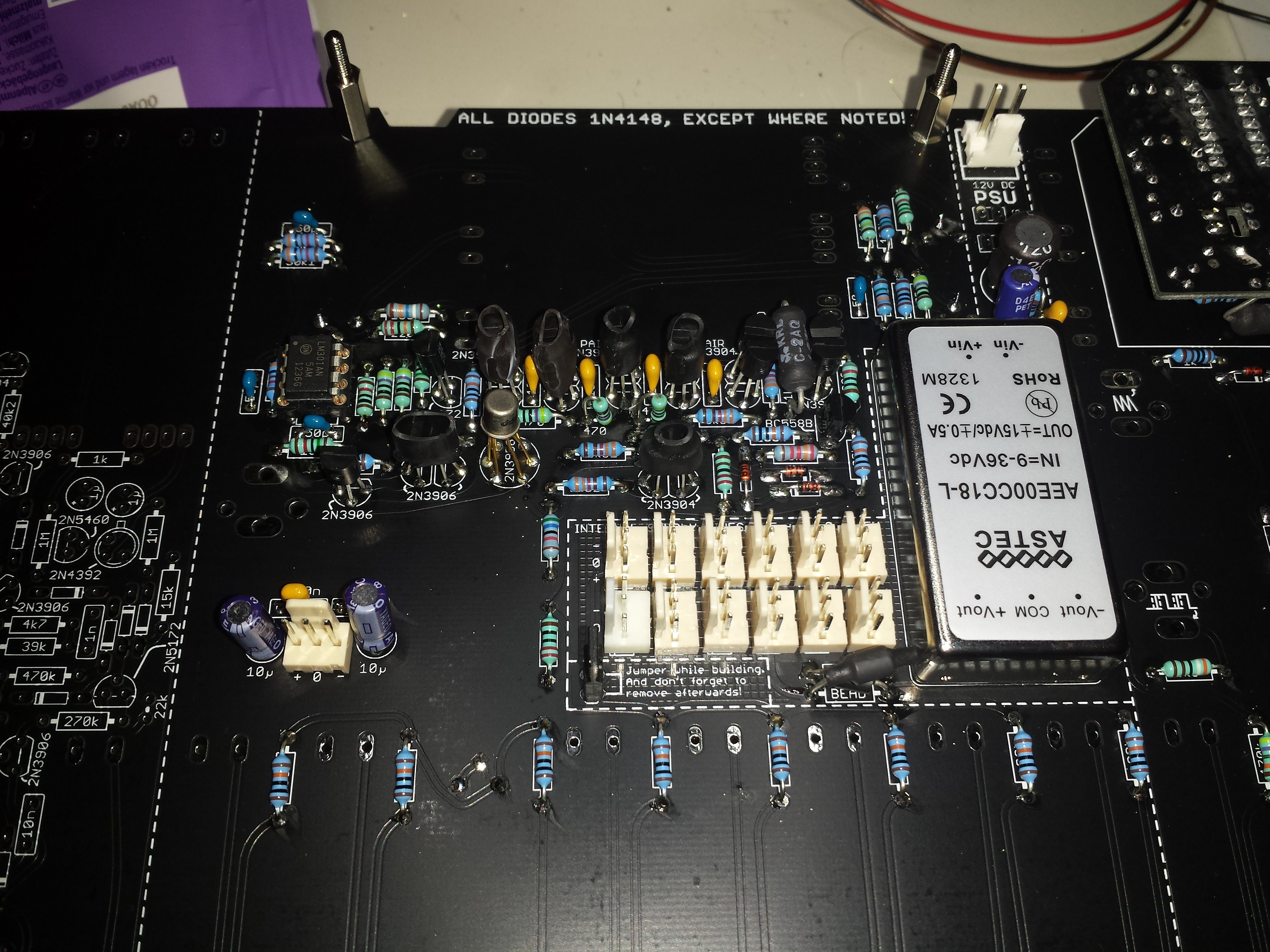
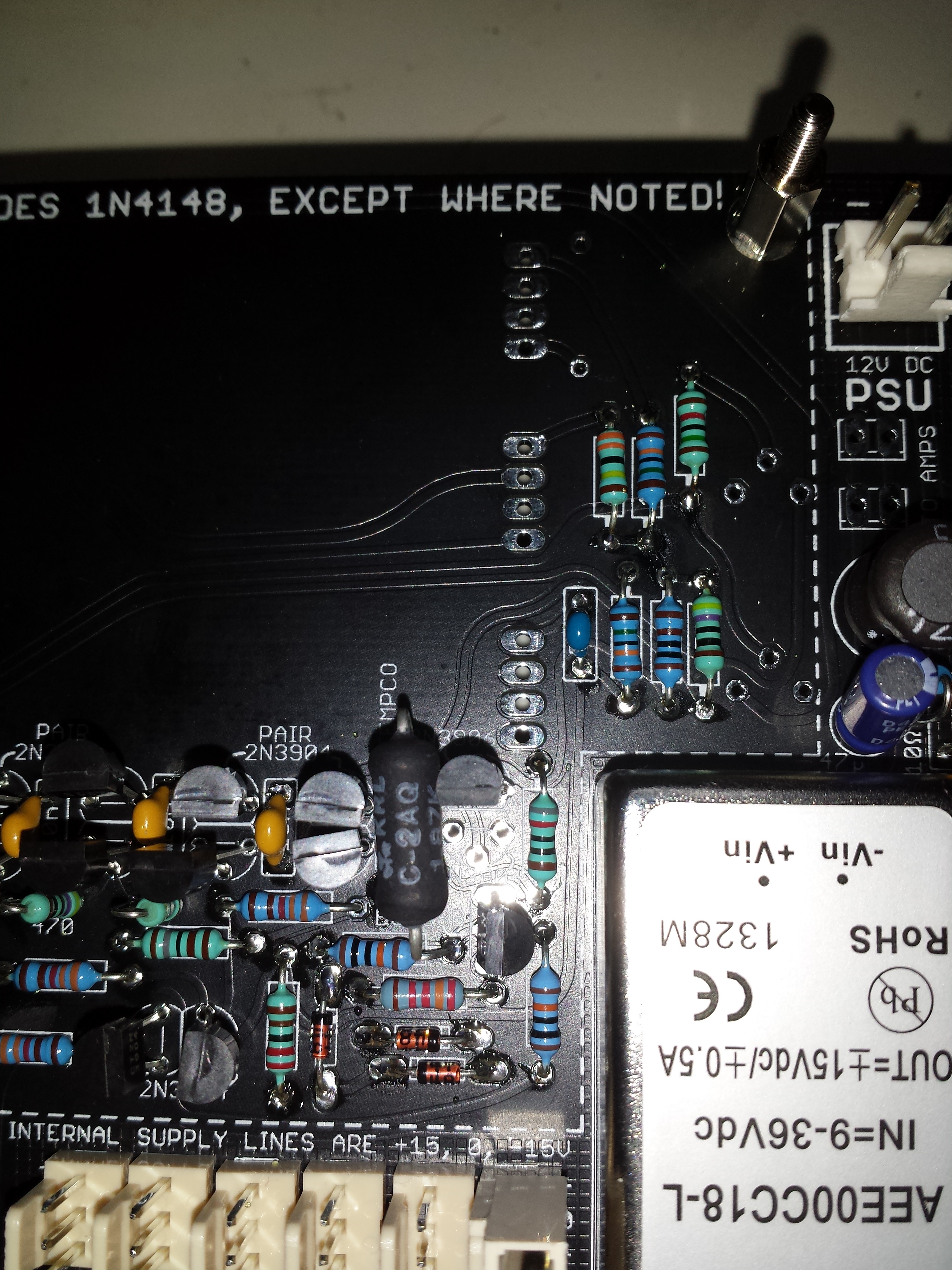
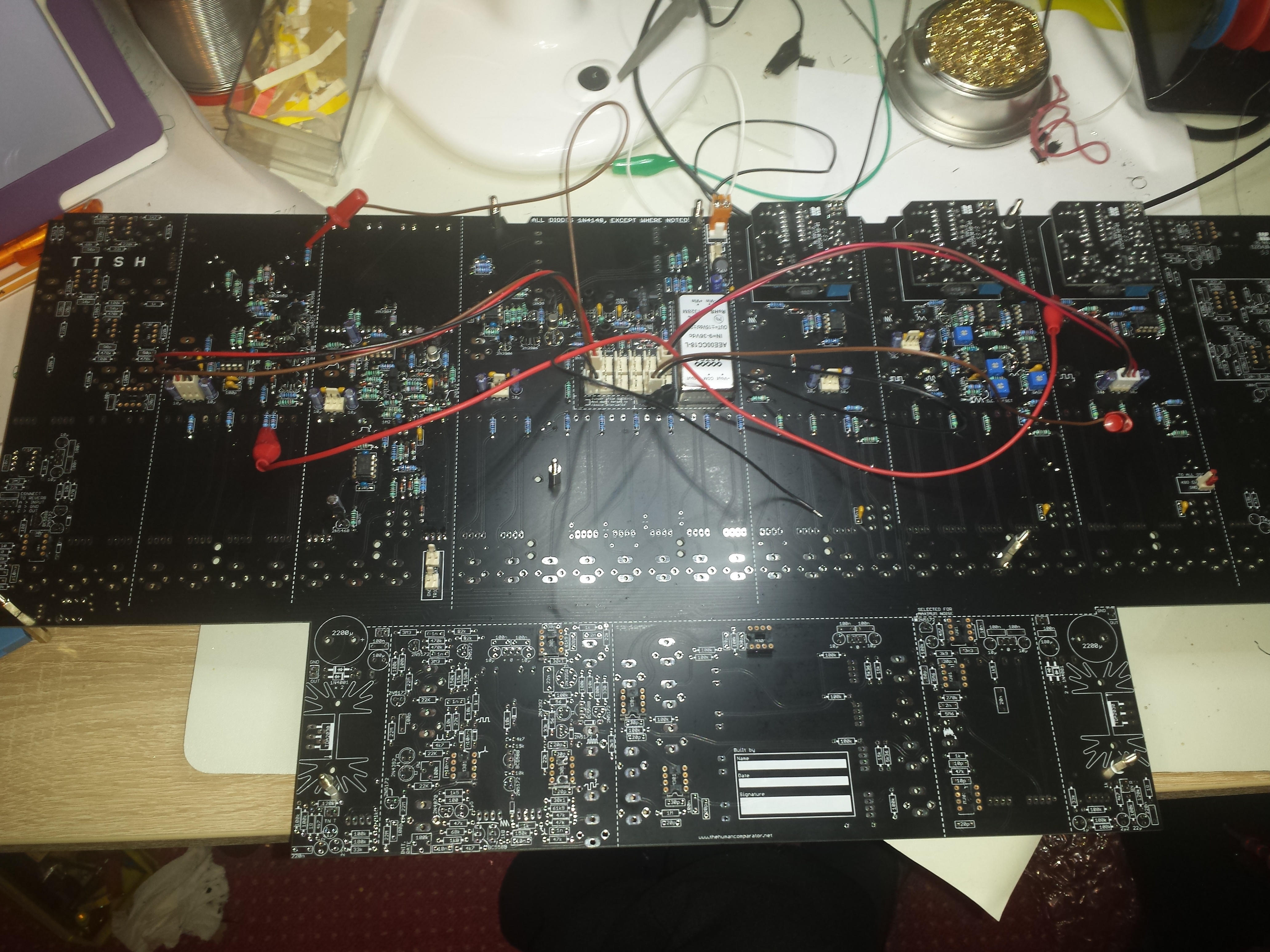
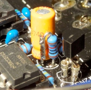
PSU with DC-DC Voltage "regulator"
right picture shows the X-crossed ferrite bead to fix the -15/+15V silkscreen error,
cross one Ferrite on top pcb side - the ferrite on other pcb site (not shown here)

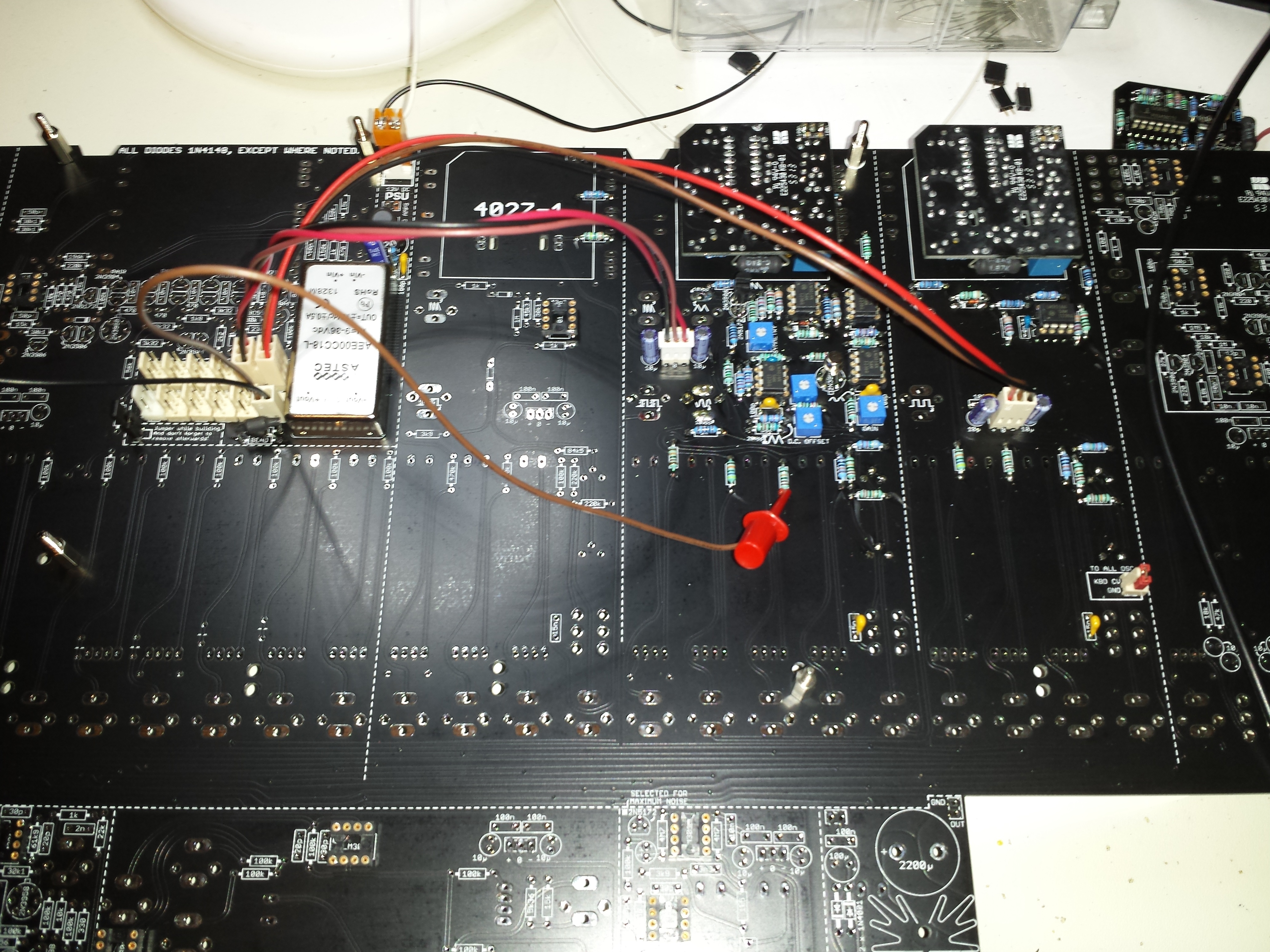
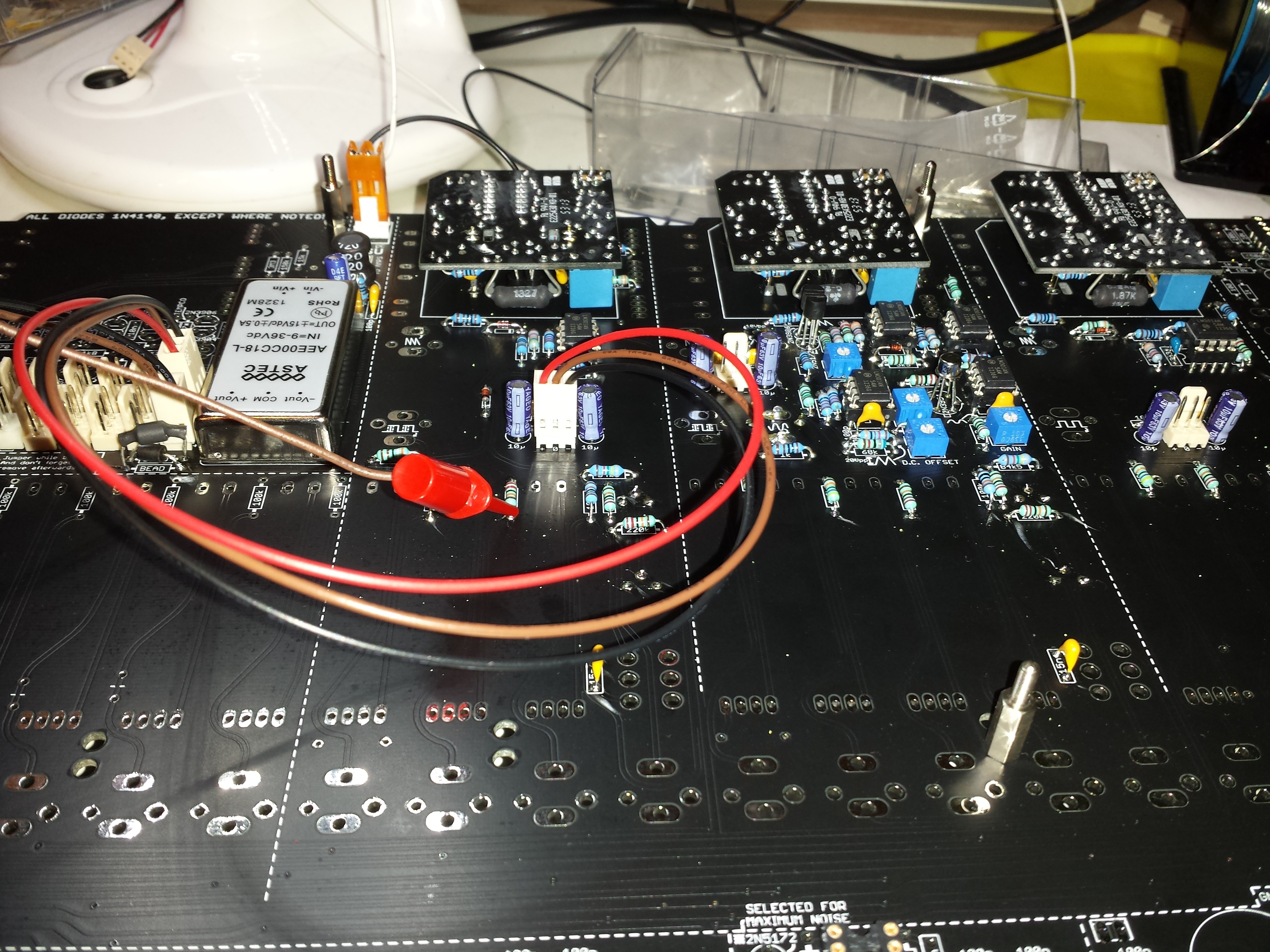
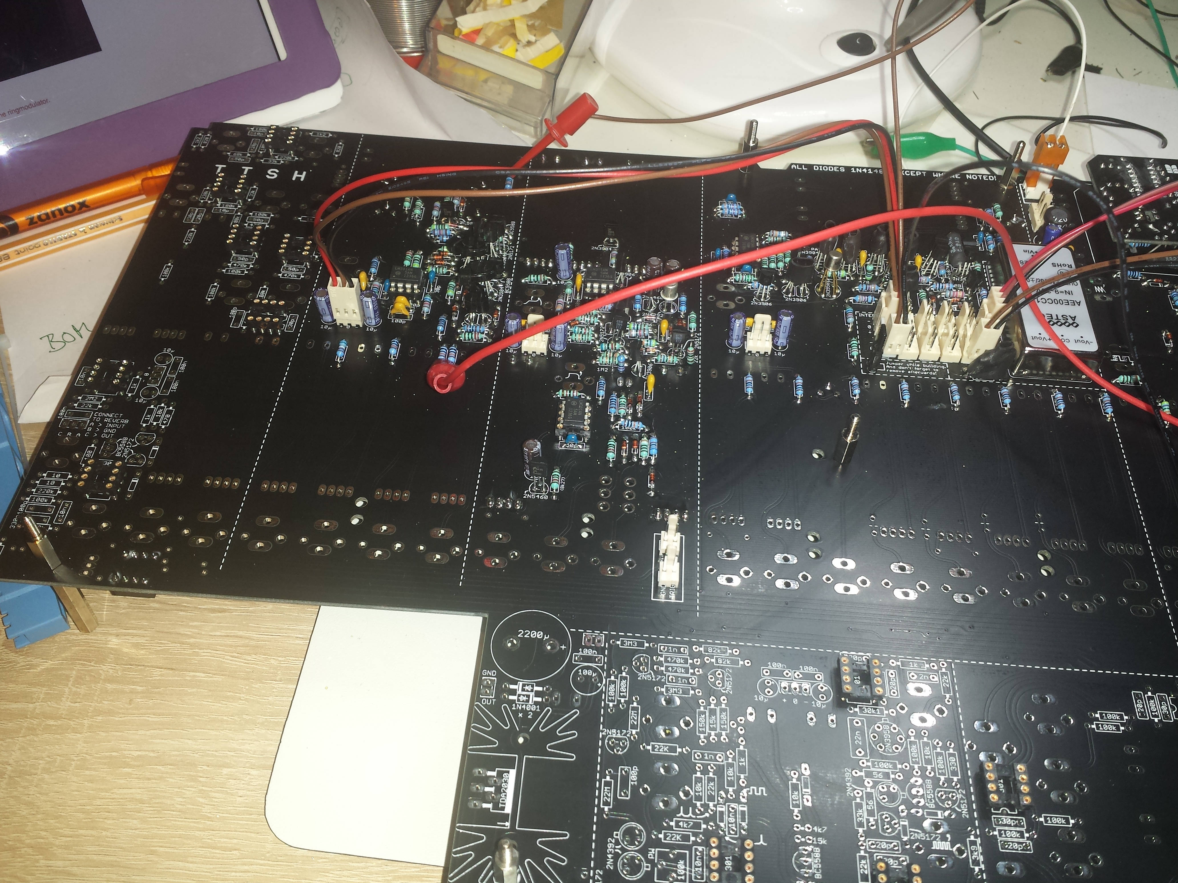
VCO testing - wiring a +15v cable to resistor and probe ..
see my solution..
further: dont solder the needed jack complete - solder only a bit, because the frontpanel don´t fit with this position 100%
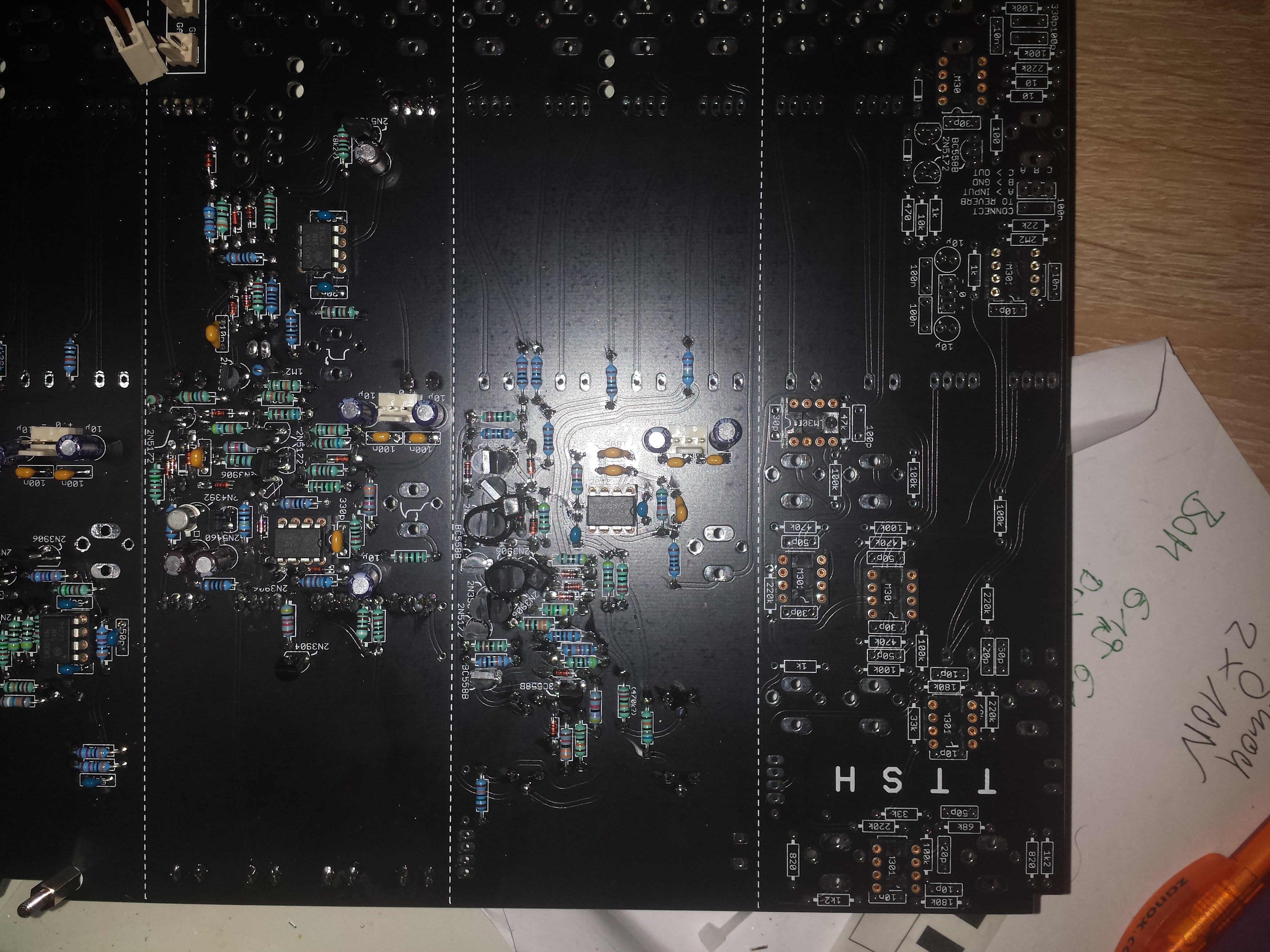
VCF picture - handle with care - 2n3904/06 - BC558 doublecheck the position near Tempco
further please read carefull zthees building guide for VCF - there is a issue with matched pair 2N3906 - silkscreen error etc.
AR/ADSR
VCA
for testing: test with probe a VCO (need +15V cable see VCO testing above)
feed the VCO signal to the VCA and check the waveform with a oscilloscope.

Ringmod, Preamp, Envelope Follower
Mixer
Don´t solder the parts complete - maybe the frontpanel dont match with this position..
Noise, Voltage Processor
with the 2n5172 the noise is distorted and have a very high gain..
tested Resolution:
leave out the 2n5172 - use a bc337, - bend right leg to top, solder a 10K resistor in series to the 10uF cap.

not shown here yet

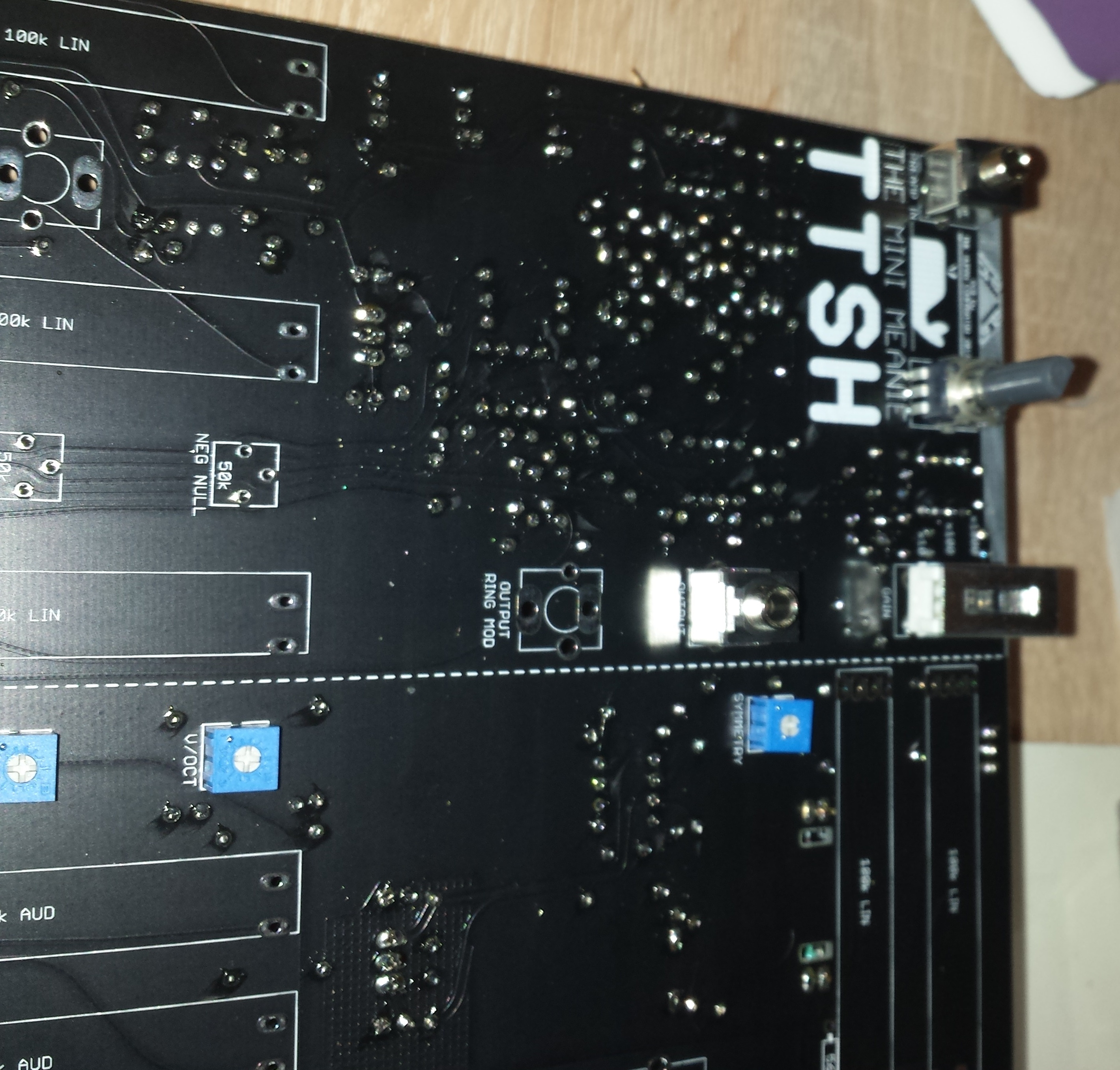
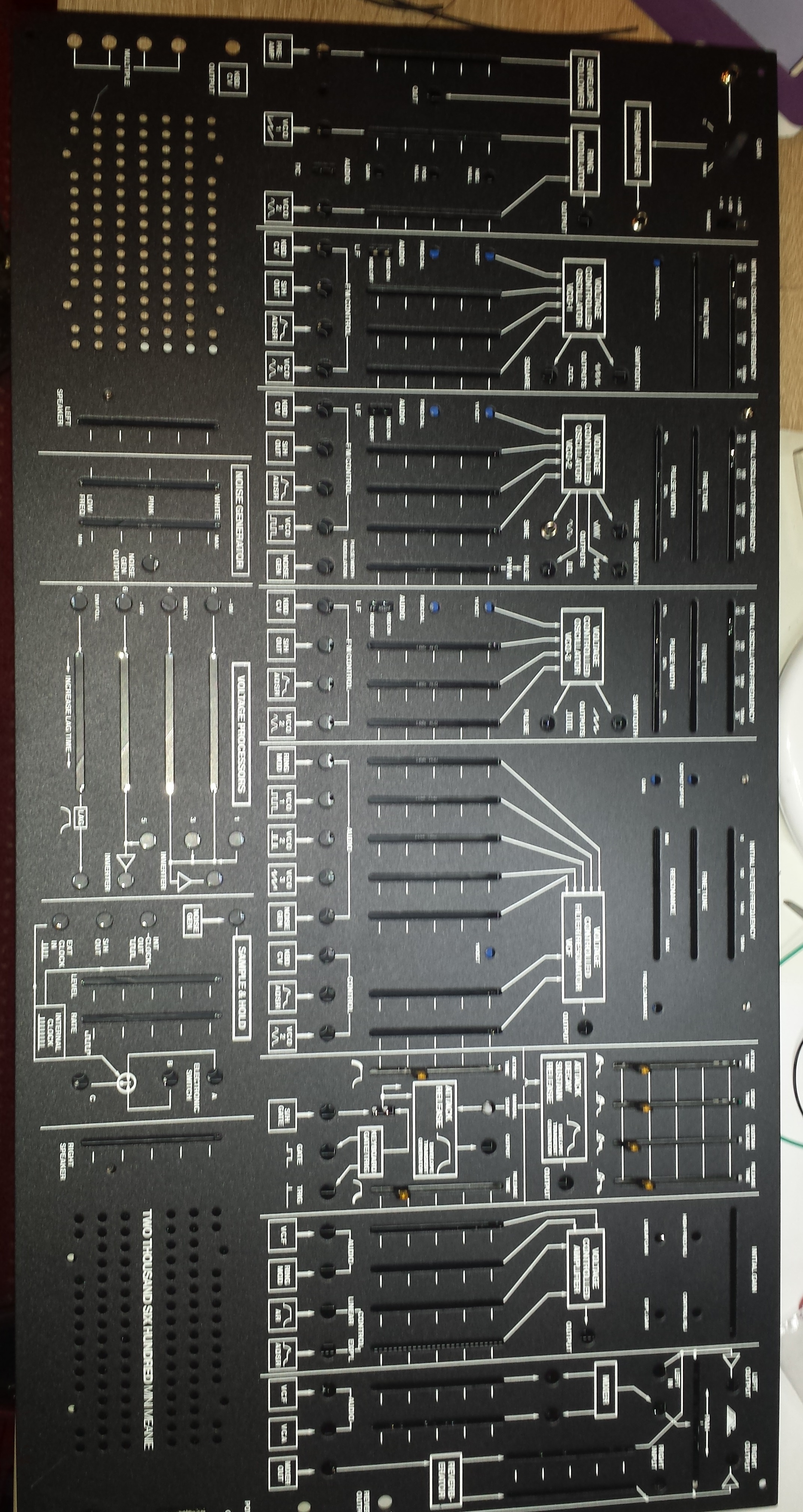
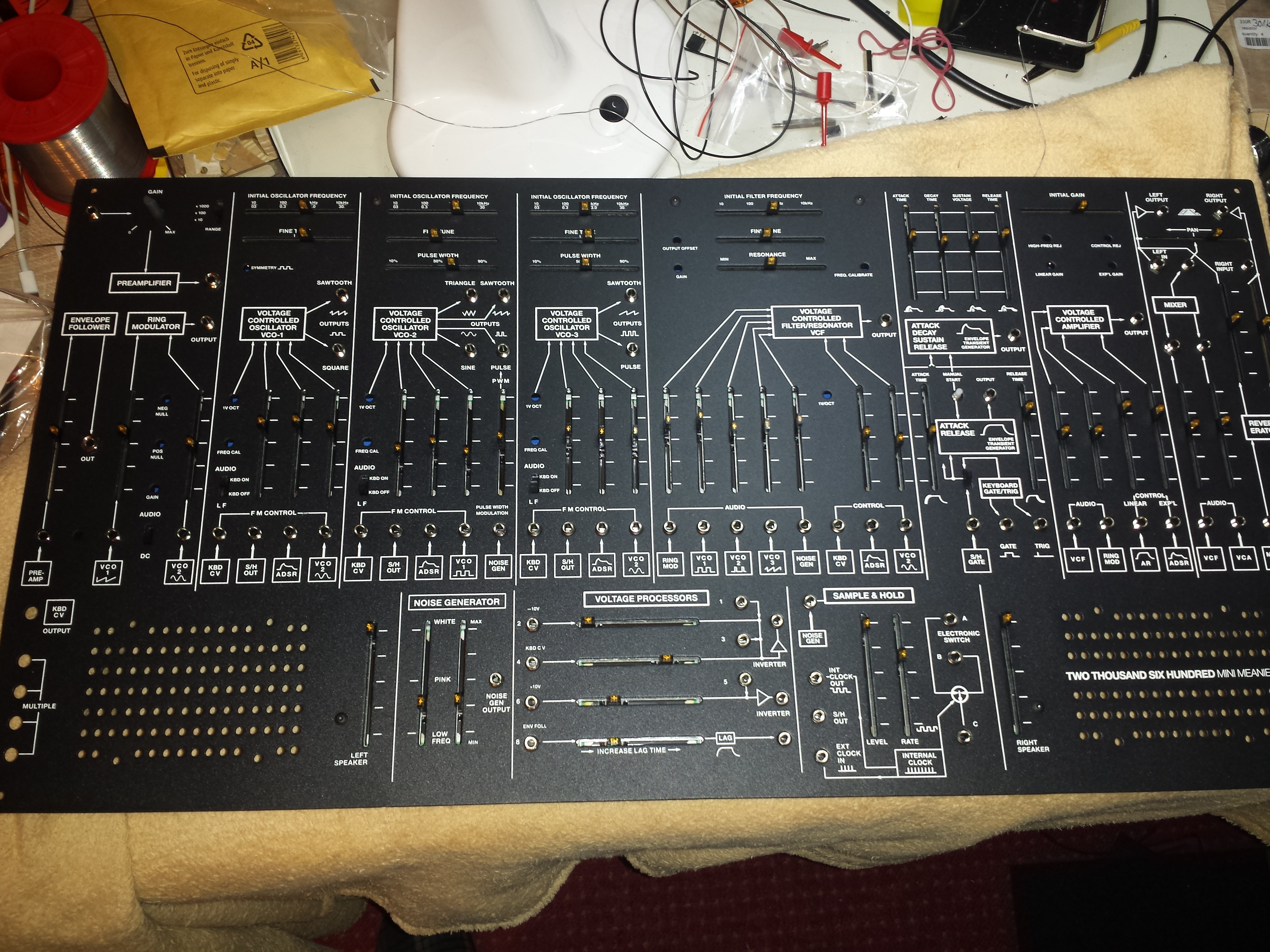
first Panel mounting test
S/H - Clock - Noise
addional Info: due to some issues from the clock LED driver - we bridge the 2n5172.
see here: http://thehumancomparator.net/modifications/
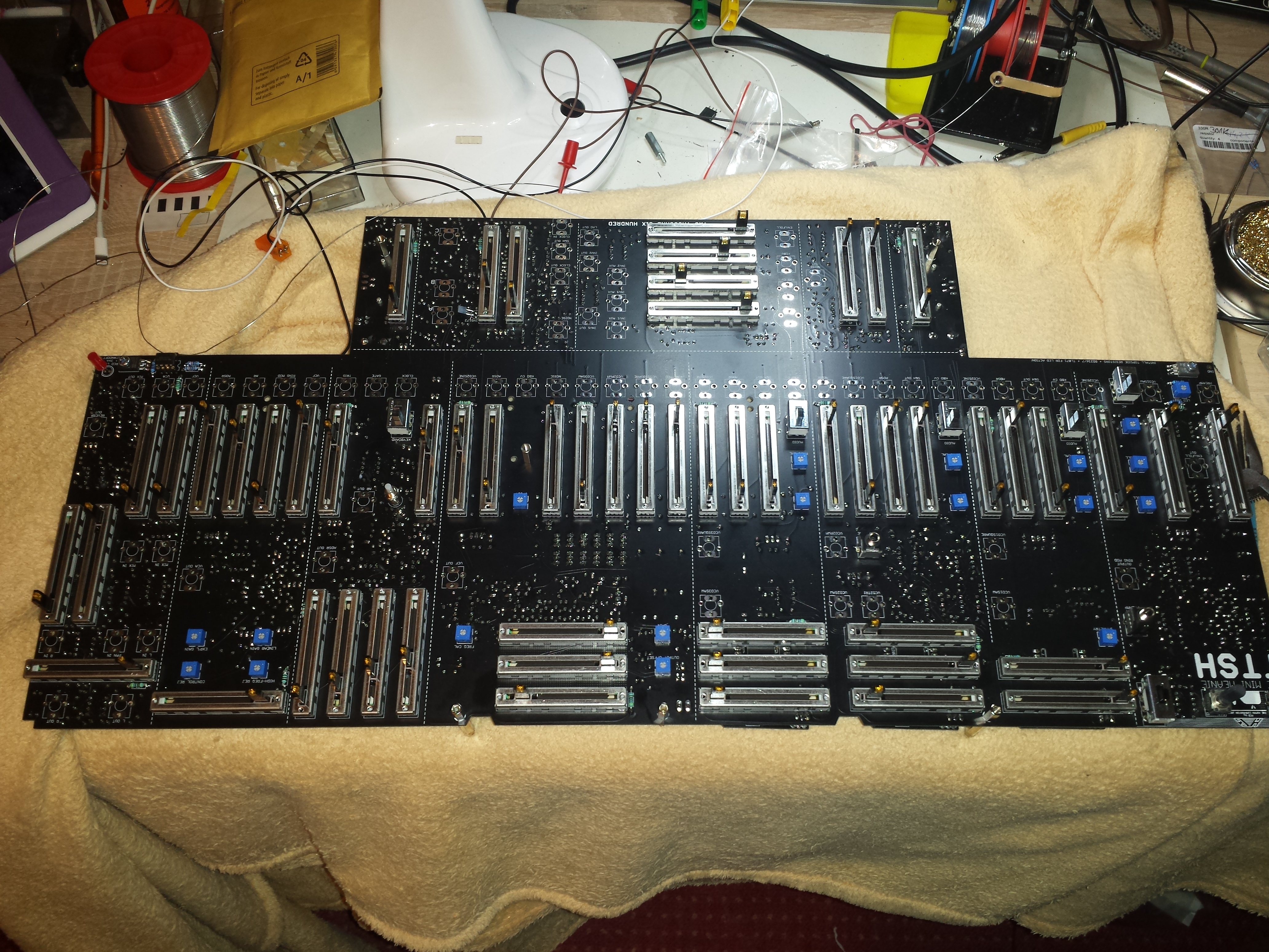
All Parts soldered, Panel mounted, need to solder the jacks.
Building tip:
place each row of faders on PCB and solder 2 pins, place the Panel in right way and mount all screws,-- solder the Faders complete.
remove the panel and plug all jacks in position, place the panel - mount all screws and few jacks with screws - turn the device, solder the jacks.
solder the LED at last.
Use on all sides spacers, for a faster panel un/mounting use spacers (with plastic/silicon washers) instead of screws and you can turn the panel on table without breaking some faders.

If you have trouble with noise leds, connect the 470r resistor near amp/noise to the unlabeled solder hole.

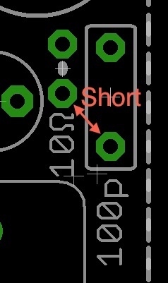
HUM Issue:
by using of both amplifiers for integrated speakers i had massiv hum, by touching the panel the hum sound changes. (hum is only in speakers not in main out)
a workarround from zthee, was tested by me - it helps.
Resolution:
short out the 10Ω resistor and the 100p capacitor in the PSU section. E.g. just make a small bridge between the pad close to 10Ω and 100p as in the attached picture.
finished:


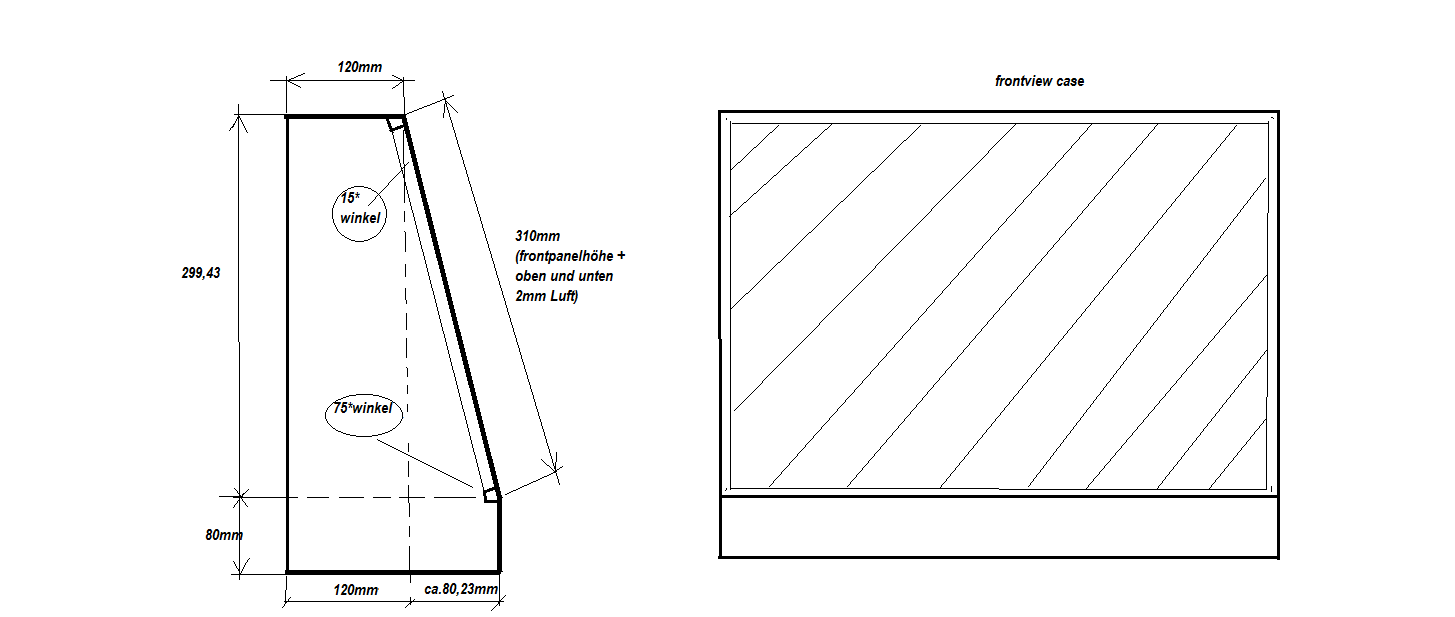
Planned Case: