Successful Build : 04/2019
tech:
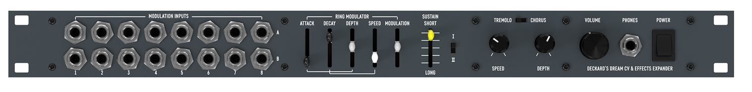
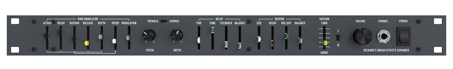
it adds an envelope controllable Ring Modulator, Chorus, Tremolo, Delay, and Reverb effects. It is designed to work seamlessly with Deckard’s Dream, but it also works as a standalone audio effects device.
Schematics:
DD-EXPANDER-SCHEMATICS-REV1.zip for rev.1.0
BOM:
DD-EXP-BOM-REV1.0.1.pdf latest version for rev.1.0 add 2x TL071 and 1x 4.7uF MLCC capacitor RM5
DD-EXP-BOM-REV1.0.0.xlsx (Old version) fore rev.1.0
rev.1.1 changes
the new PCB Version is 1.1 !! (midi noise fixed)
it use following changes which affect the above BOM, you have to respect this:
IC33 and IC37 is TL071 (DIP8)
C166 not in BOM 4.7uF ceramic (MLCC) RM5
DDRM Expander VC Placement Guide V2 from Kevin Looney:
DDRM Expander VC Placement Guide V2.pdf
DDRM FAQ and Build tipps from Todd
Deckard’s Dream Expander FAQ and Build Guide V1-7.docx
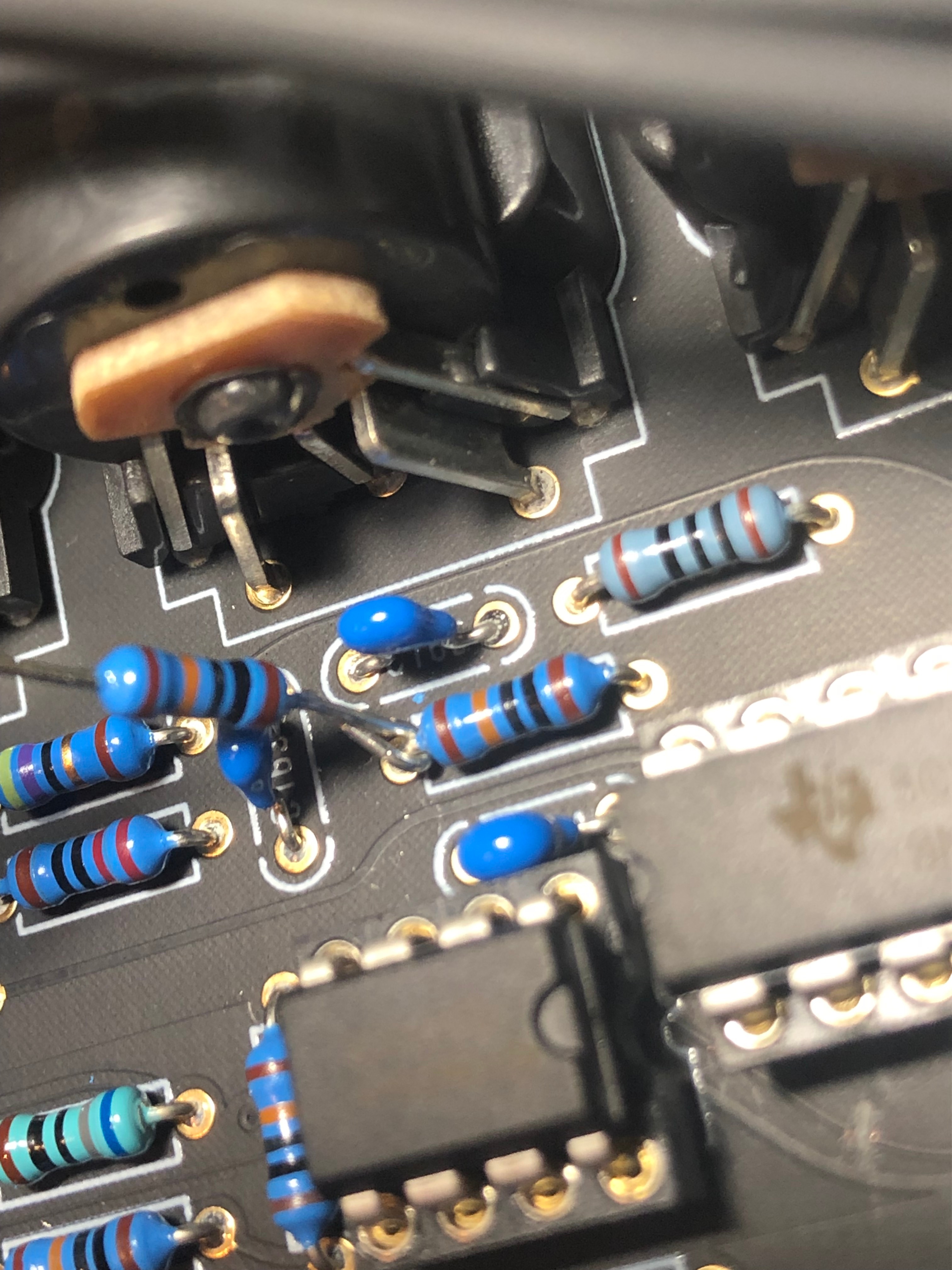
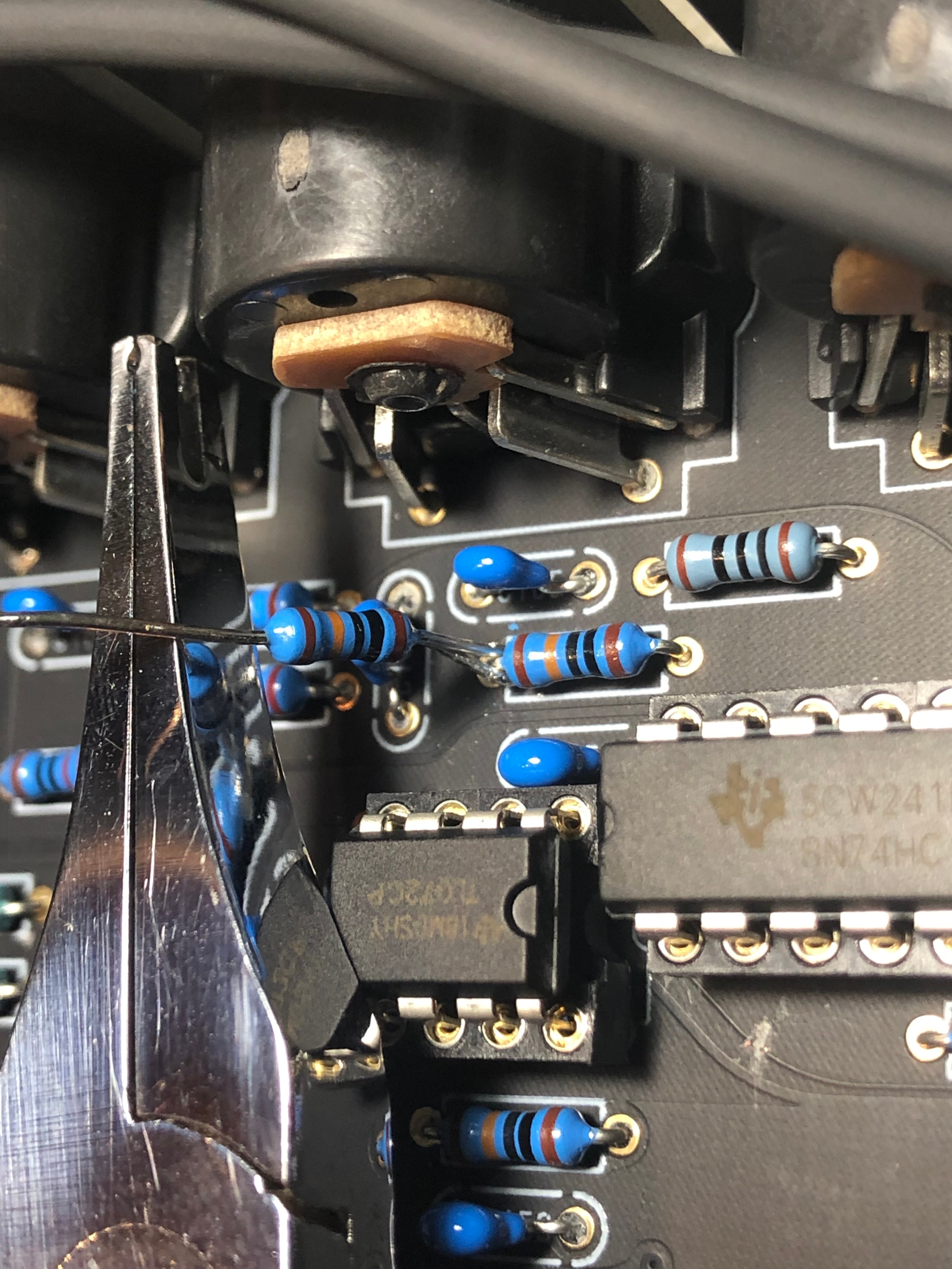
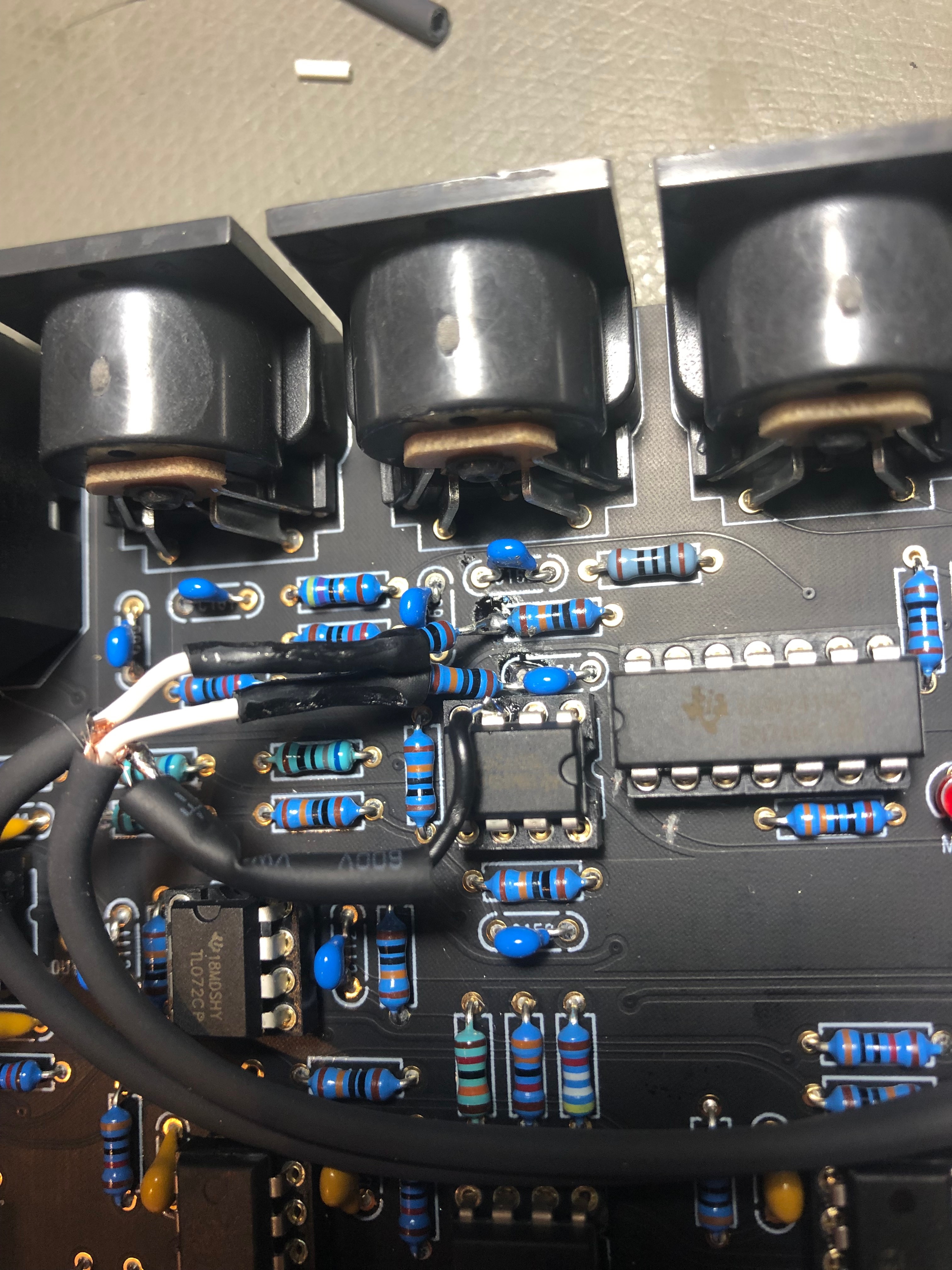
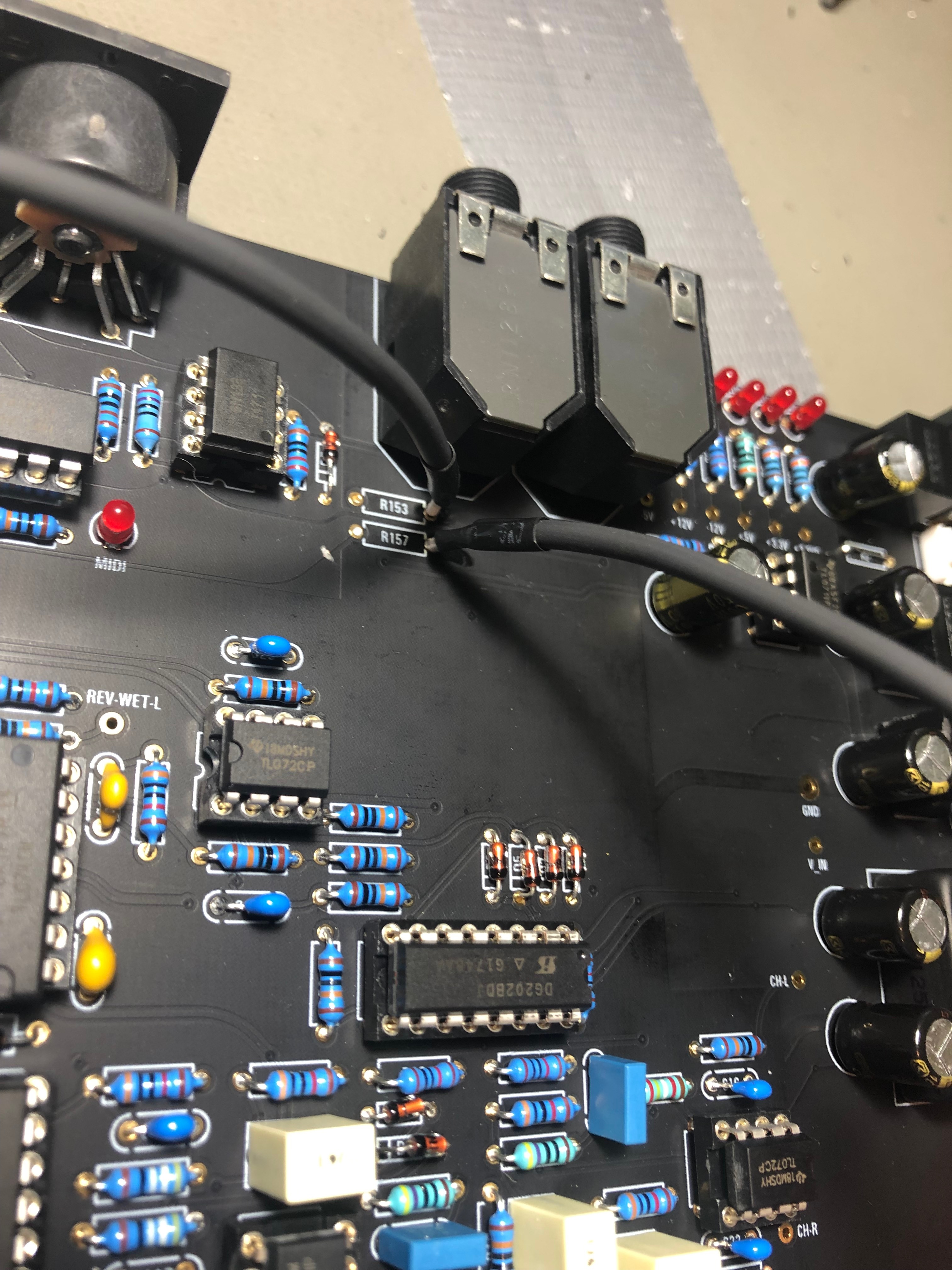
MIDI-NOISE FIX pictures:
only for DIY PCB Version 1.0
is fixed in DIY PCB Version 1.1
Pictures from rev1.0 pcb
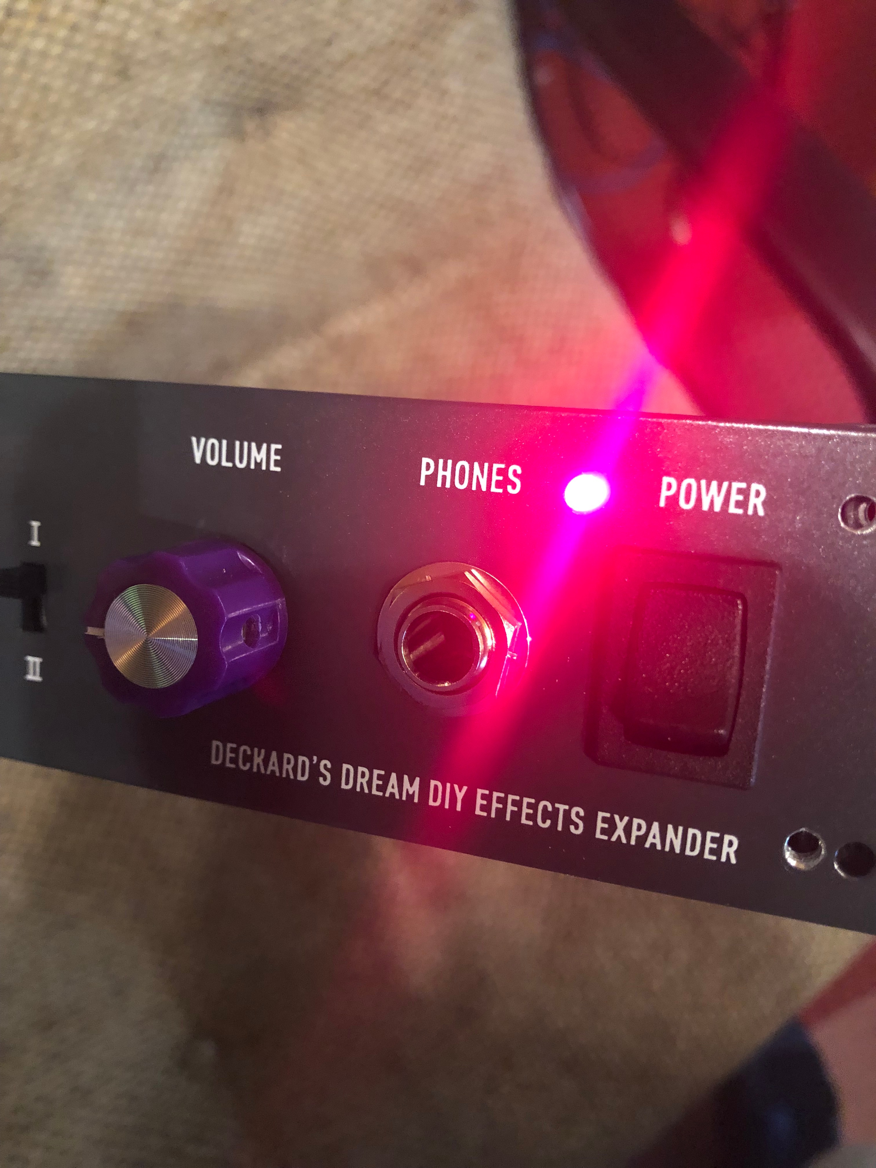
Power LED Installation:
remove the 12V LED from the Card PCB and drill a 4,5mm hole in the frontpanel - which is the standard size for 3mm LED-holders (available in most electronic shops)
psu DC-DC alternative part:
DKMW30F-12 meanwell (approval ![]() - tested
- tested ![]() )
)
The DSP chip, potentiometer, AS3310, As3340 from Musikding too ![]() confirmed
confirmed
Case: 169 USD
First Design Concept:
Final:
| There are no images attached to this page. |