Requirements:
good Solderstation
Soldercore 0,5mm & 1mm
BOM: (Bill of Material)
The PCB Set from DIYsynth.de contains:
1x ucb board (upper control board)
1x lcb board (lower control board)
1x Logicboard
2x Ferrite beads
24x 100nf RM2 polyester capacitors
Steps to your completed device:
important Info: the logicboard is mounted with the components thru the ucb and lcb boards - like this:
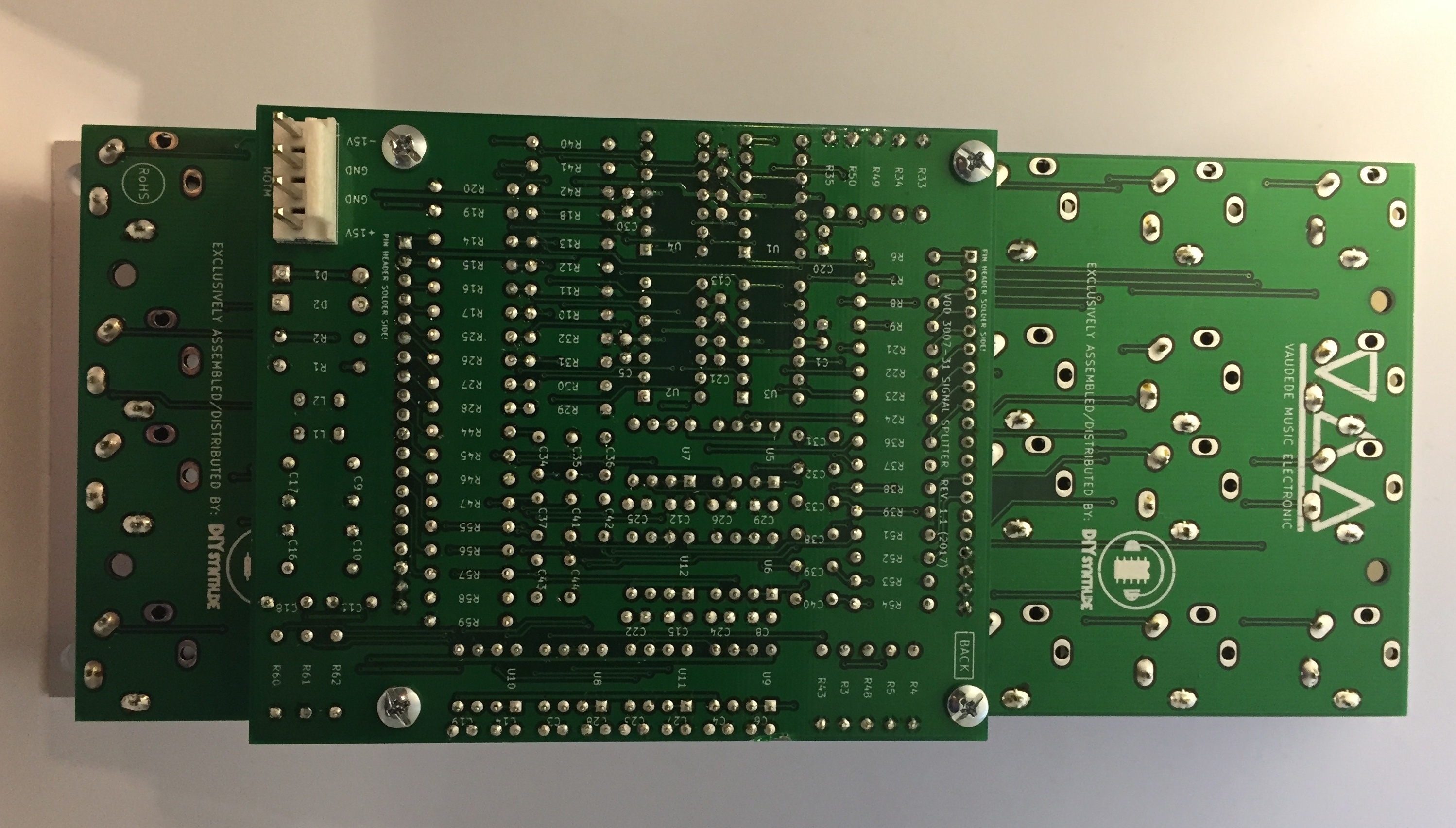
please read the guide before you start the build to understand my preferred guide, its possible to assemble the module in other ways too !
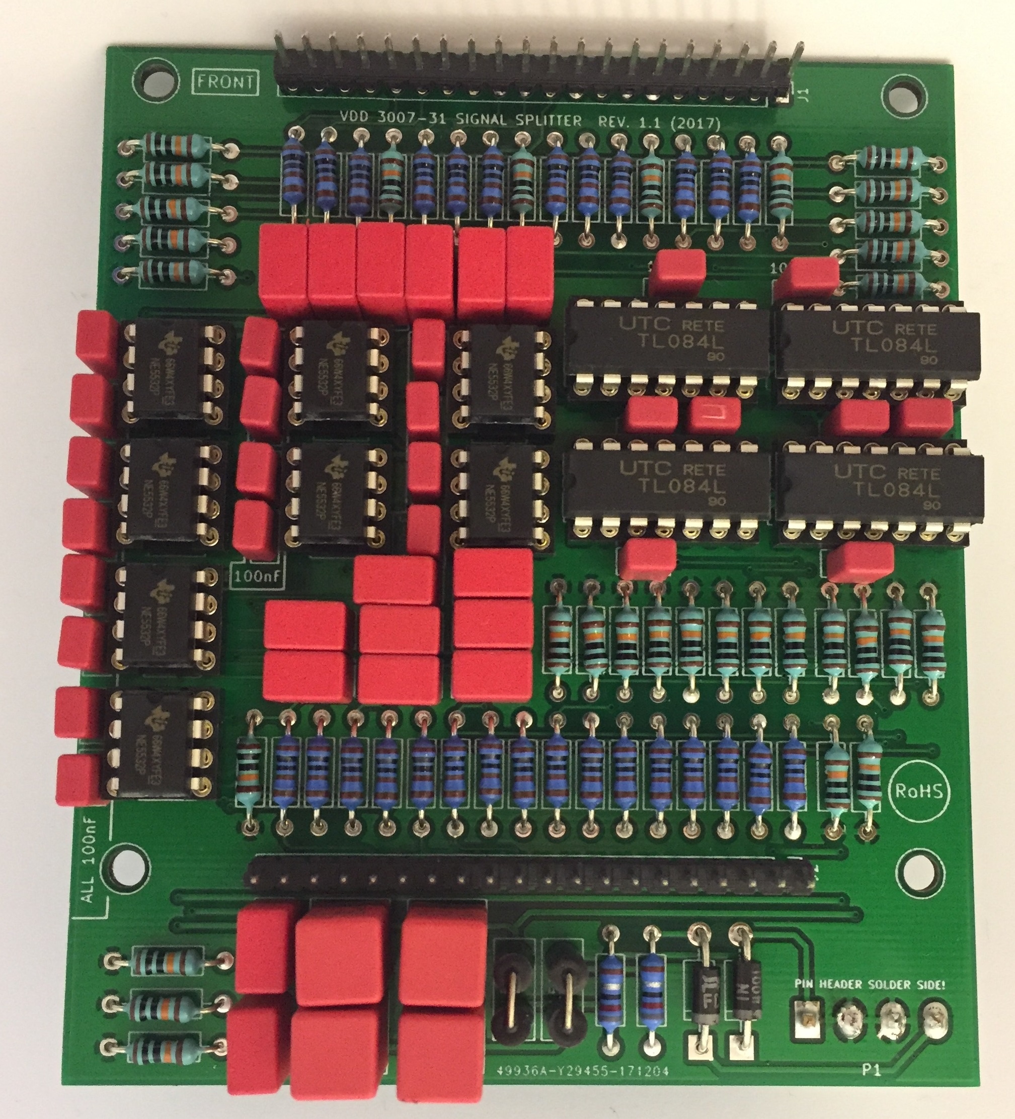
Logicboard
- start with the assembly of the Logicboard, don't attach both long headers !
- begin with the resistors you can solder from component side and turn the pcb - solder from solderside too.
- place and solder the rectifiers and ferrite beads
- place and solder the IC sockets (dont fit the ICs)
- place and solder the capacitors
- place the Power header (4pin MTA156) from solderside as shown here:
ucb & lcb PCB
- prepare the long headers: the distance between the controlbaord and logicboard must be 14-15mm, the big WIMA 4.7uF caps
the pinheaders are 7-8mm high, connect 2 together.
mount the male and female header together - the boards have a silkscreen layout for the 6,3mm jack - this is the component side !
- mount on the frontpanel with 4 jacks in each corner on one pcb, solder one pin on each jack, thats needed to have enough space to solder the pin headers like this:

4. attach the 4x 15mm spacers to the ucb and lcb
5. connect the male or female header to the ucb and lcb board
6. attach the logicboard on the headers
7. use screws or nuts (depends on orientation) on the 15mm spacers to get the pcbs in a stable and correct orientation
8. solder the logicboard headers
9. you only have 4 jacks on each pcb because we need the space to solder the haders directly between the frontpanel and ucb/lcb !
solder few pins on left, middle, rightside.
now you can remove the frontpanel and solder the other pins.
10. remove the logicboard, remove the ucb and lcb from frontpanel.
11. UCB: place the other jacks and move carefully the frontpanel from top on the ucb, attach the washer and nuts to the 4 soldered jacks
12. LCB same as 11.
next steps depends on your personal DIY experience
13. attach the logicboard to the ucb and lcb, test with a rectifier for shorts between -15v/GND/15V and measure under voltage at the IC sockets the voltage
14. if 13. is ok - add all ICS and test the module
testing process Active Splitter
Connect a Audiosignal to the Active Splitter IN A
this signal can be found now on left Out row and second Out row.
connect a audiosignal to the active splitter IN B
this signal can be found now second Out row.
testing process buffered multiple:
Connect a CV signal to the Buffered multiple IN A
this signal can be found now on left Out row and second Out row.
connect a CV signal to the Buffered multiple IN B
this signal can be found now second Out row.