what you need:
the Midi device/pcb assembled 50€ plus shipping
http://www.midi-hardware.com/index.php?section=prod_info&product=MIDimplant
1x special gatebooster: around 10€
https://oshpark.com/shared_projects/mYFtCAXo
(ask me, i can organize it)
some pcb headers male/female
Midi connector
cables for wiring around 3m in total (with gatebooster)
see gatebooster mod for
Build guide:
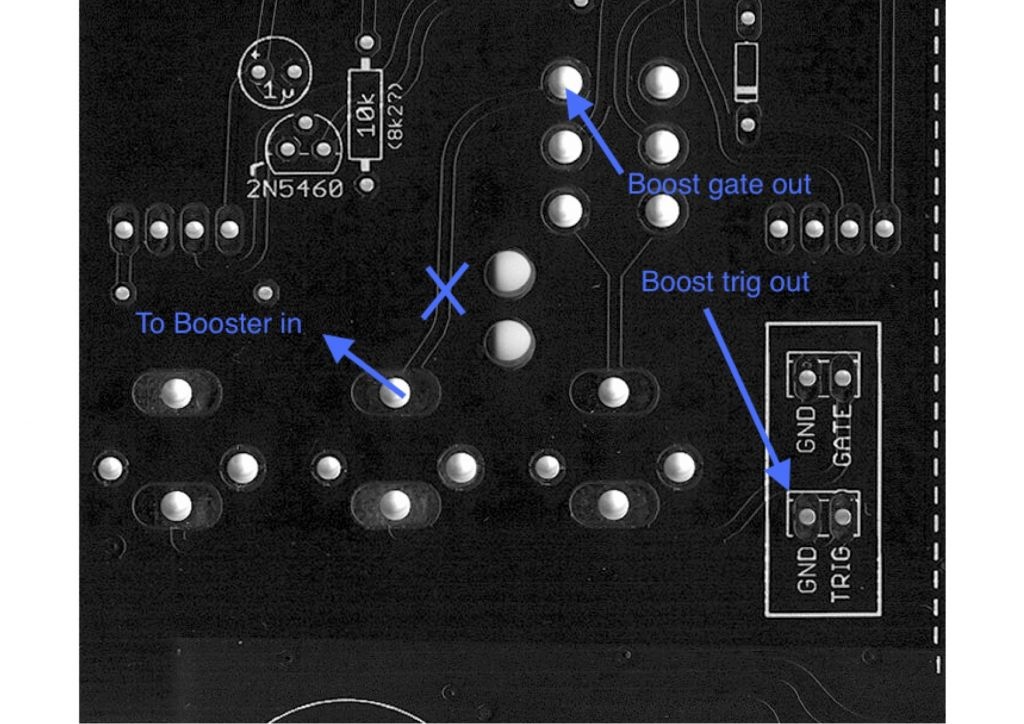
1.assemble all parts on the gatebooster, except the headers.
2.solder like shown in my pictures some headers for midiimplant on the gatebooster pcb, i prefer a adapter with male/female headers to remove the midi pcb from gatebooster (for repairs or testing)
3. do the wiring job for the midi connector - mount it in the case - then solder the cables (or you run later in trouble when you try to build in the midi connector in the case - the connector must be built in from front.)
pin 3 and 5 of the midi jack is the signal what you have to connect with the 3 pol header (from left pin 1 and 2 ) on the gatebooster pcb, the third pin is for gate input from ttsh.
4. run a wire from CV1 to the TTSH mainboard pcb header EXT CV IN (no ground needed here)
5. run 3 cables to the GATE/S-H switch section, use the gate/trigger/Gate input from the gatebooster, not to the midiimplant pcb !
6. for testing/learn function add a pushbutton to midiimplant - wire the pushbutton between ground an LEARN (LRN)
7. power wiring.. on the ttsh mainboard are on each section 6 pcb "holes" this is power, check with a voltmeter for -15v/GND/15v and run cables to the gatebooster power input (near the 10uf electrolyt caps)
DONT run the powerwiring to midiimplant header.
8. testing .. more later here..
Gallery:
| There are no images attached to this page. |