...
use for the wiring from top to bottom pcb:
8x from mouser:
FST-21A-8
TE Connectivity FFC / FPC Jumper Cables
TARIC:8544499500 ECCN:EAR99 COO:MX
BOM note:
the most important things are:
| PIC chip | preprogrammed with bootlader | ask me if you want one preprogrammed PIC chip | |
| SID chips | 2x needed - one minimum 8580 or 6581 or 6582 | ebay or ask me | |
| Frontpanel and rearpanel | http://thebeast.co.uk/?product_cat=midibox schaeffer | ||
| original power supply (latest square box version) | ebay | ||
| powerswitch from ebay- or use a DPDT switch on rearpanel | |||
| Powersupply DIN Jack | |||
| low current LED´s - which fit against the front panel hole | make sure the color match with the display | tme, mouser | |
| Display HD44780 | make sure the color match with the LEDs | ebay or | |
| case Pactec PT10 | mouser | ||
| FAN only when you install 6 or 8 SIDs | 5Volt 40mm fan - ebay | ||
| 9x flat ribbon cable to connect the pcbs together | FST-21A-8 | ||
DO NOT INSTALL ALL headers and IC sockets or output drivers if you only want 2 SID chips - you have to install and buy less parts | you only need 2 SID chips and one preprogramed PIC chip. more SIDs. can be played on a different MIDI channel - but there's no real Polyphonic playing on one midi channel. (correct me if I´m wrong) |
Build Infos (mostly for myself)
Control surface build:
http://www.midibox.org/dokuwiki/doku.php?id=wilba_mb_6582
Base PCB build:
http://www.midibox.org/dokuwiki/doku.php?id=wilba_mb_6582_base_pcb_construction_guide
Display:
http://midibox.org/forums/topic/14564-building-the-mb-6582-control-surface-photo-tutorial/
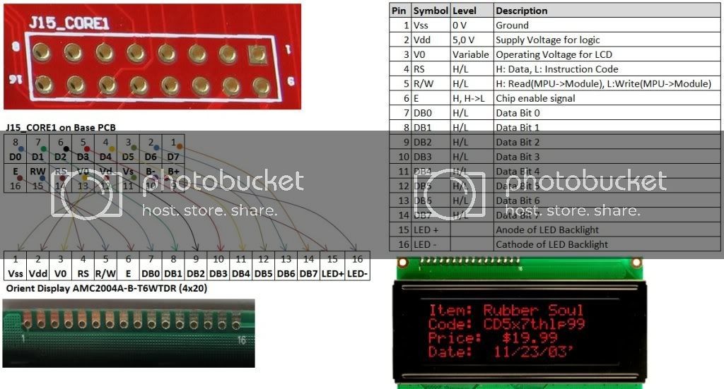
I used the 2004A model: (HD44780)
Pinout
| number_marked_on_Display | ||||||||||||||||
|---|---|---|---|---|---|---|---|---|---|---|---|---|---|---|---|---|
| Display PIN | 1 | 2 | 3 | 4 | 5 | 6 | 7 | 8 | 9 | 10 | 11 | 12 | 13 | 14 | 15 | 16 |
| Display Function | VSS | VDD | V0 | RS | R/W | E | DB0 | DB1 | DB2 | DB3 | DB4 | DB5 | DB6 | DB7 | BLA(+) LED + | BLK(-) LED - |
| on Mainboard: | 11 | 12 | 13 | 14 | 15 | 16 | 8 | 7 | 6 | 5 | 4 | 3 | 2 | 1 | 9 | 10 |
| check |
Mainboard:
| 1 | 2 | 3 | 4 | 5 | 6 | 7 | 8 | 9 | 10 | 11 | 12 | 13 | 14 | 15 | 16 |
|---|---|---|---|---|---|---|---|---|---|---|---|---|---|---|---|
| D7 | D6 | D5 | D4 | D3 | D2 | D1 | D0 | B+ | B- | VSS | VDD | V0 | RS | RW | E |
User Manual:
http://www.ucapps.de/midibox_sid_manual_fp.html
...
http://midibox.org/forums/topic/18680-solved-debugging-my-mb-6582-part-2-software-upload-issue/
Build infos for myself:
...
Todos after build:
http://www.midibox.org/dokuwiki/doku.php?id=wilba_mb_6582
Base PCB build:
http://www.midibox.org/dokuwiki/doku.php?id=wilba_mb_6582_base_pcb_construction_guide
Display:
http://midibox.org/forums/topic/14564-building-the-mb-6582-control-surface-photo-tutorial/
I used the 2004A model:
Pinout
...
BLA(+)
LED +
...
BLK(-)
LED -
...
16
...
after programming:
fit LED resistors R40-R55 - start with one and check the brightness - some colors need 1K or more. they are connect in a chain - but in the Matrix is often only one LED at one time powered - its different with the other LEDs !! so it can happen that the LED matrix LED´s needs a other resistor value.
Mainboard:
...
after programming:
LED resistors R40-R55 (220R)
...
What's the purpose of the J70 header?
...