DB
| Panel | ||||||||||
|---|---|---|---|---|---|---|---|---|---|---|
| ||||||||||
Projecttitel:MB6582Status:
Startdate: 08/2019Duedate: 05/2020Manufacture link:uncapsucapps.de |
| Table of Contents | ||||
|---|---|---|---|---|
|
...
wilba_mb_6582_parts_list [MIDIbox].pdf
use for the wiring from top to bottom pcb:
8x from mouser:
...
BOM note:
the most important things are:
| PIC chip | preprogrammed with bootlader | ask me if you want one preprogrammed PIC chip | |
| SID chips | 2x needed - one minimum 8580 or 6581 or 6582 | ebay or ask me | |
| Frontpanel and rearpanel |
| see note for the ID:output in this list to improve the rear panel | http://thebeast.co.uk/?product_cat=midibox schaeffer - see extra notes after this list | ||
| original power supply (latest square box version) | ebay or better this new stable version: https://www.c64psu.com/c64psu/43-commodore-64-c64-psu-power-supply.html | ||
| powerswitch from ebay- or use a DPDT switch on rearpanel | |||
| Powersupply DIN Jack | |||
| low current LED´s - which fit against the front panel hole | make sure the color match with the display | tme, mouser | |
| Display HD44780 | make sure the color match with the LEDs | ebay or | |
| case Pactec PT10 | mouser | ||
| FAN only when you install 6 or 8 SIDs | 5Volt 40mm fan - ebay | ||
| 9x flat ribbon cable to connect the pcbs together | FST-21A-8 | ||
DO NOT INSTALL ALL headers and IC sockets or output drivers if you only want 2 SID chips - you have to install and buy less parts | you only need 2 SID chips and one preprogramed PIC chip. more SIDs. can be played on a different MIDI channel - but there's no real Polyphonic playing on one midi channel. (correct me if I´m wrong) |
...
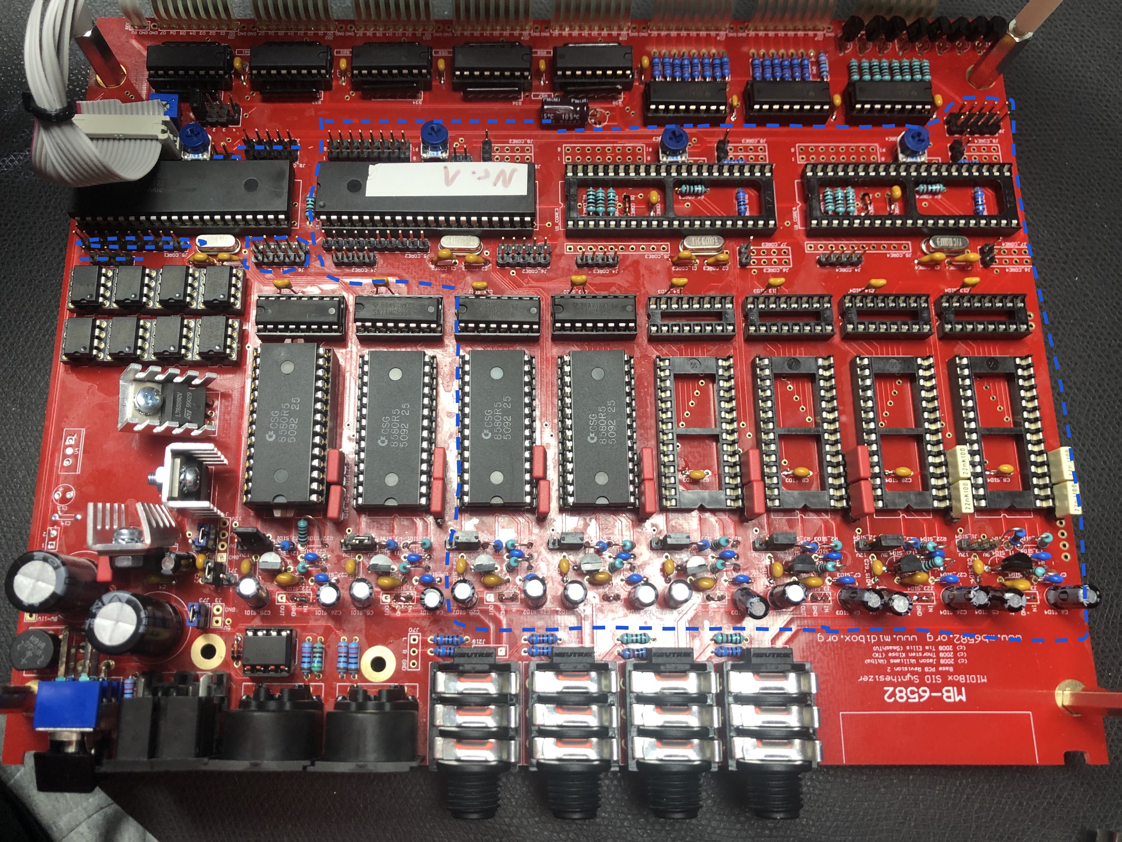
everything inside the blue marking isn't needed when you only want a 2 SID chip version. also the headers which are blue marked.
| |||
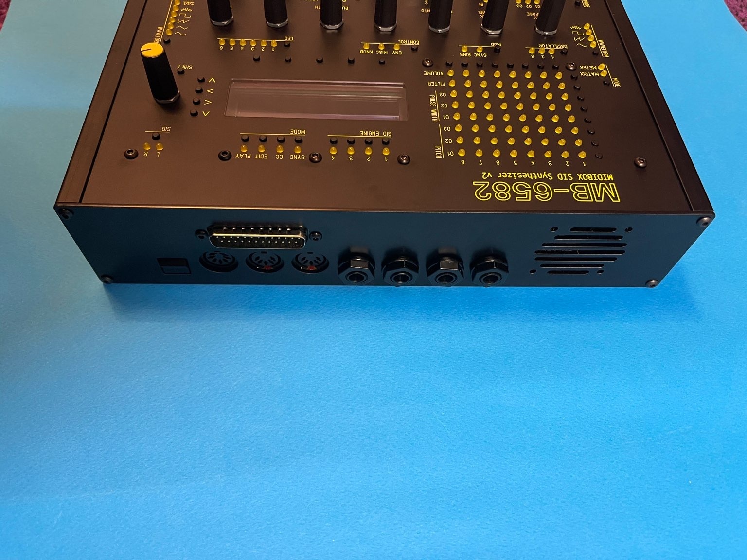
| ID:output | ABSOLUTLY important | the outputs are Stereo per jack !! if you only install 2 SIDs - you can improve the jacks - install 2 MONO Jacks at the rear panel and connect each on the (Voice 1) stereo solder holes - other wise you need a adapter from stereo to 2x mono cables (insert cable) | todo: improve the rear panel to 2 or 4 MONO jacks (9.5mm holes) move the holes more to top to get enough space between PCb and the jacks. remove the unused holes from the panel files |
Panel Files:
This one has all artwork as objects in FPD, with two HPGL engravings for the Osc and LFO waveforms. You can change individual text labels if you want:
This one is the same as the one above, but pen 1 is used for all text, control group lines and waveform lines, i.e. - 1=text & control group lines & waveform lines, 2=arrow labels, 3=section dividing lines. You can then change the colour and/or thickness of each type of artwork.
This one has all artwork as a single HPGL engraving object
Build Infos (mostly for myself)
Buildguide of Control panel
http://midibox.org/forums/topic/14564-building-the-mb-6582-control-surface-photo-tutorial/
Control surface build:
http://www.midibox.org/dokuwiki/doku.php?id=wilba_mb_6582
...
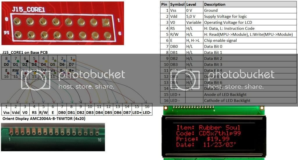
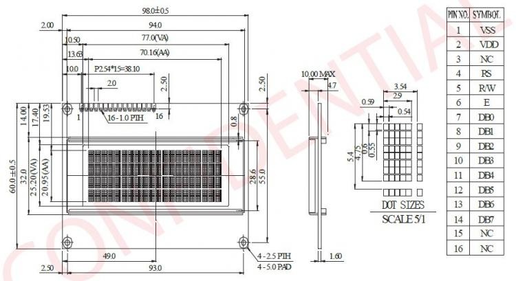
I used the 2004A model: (HD44780)
Pinout
| number_marked_on_Display | ||||||||||||||||
|---|---|---|---|---|---|---|---|---|---|---|---|---|---|---|---|---|
| Display PIN | 1 | 2 | 3 | 4 | 5 | 6 | 7 | 8 | 9 | 10 | 11 | 12 | 13 | 14 | 15 | 16 |
| Display Function | VSS | VDD | V0 | RS | R/W | E | DB0 | DB1 | DB2 | DB3 | DB4 | DB5 | DB6 | DB7 | BLA(+) LED + | BLK(-) LED - |
| on Mainboard: | 11 | 12 | 13 | 14 | 15 | 16 | 8 | 7 | 6 | 5 | 4 | 3 | 2 | 1 | 9 | 10 |
| check |
Mainboard:
| 1 | 2 | 3 | 4 | 5 | 6 | 7 | 8 | 9 | 10 | 11 | 12 | 13 | 14 | 15 | 16 |
|---|---|---|---|---|---|---|---|---|---|---|---|---|---|---|---|
| D7 | D6 | D5 | D4 | D3 | D2 | D1 | D0 | B+ |
| B- | VSS | VDD | V0 | RS | RW | E |
for OLED VERSIONS:
use the wiring as shown on bottom - you don't need all Pins connected (on LCDs you have to connect all pins as shown above)
bridge on the Mainboard the pins
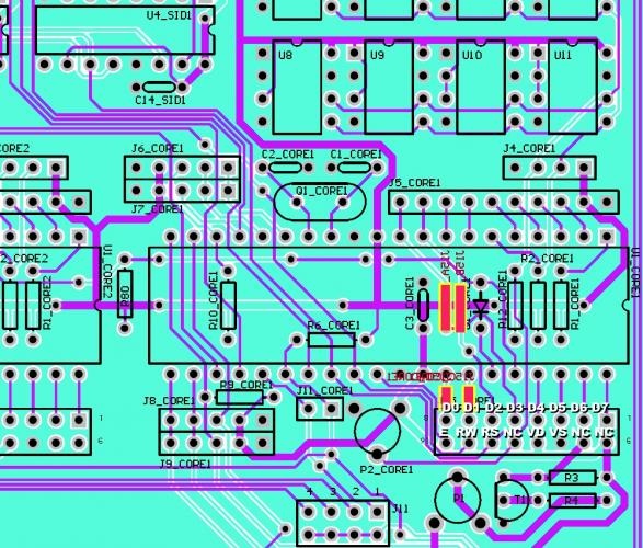
You have to solder the 4 small SMD Jumper bridges on the bottom on the MainboardPCB (only for OLED version)
User Manual:
http://www.ucapps.de/midibox_sid_manual_fp.html
...
http://www.ankman.de/commodore-64-sid-music/#a1998