...
BOM: (or order an assembled Version from diysynth.de)
| Amount | Part | Source | Mouser | tme.eu |
|---|---|---|---|---|
| 1 | pcb | diysynth.de | ||
| 1 | LT1054 SOIC 8 | check the datasheets for voltage operation ! the input voltage is from your wandwart powersupply like 9-12V DC https://www.mouser.de/ProductDetail/Analog-Devices-Linear-Technology/ |
LT1054CS8-SMD | ||||
| 1 | LM7908 | https://www.mouser.de/ProductDetail/ON-Semiconductor-Fairchild/LM7908CT?qs=%2fha2pyFadujt3%2f9kcI1ojRvjBqETND0G1EFAI2FtFq8%3d | https://www.tme.eu/de/details/lm7908ct/ungeregelte-spannungsstabilisatoren/on-semiconductor-fairchild/ | |
| 2 | 10uF tantal capacitor | 293D106X9025D2TE3 | ||
| 1 | 10pf capacitor SMT 0805 0603 | https://www.mouser.co.uk/ProductDetail/Wurth-Electronics/885012008019?qs=sGAEpiMZZMs0AnBnWHyRQEGbLOF2VP1iqcmVcmnwX7UxaJ2jp2TLLg%3d%3d | CL21C100JBANNNC | |
| 1 | 5mm metal spacer or a long M3 screw with washer and 2-3 M3 nuts | TFM-M3/5 plus 3mm washer and nut |
Build guide
INFO: I´m not responsible for your work or result, you need SMT soldering skills
PCB Assembly:
| Warning |
|---|
make sure your LT1054 is this version (LT1054CS): and not the "LT1054L" version. |
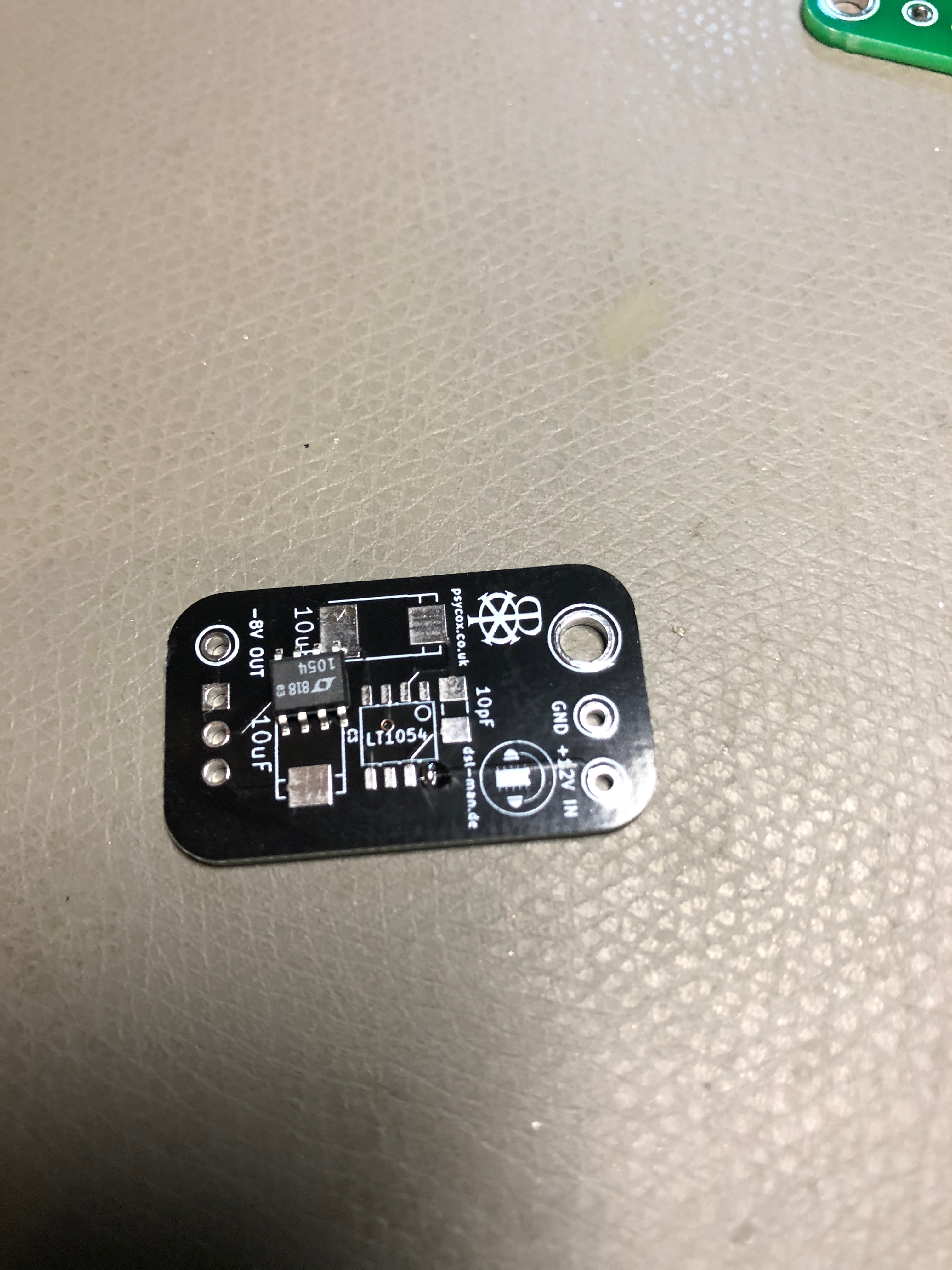
- solder the LT1054 on the pcb, double check the pinout !! for my LT1054 (from TME.eu) is the pinout as shown on bottom pictures, i haven´t checked the mouser version pinout.
i prefer to add a bit of soldercore on one pad, this gives you a easier placement of the IC.
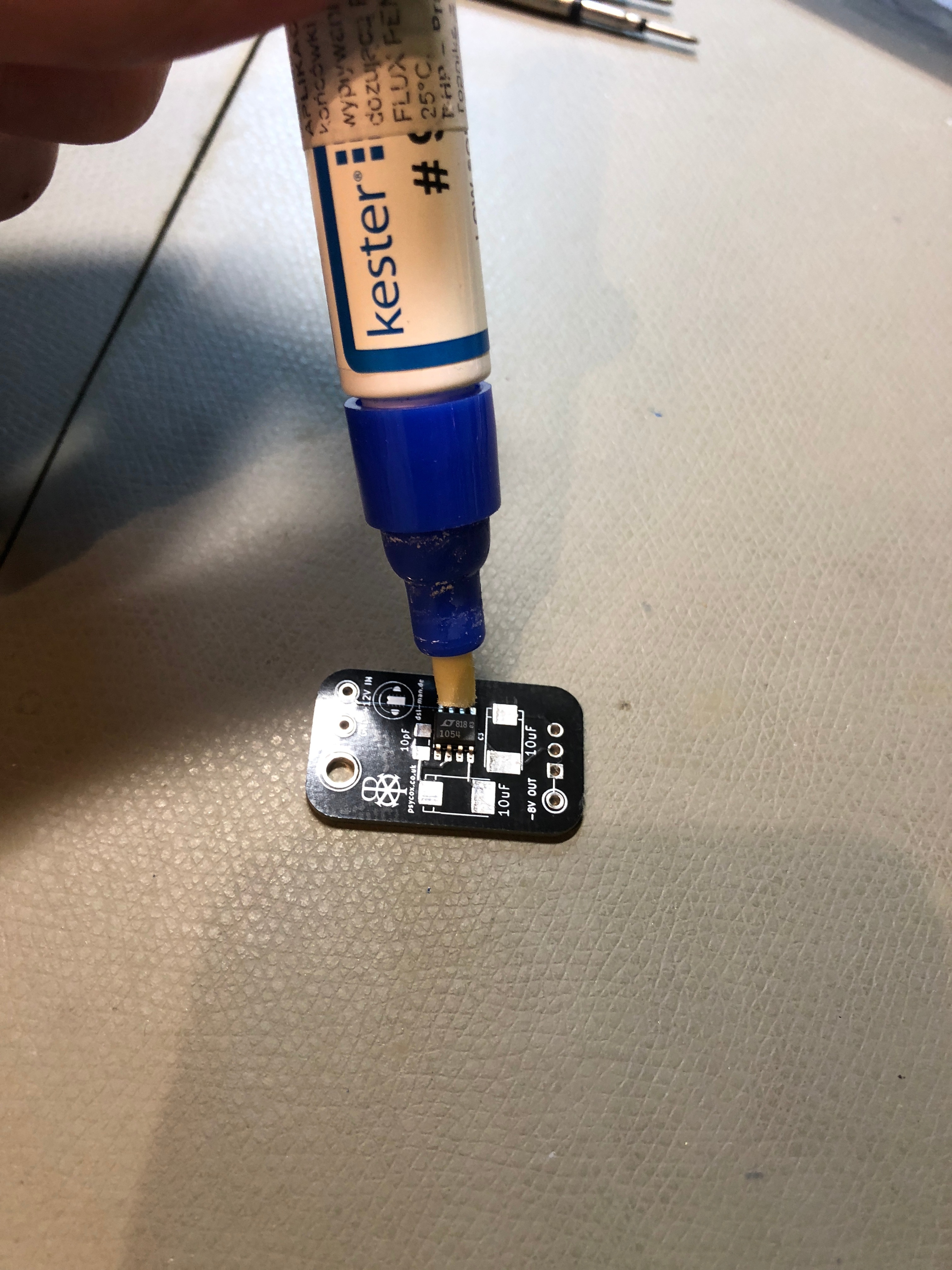
for the other pads use a kester flux pen for a better and easier soldering.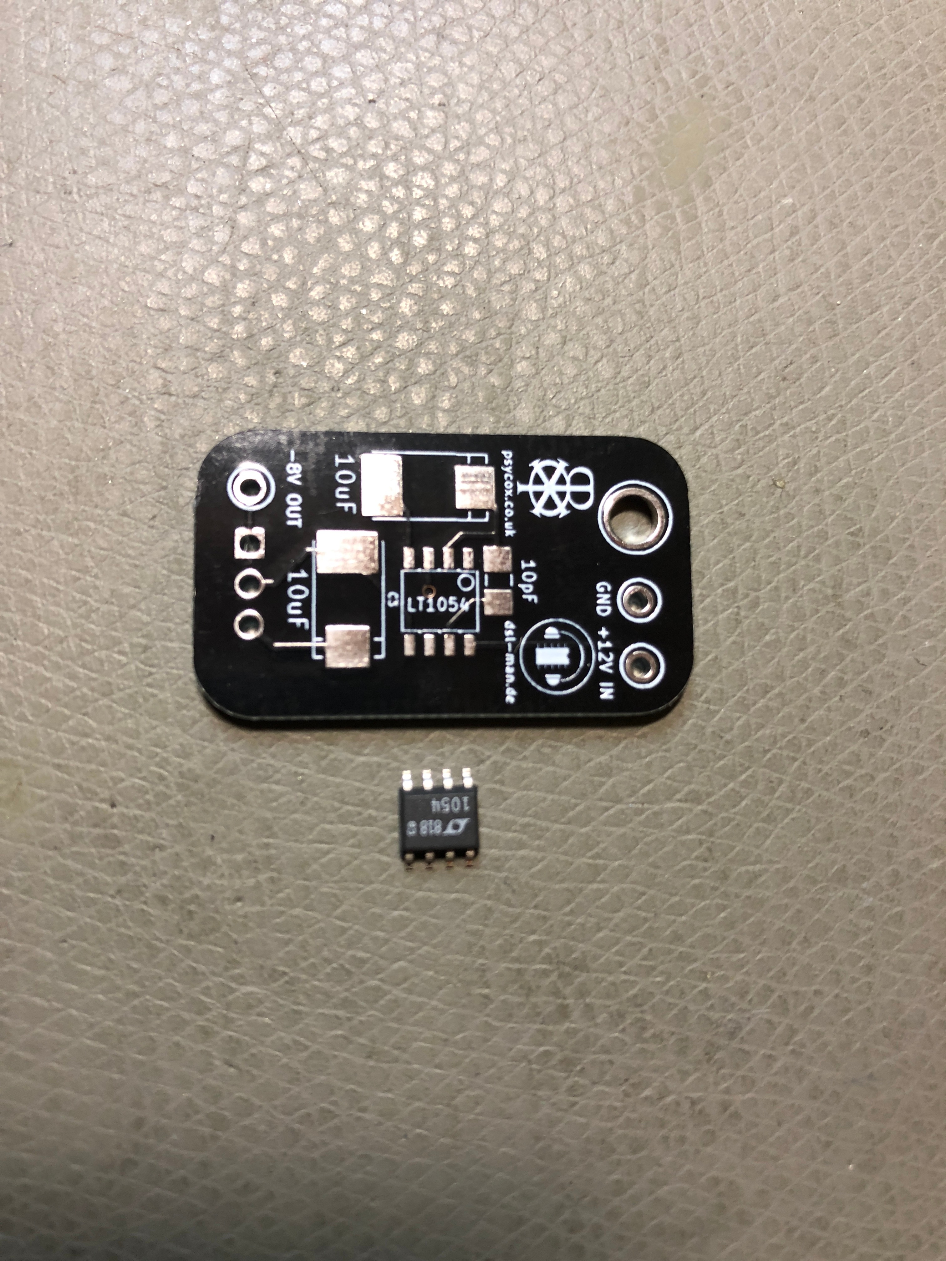
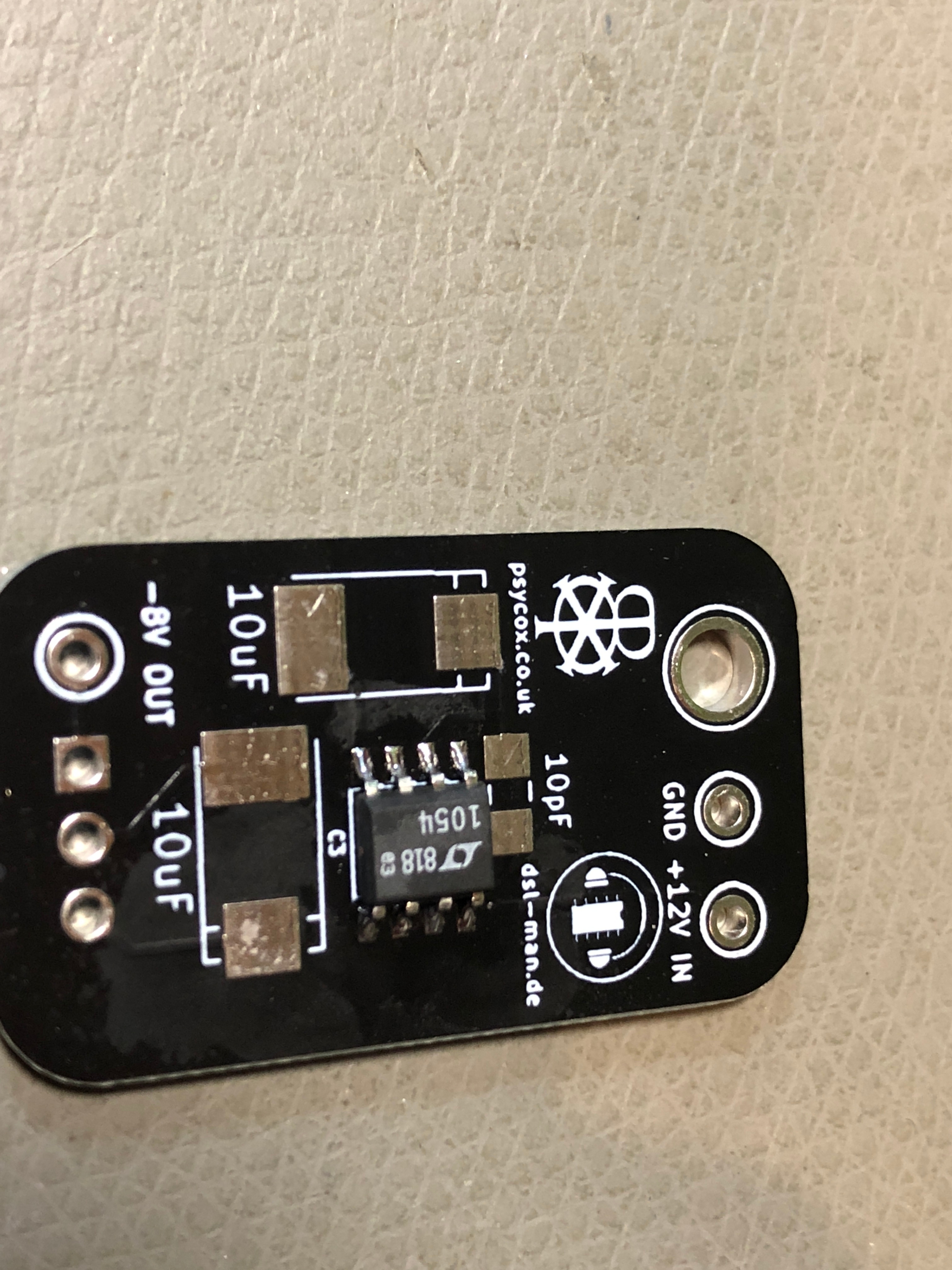
- solder the tantal capacitors
apply on one pad on each tantal capacitor pad, solder core.
place the part on in correct orientation on the pads (see bottom picture in case you dont know which polarity is used)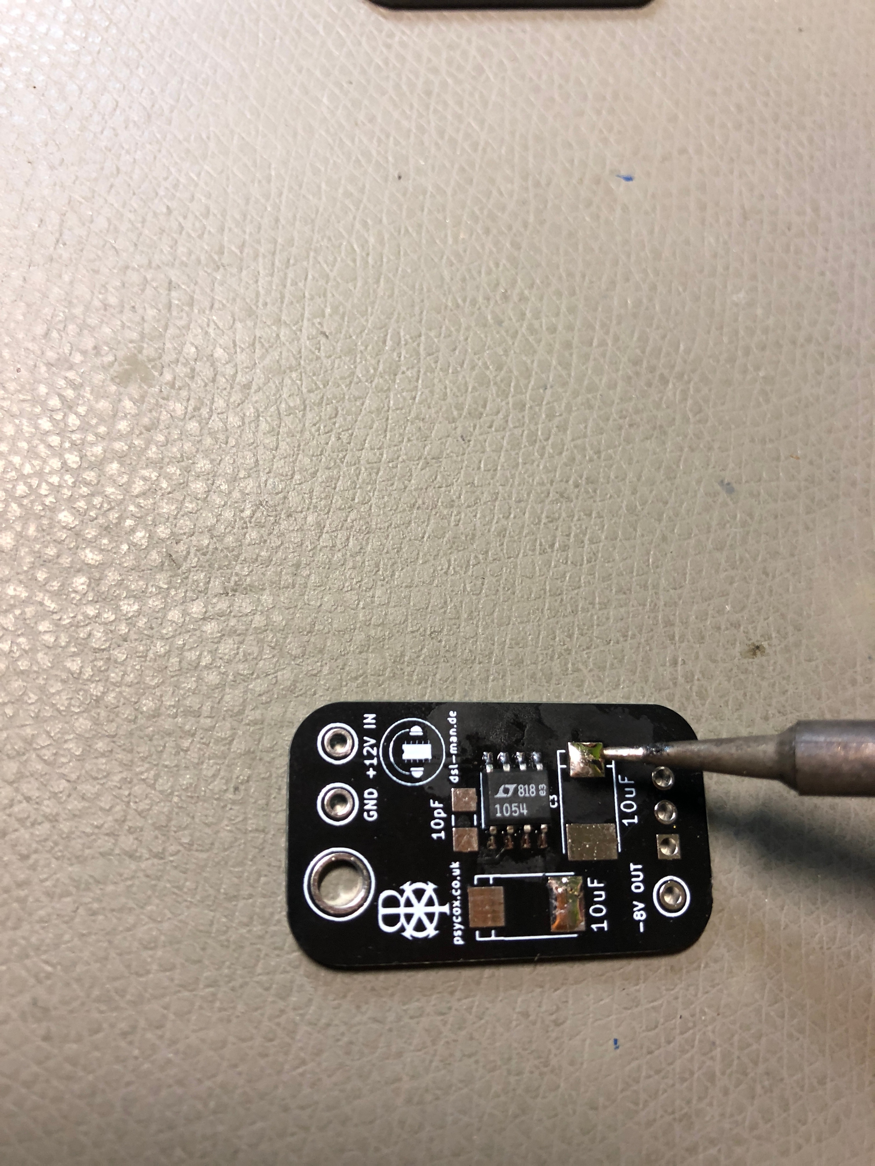
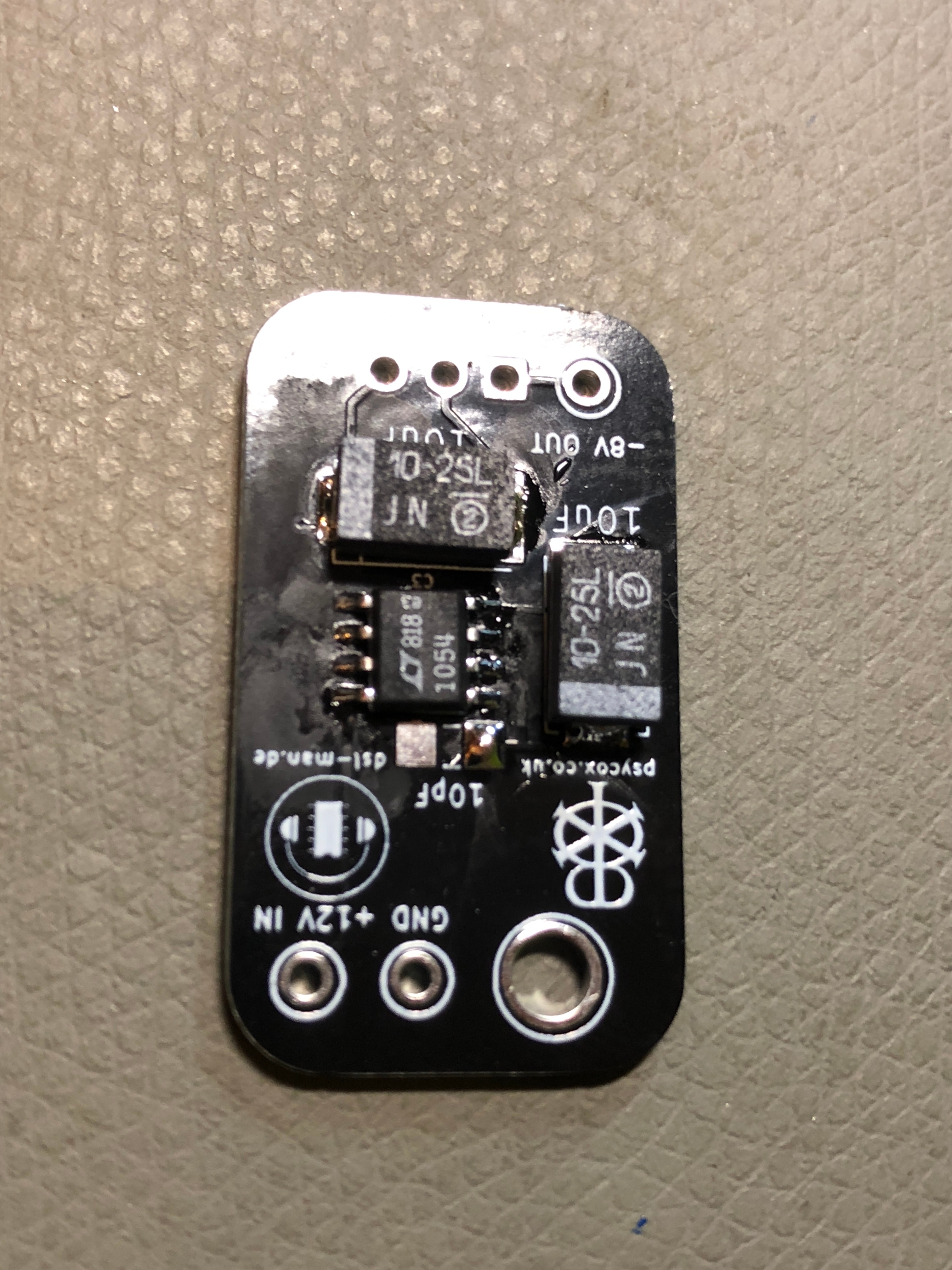
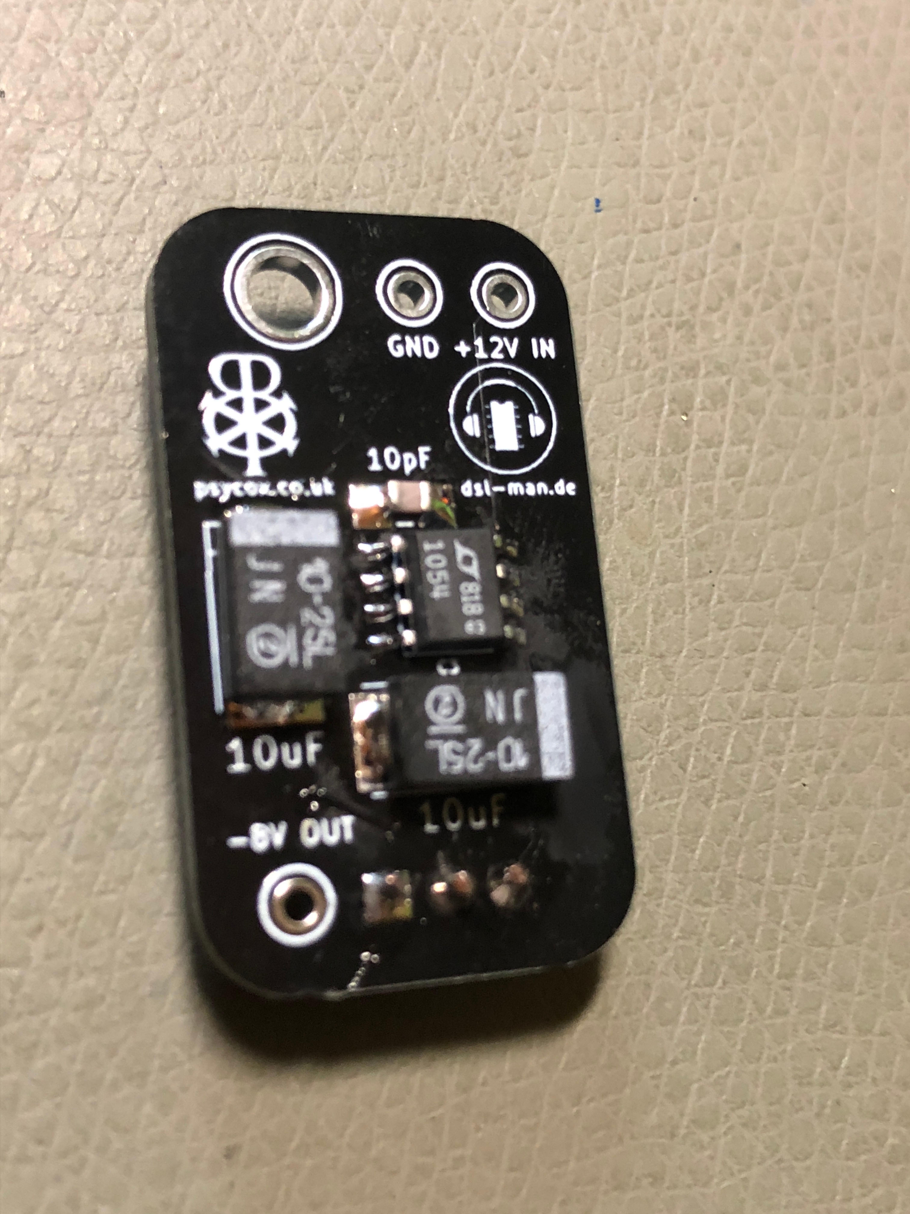
- solder the non polarity 10 pf capactitor on the pcb, start with one pad as described above
- turn the pcb
- bend the LM7908 pins to place it the shown orientation
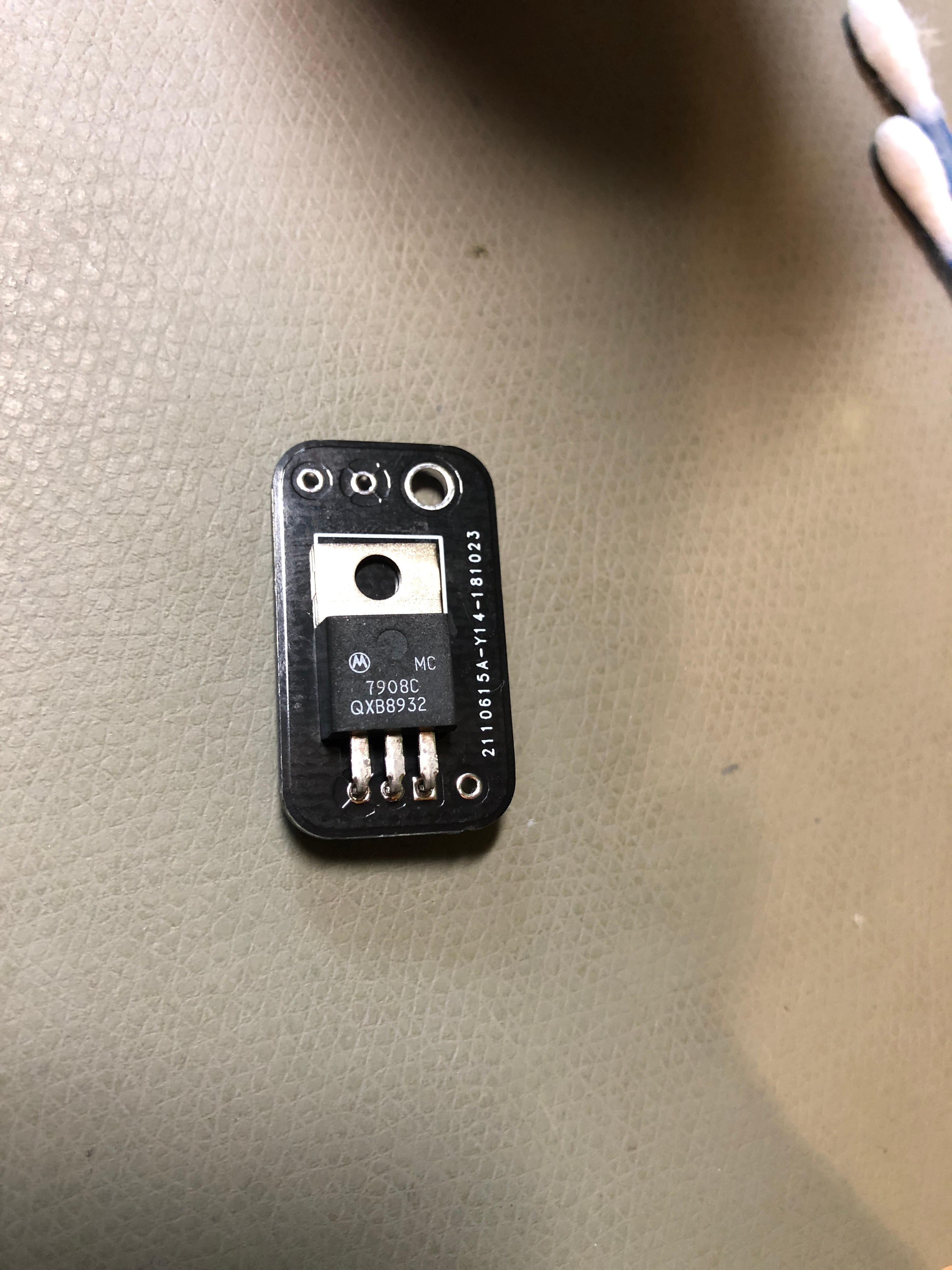
- solder all pins and check with a magnifier all pins
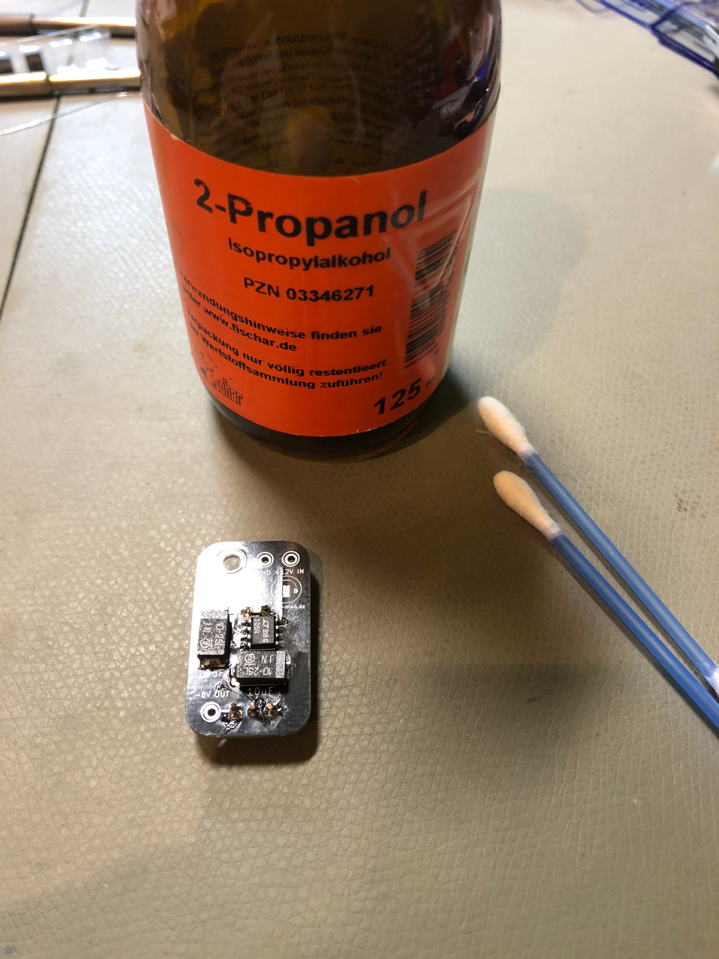
- clean the pcb with isoprop
...