...
| ID | Date | Bug/Issue/Improvement | affected part/pcb | Issue | Fix | reported by | reported to developer | Info from developer | affected version | fixed pcb version |
|---|---|---|---|---|---|---|---|---|---|---|
| 1 |
|
| modwiggler user | no | diy | this was a wrong issue !! | ||||
| 2 | 25.Jan 2024 | info | PSU | check that your PSU is still modified with other regulators my psu was still modified with the correct parts | just a visible check and keep in mind to test the psu later without attached Device/pcbs | Patrick | no | diy | ||
| 3 | 25.Jan 2024 | build info | Voice and Voice Motherboard | you have to respect that the MOLEX connectors on the Voice Motherboard and Voices have to installed in one step. You cannot start with soldering the molex connectors at the pcb without align it against the opposite part. do this:
| do not install the molex for now on voice card and voice motherboard, ill update this issue point later | Patrick | no | |||
| 4 | 27.Jan.2024 | BOM failure | Voicecard | Voice Cards BOM lists 1.5M resistor for R7 and R45, but those are already filled with 49.9K resistors as per the BOM and the schematic | wait on validation, DO NOT INSTALL R7/R45 do not populate R7 and R45 | Stuck and Patrick | not validaded now | BOM 1.0.3 | ||
| 5 | 27.Jan.2024 | Bom failure ? | Output board | On the Output board - R22 isn’t listed on the BOM, schematic says 2.2K | wait on validation | Facebook Sduck | not validaded now | BOM 1.0.3 | ||
| 6 | 27.Jan.2024 | Info | Output board | C22 is DNP - do not populate | C22 is DNP - do not populate | Facebook Sduck | not validaded now | BOM 1.0.3 | ||
| 7 | 27.Jan.2024 | BOM failure | Output Board | Q15, 16, 17, 18 aren’t listed on the BOM | is 2SC2878 | Facebook Sduck | not validaded now | BOM 1.0.3 | ||
| 8 | 28.jan 2024 | info | Voicecard | "Note that R140 and R141 are the preinstalled smt resistors on the back." | Facebook Sduck | BOM 1.0.3 | ||||
| 9 | 28.jan 2024 | info | Voicecard | "Brian for some reason doesn't list parts that are back in the "Rare Parts" list, so A3 is an CA3086N; A10, A12, A13, A14, A15 are all AS3080E; and A18 and A19 are AS3310." | Facebook Sduck | BOM 1.0.3 | ||||
| 10 | 28.jan 2024 | info | Voicecard | "There is one wrong sized hole on the bottom row of holes for the molex connectors. In one of the videos Brian suggests using a dremel tool to grind down the size of the affected pin, which I tried and it was relatively easy and worked well. I suppose you could also drill out the hole, but you would then also drill out the solder pad, and would need to run a wire jumper from the affected pin to one of the vias to make that work." | Facebook Sduck | BOM 1.0.3 | ||||
| 11 | 29.Jan.2024 | info | Voice MOBO | 30k resistor bag is labeled with quantity of 32 - in Altium is 24. | 24 are required - BOM 1.03 correct, just the bag is wrong | Patrick | valid - | |||
| 12 | 29. Jan.2024 | info | Voice MOBO | 100nF caps 20 in bag and labeled with quant. of 20, BOM is quant. of 18 and in Altium | 18 required - Bag is wrong | Patrick | ||||
| 13 | 29.Jan.2024 | Important Info | Voice Mobo | dort remove the pcb stripes (from pcb fab - panelized pcb) in case you use a solder frame. otherwise the traces can be damaged | Patrick | |||||
| 14 | 29. Jan 2024 | improvement | Voice Mobo | use 1/4W 0.5W watt 0207 Format resistors for R66/R67 to improve thermal noise | use 1/4W 0.5W watt 0207 Format resistors for R66/R67 to improve thermal noise | Patrick | ||||
| 15 | 5.feb 2024 | bug | Voice Mobo | U2 wrong silkscreen orientation | install in this way
| Patrick | ||||
| 16 | 07.feb 2024 | Important Info | Output Board | Install R7 and R7 with few millimeter distance against the PCB to avoid Thermal Issues | Install R7 and R7 with few millimeter distance against the PCB to avoid Thermal Issues | Brian | valid Yutube video | |||
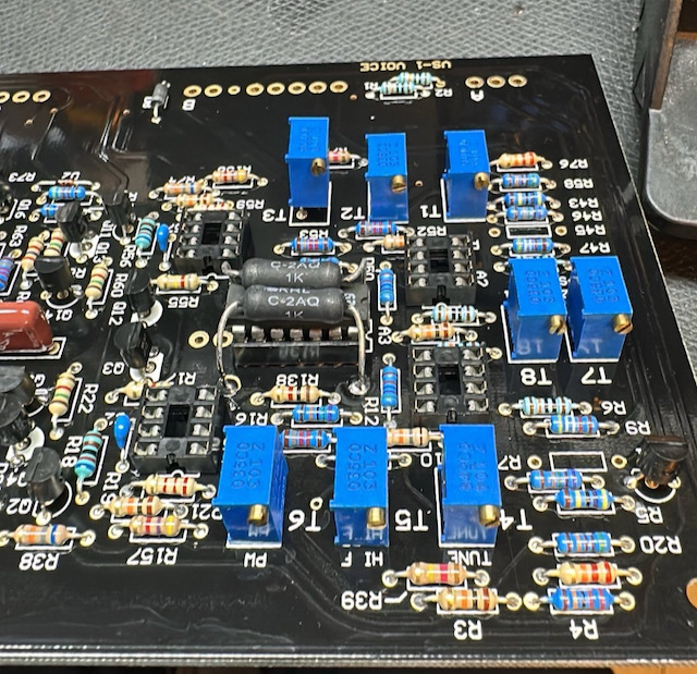
| 17 | 07.Feb.2024 | Important Info | Voice | Since we have to trim the Voices by Trimmers from Top, its not possible for 2 Trimmers when you have installed IC Sockets for A3 (Expo CA3086/CA3046) | Do not install a IC Socket for A1 in case you still installed a IC Socket, desolder 2 pins of T3 and pull the trimmer out as shown
| Patrick | valid | |||
| 17 | 07.Feb.2024 | Important Info | Voice | Since we have to trim the Voices by Trimmers from Top, its not possible for 2 Trimmers when you have installed IC Sockets for A10 | Do not install a IC Socket for A10 in case you still installed a IC Socket, desolder 2 pins of T9 and pull the trimmer out as shown
| Patrick | valid | |||
| 18 | 07.Feb.2024 | Tip | all PCBs | do not clean the Styrene Cap with Isopropyl - the Capacitor is glued and can be damaged |
| Patrick | ||||
| 1819 | 07.Feb.2024 | Tip | all PCBs | Do not wash the Trimmers, install the Trimmers and styrene Cap on Voice Card at the end and |
| Patrick | ||||
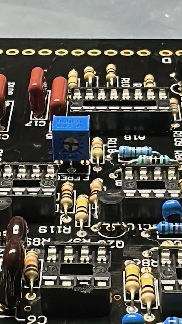
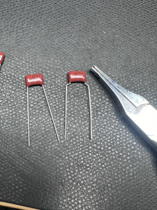
| 20 | 07.Feb.2024 | Tip | Voicecard | for better Installation and to avoid a broken capacitor due to mechanical stress bend the pins for C19 and C12 | on left original, on right bend style
| Patrick |
Pictures from kickstarter (link)
...