...
(All right - so far I have given adjustment directions without reference designators, and therefore needed a lot of pictures to describe where the probes go, and which pots have to be adjusted. Meanwhile I have a consistent set of drawings - schemos and components on boards - with reference designators, so instead of drawing a lot of pictures, I'll just refer to component numbers and pin numbers.)
4th Step: CV Rejection of Compander Adjustment
All referring to Main board (PCB 1).
Without any audio connected to any signal input, we're now feeding a signal to the CV path of the compander. For this, temporarily attach one side of a 10k resistor to pin 6 of U14, and feed a square wave of approx 100Hz, 1Vpp to the other side of the resistor. Exact values are not critical at all. You can also feed 5Vpp via a 47k resistor instead - you get the idea.
Now, put a probe to the CmpOut jack and adjust R106 until the signal is minimal. (It won't disappear completely, which is no problem; just minimize it.)
In a similar way, probe SumOut jack and minimize signal with R127.
Same procedure, probe DiffOut jack and minimize signal with R114.
Remove the resistor and 100Hz feed from pin 6 of U14.
5th Step: Level adjustments
Locate the two 3-pin connectors (for jumpers) near Pin 14 of U10 and U12 (the two 1496 chips).
Plug the jumper onto the two pins that are closer to the 1496 chips.
(These jumpers will be left in permanently for using the frequency shifter - do not remove them after the adjustment.)
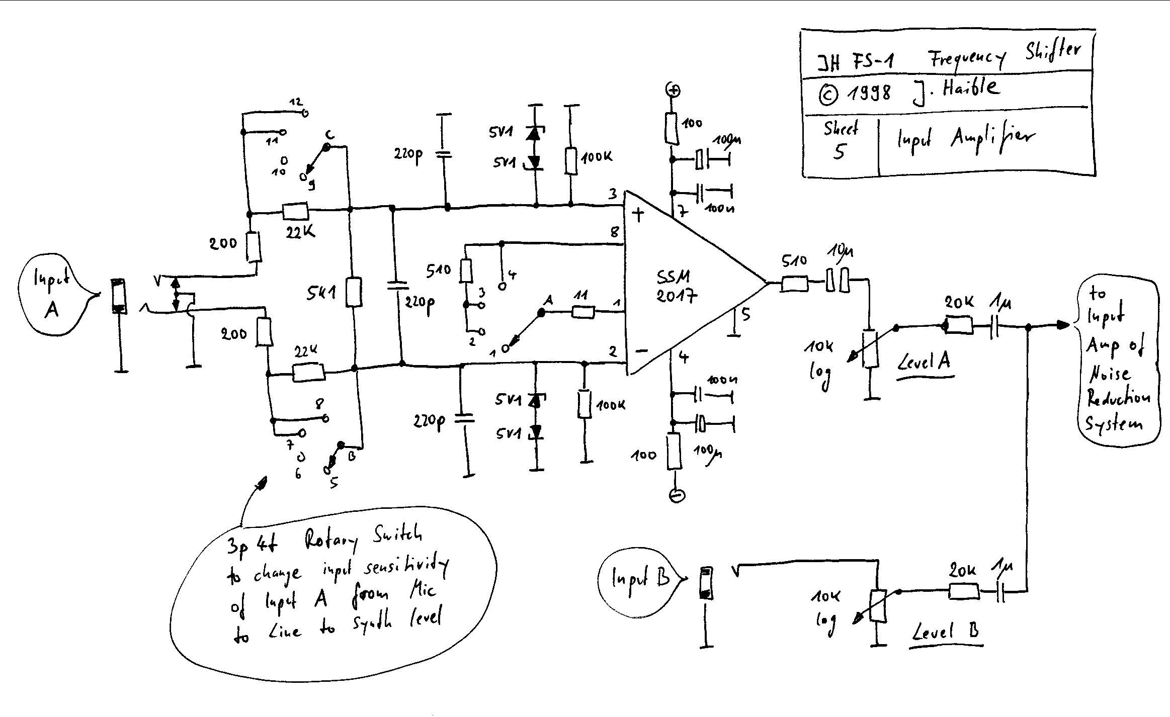
With PCB 1 and PCB 2 connected together (signal goes from PCB 1 to PCB 2 via CmpOut connectors, and returns to from PCB2 to PCB 1 via SigSin and SigCos connectors, and PCB 1 getting its Input from the preamp on PCB 2), feed a signal of approx 1kHz (sine wave recommended) to the Frequency Shifter (Mic input or Aux input) and adjust the level until you get an unclipped signal of 5Vp at the DryOut connector of PCB 1.
Then adjust R99 to get approx. 5Vp at the CmpOut connector.
Probe SumOut and DiffOut connectors and play with the Frequency settings of the Quadrature Oscillator (Range and Manual potentiometers); see how the frequency is changed. (There may be some side effects, i.e. not a pure sine wave, at this point.)
Adjust R123 to get approx. 5Vp on SumOut.
Adjust R110 to get approx. 5Vp on DiffOut.
6th Step: Balance
In the previous step, you may still have some amount of the adjacent side band in yout frequency shiftet output, which appears as a slight amplitude modulation in the frequency shifted sine wave. You can minimize this to some degree with R133 for the SumOut, and with R115 for the DiffOut.
In practice, you probably won't hear much of it, and you cannot cancel it precisely for every amount of frequency shift, but it's a good idea to minimize it. Otherwise, just leave R133 and R115 in mod position.
Adjustment Finished!
Quadrrature VCO from fs1a:
- more addional Infos here too: http://modularsynthesis.com/jhaible/shifter/jhshifter.htm
...
