...
https://modwiggler.com/forum/viewtopic.php?t=242243


- You
...
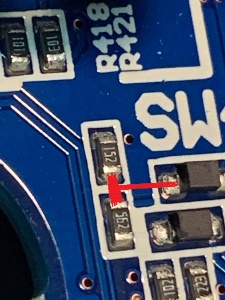
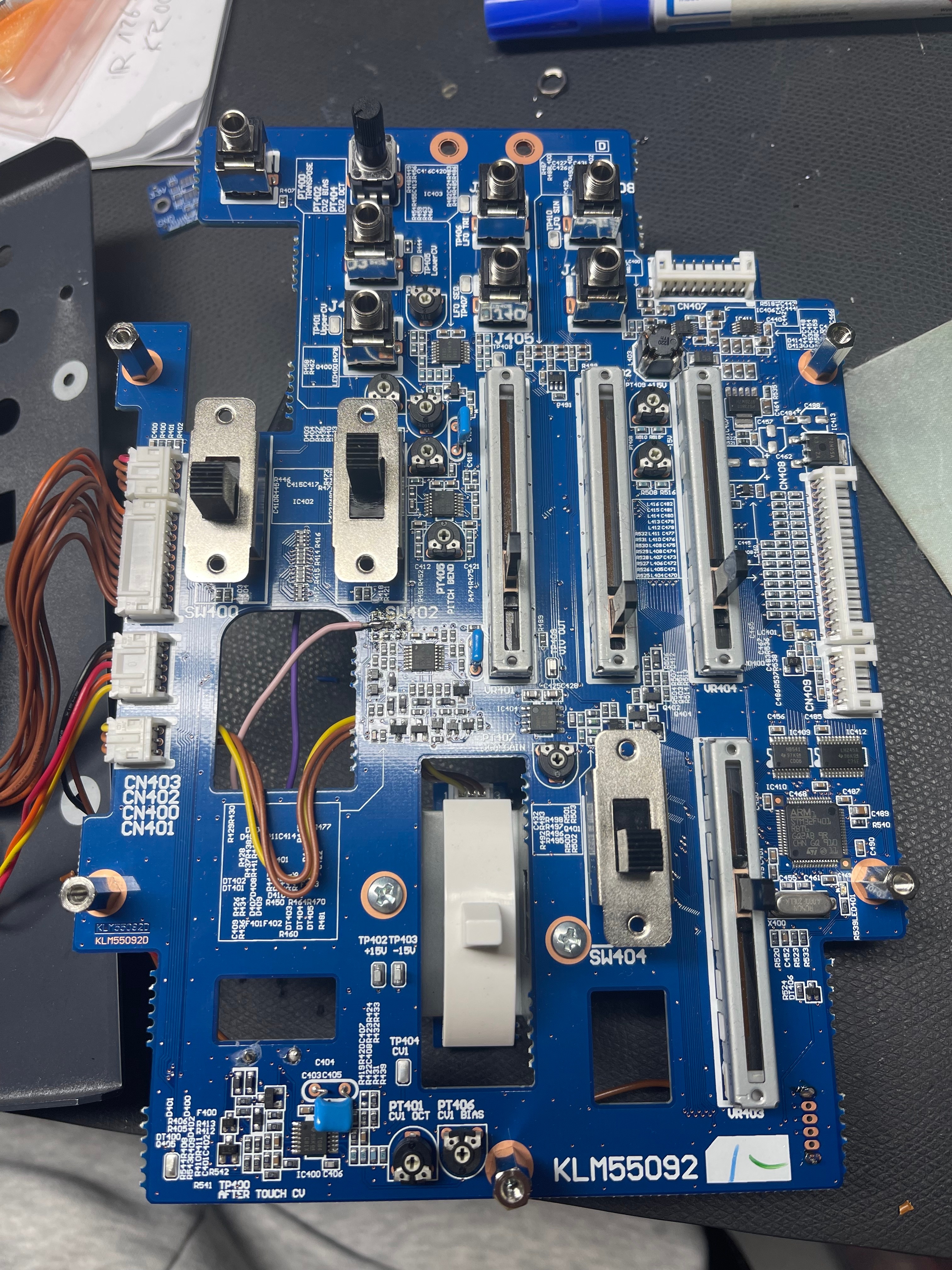
- have to remove R444 on the top side:
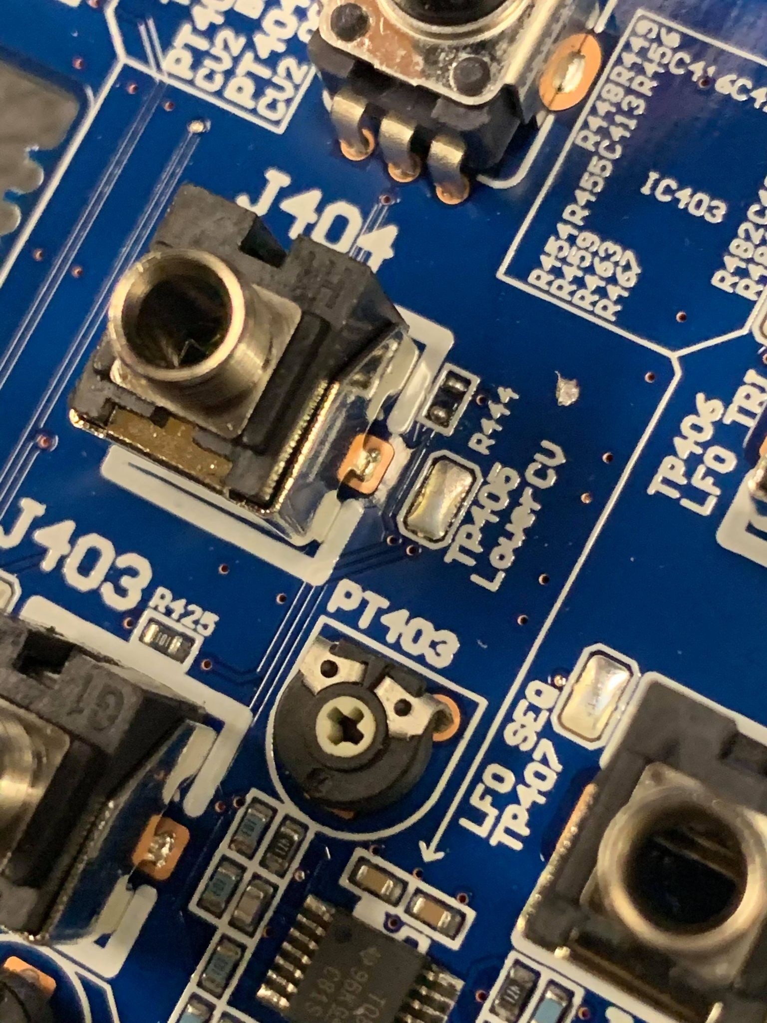
the 2. the resistors marked 152 and 562 and both diodes must be removed. IF YOU HAVE NOT WORKED ON SMD BEFORE STOP HERE! Get someone who has experience, please. This is a lead free, relatively delicate board. DO NOT ATTEMPT unless you have done this stuff before.
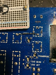
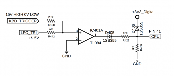
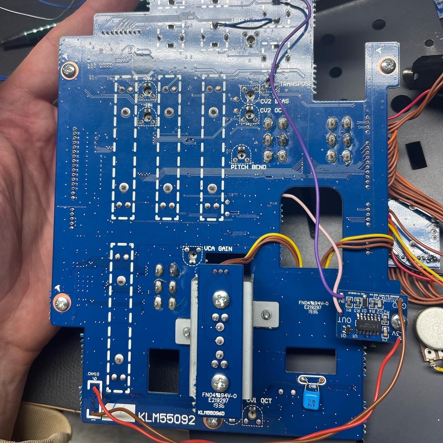
3. These three pads are where we are attaching the OUT of the above conditioning circuit. This point is the input to the MCU that it reads for the tempo of the sequencer/arpeggiator.
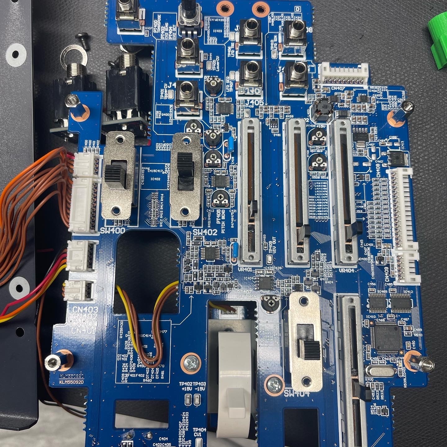
4. solder a cable from this point to the mod pcb out.
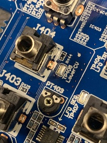
5. solder a cable from the upper CV jack (top) pin - to the input of the mod pcb
6. solder a wire/cable bridge from upper Cv jack (bottom pin)
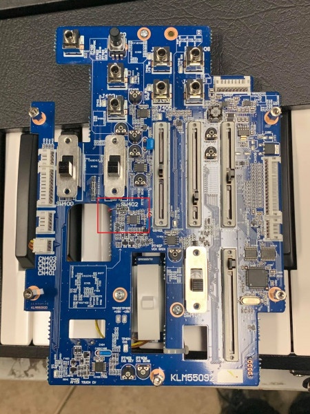
7. solder power input and ground as shown in following pictures (there are unused pcb connections on bottom of the pcb) marked as CN410, pin6 is positive power out and pin1 is GND) which has to be connected to the Mod PCB.
before Modification:
This picture shows the installed Modification:
from a other build :