That’s not an official guide.
It’s more an best practice guide
- Sourcing parts, order higher quantities to get the best price and more parts for free or for a better condition than ordering later single parts and you have spares (tactile switch, encoder, potentiometer, opamps 3340,3360)
- Sort all parts, one carton with resistors, one for capacitors...one for mechanical parts, one for Ics/semis.
- Sort the values like 1R-999R, 1K-9.9K, 10K-99K.... same for capacitors
- Start with the mainboard and hardwareboard and next Breakoutboard and PSU.. so you left less plastic bags for the voices which makes things easier
- Use lead based solder core or you get trouble with the ground pads and in case of failure or wrong part placements it’s more complicated to desolder the part.
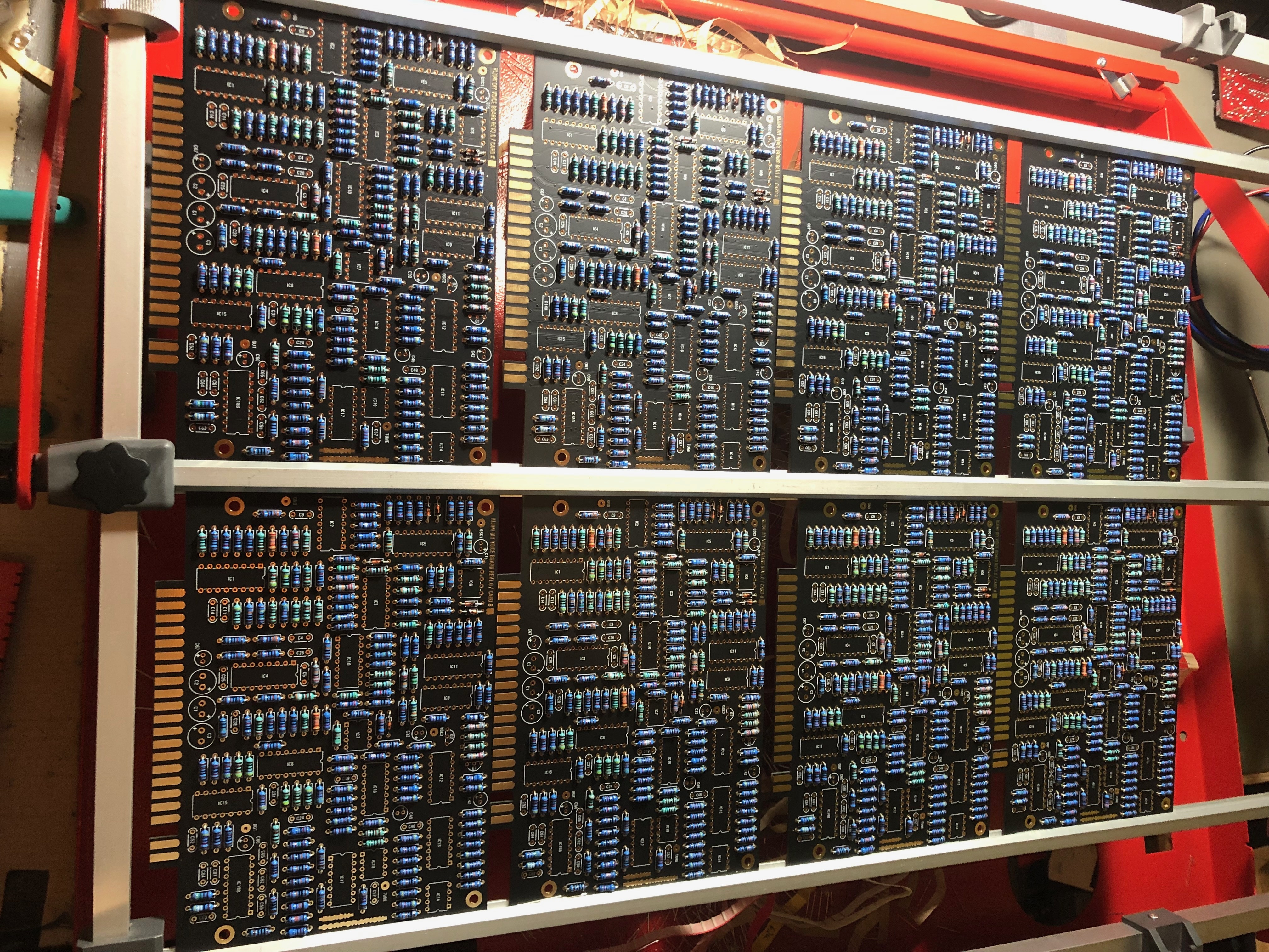
- Use for the voice cards a mounting frame which costs 50-250€.
- More later - please read carefully the page: KIJIMI Documentation this includes instructions about the firmware and known issues/tips
Hardwareboard (often called Mainboard by me) and Controlboard
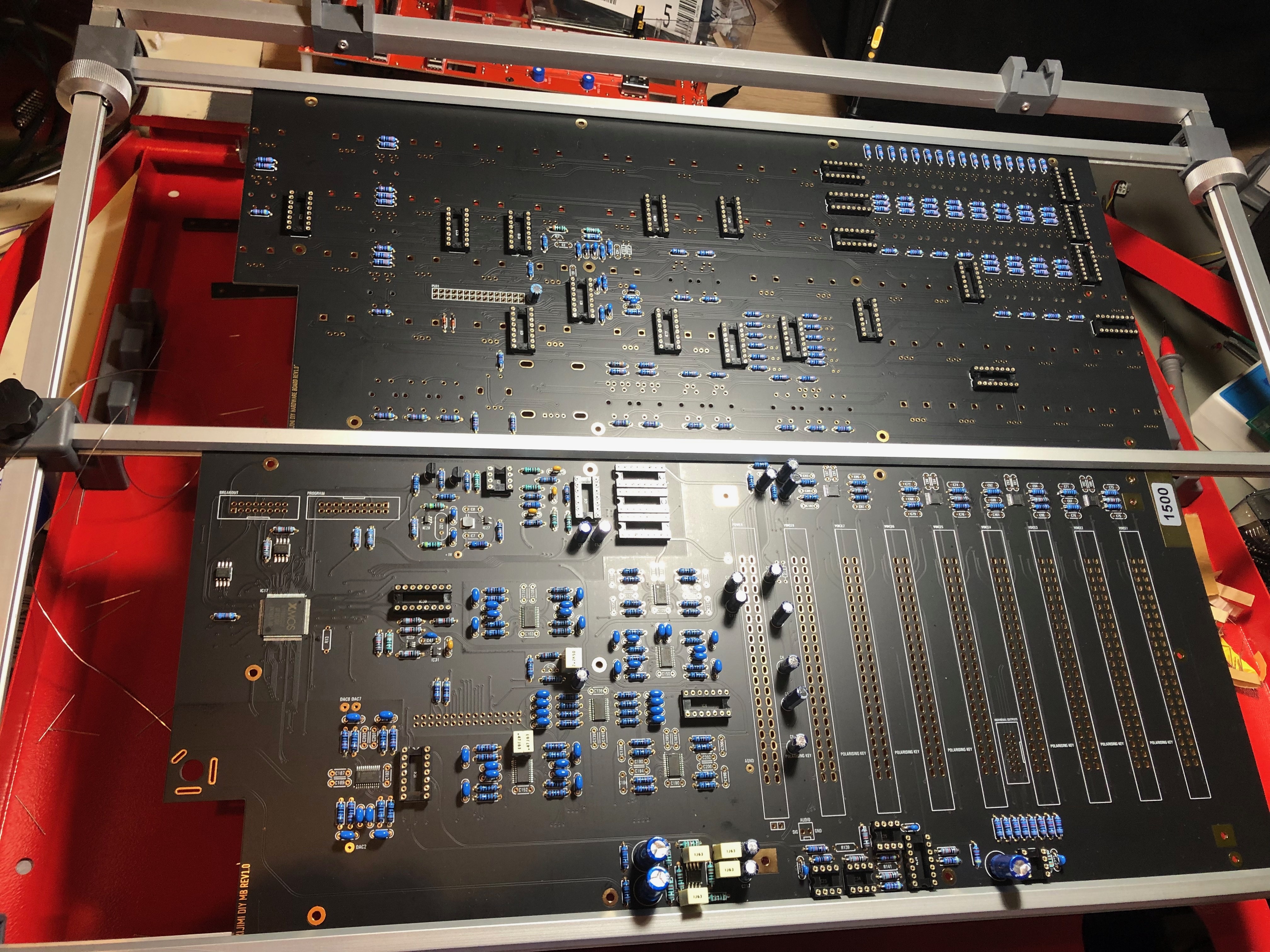
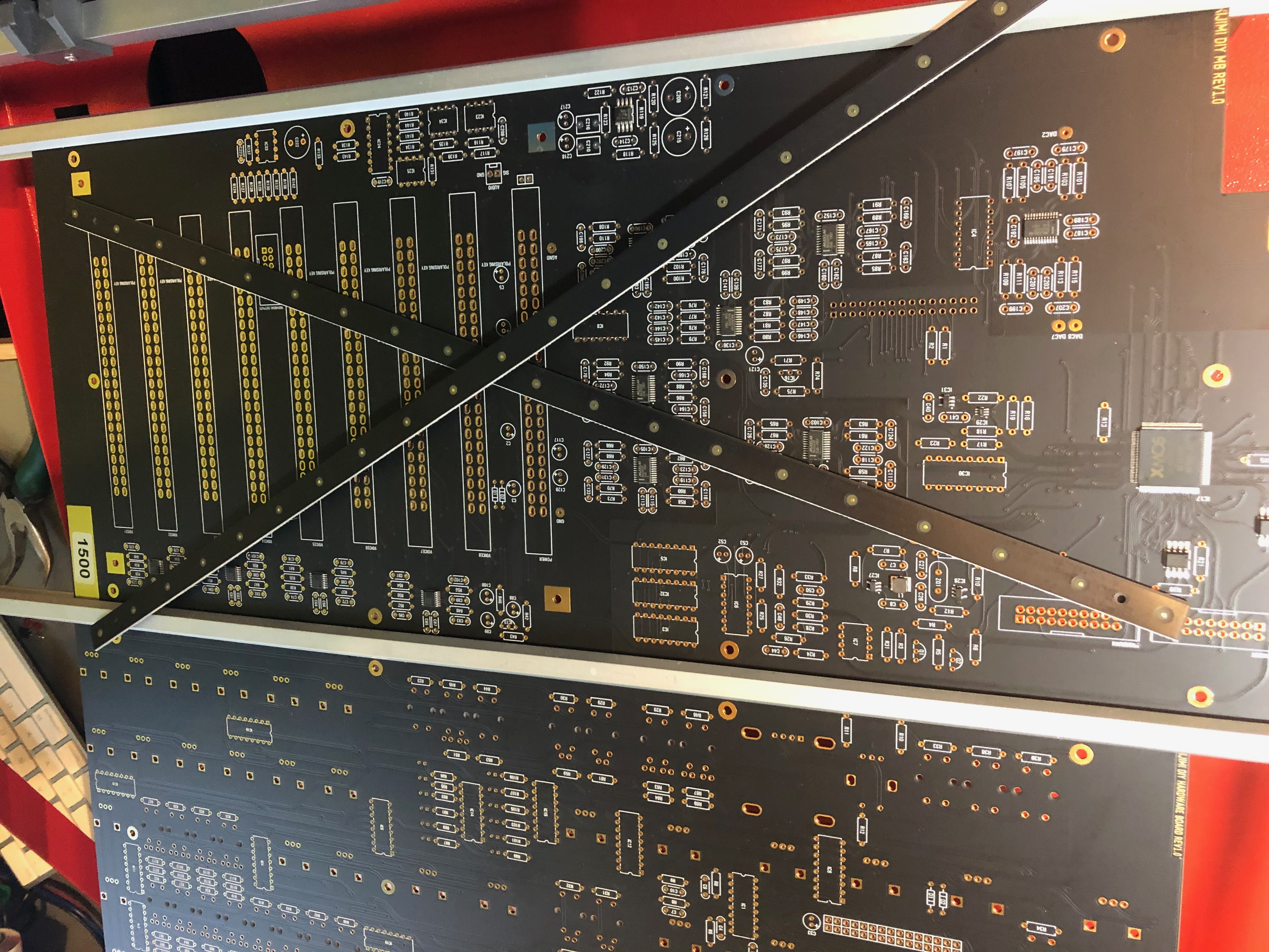
remove the PCB production (panelizing) stripes
100K resistors
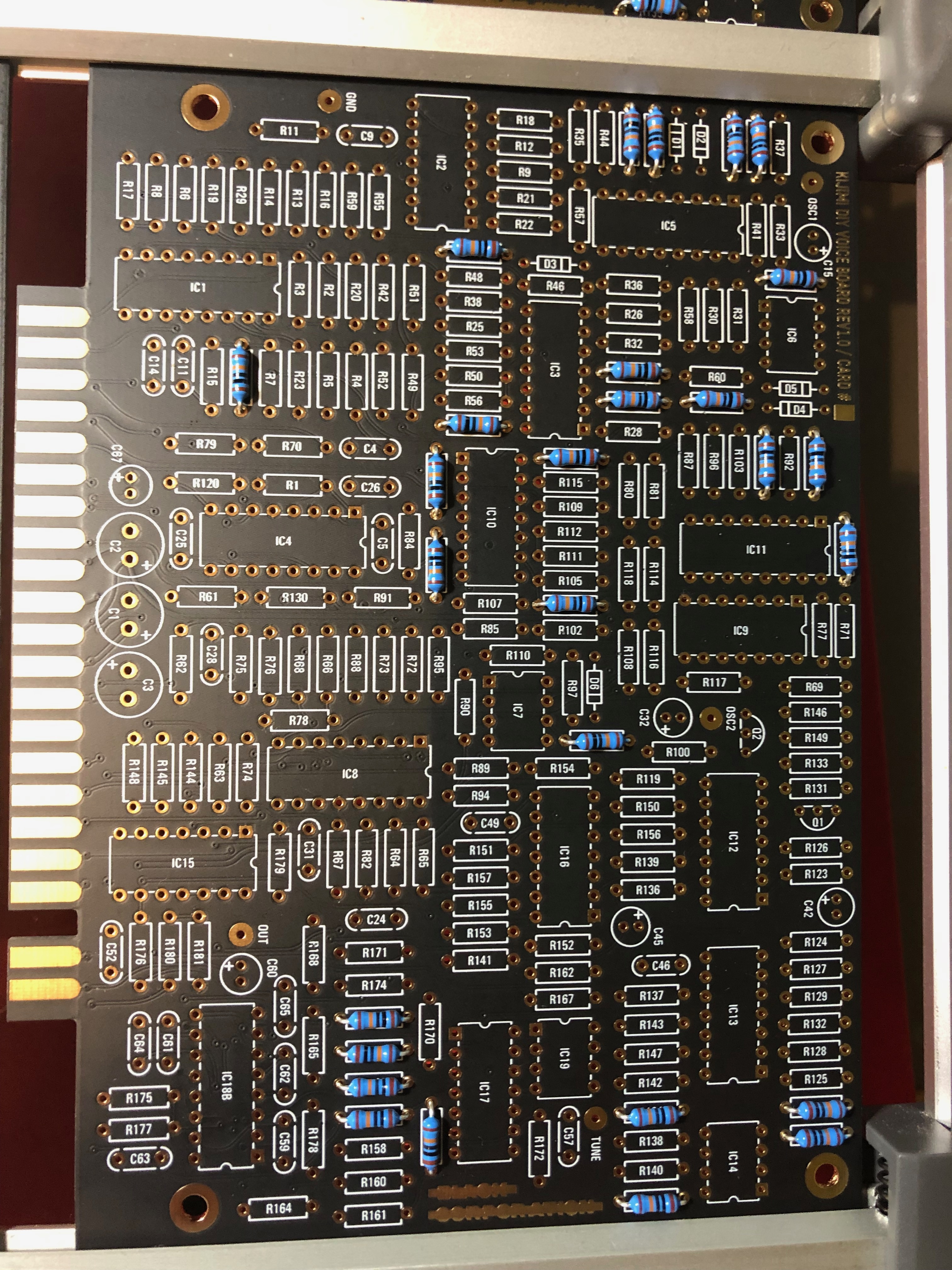
all resistors (the change from the lastest BOM wasn't included here)
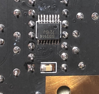
Dont install the IC socket on the location where you find on the nearside the SMT IC !! this socket isn't needed and its easier while soldering the SMT IC.
remove the panellising pcb parts from the mainboard/controlboard or it will not fit in the case later. (use a pliers and bend it carefully step by step)
Controlboard
The front panel distance to the controlboard is 6mm, use a 5mm spacer and a washer or you can also use 6mm, 12mm Spacers between mainboard and Controlboard.
At this hole : DO NOT mount at the rearside a 12mm spacer, only use at top side a 5-6mm spacer and from rear a screw/nut (depends on what you have on hand) otherwise a 12mm spacer will short the voice card slot pins
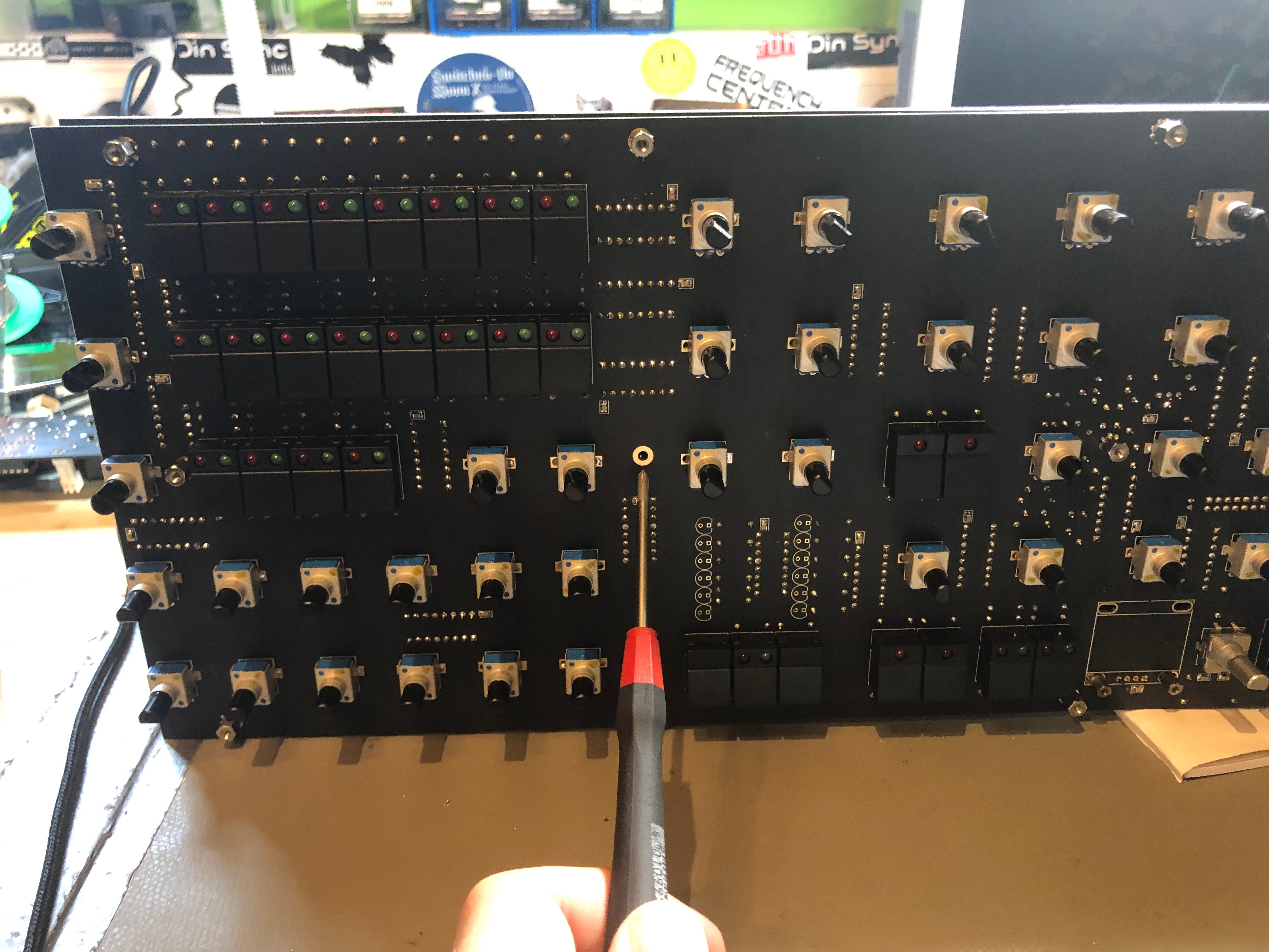
POTIS:
install all potis and solder only one pin, then check the orientation of all pots in a row - maybe you have to change the alignment.. solder a groundpad and check the orientation again.
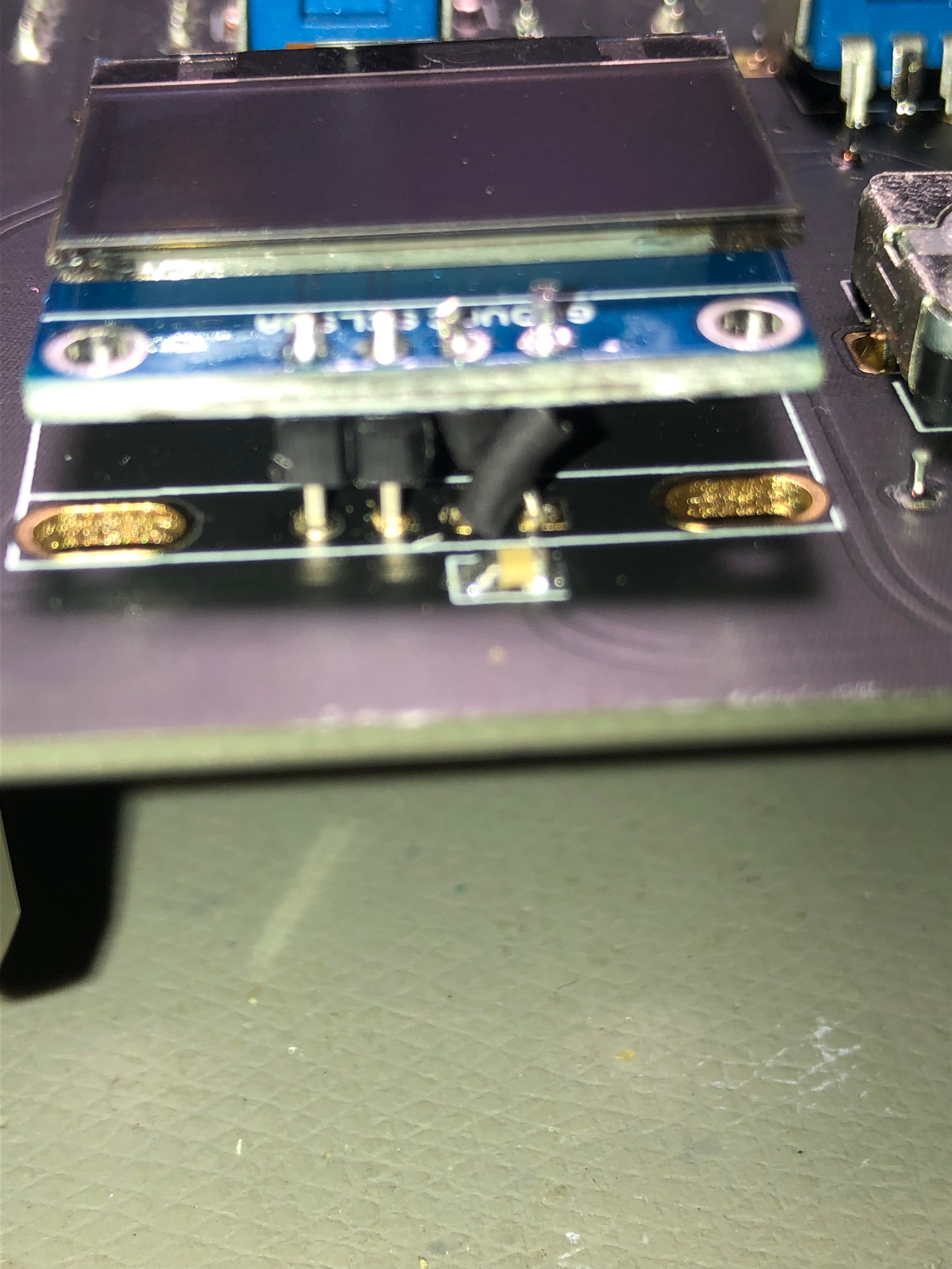
DISPLAY, make sure your pinout is correct - VCC-GND-SCL-SDA ! otherwise bend the 2 pins as shown in the picture and use shrink tube, double check it for shorts - or your 3.3V rail will be destroyed
dont install 5mm spacer between the display and PCB - you only need 3-4mm.. wait with the display until you have the front panel..
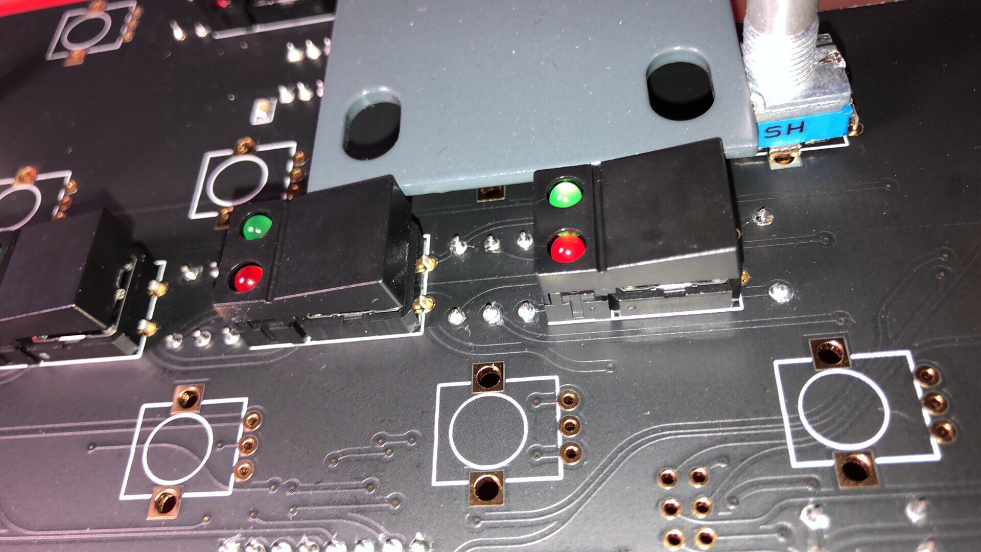
when you have the front panel: install all pots and all switches, put the OLED as shown in the place (dont solder it yet), put the front panel on the controlboard, fix the panel with screws,
the front panel must be in the same height as the switches or use washers/remove the washer to get the correct height. if everything is ok - solder the display at the outer pins and check the orientation again.
Current identified Errors/Omissions/Errata:
Date | Location | Identified Issue | Resolution | update |
|---|---|---|---|---|
| May 29, 2018 | BOM hw board | R119, R120, R121 not in BOm 1.02 | R119 4K7 R120 100R R121 2K2 | BOM project updated-1June2019 |
| May2019 | OLED DISPLAY | Double check the OLED pinout | rin case of wrong pinout - remove 2 oled pinheader pins and use a resistor leg and cable tube shrink correct is: VCC-GND-SCL-SDA | |
| BAT43 x2 missing D3 D4 on Harware board | BOM project updated-1June2019 | |||
| 12 Jun2019 | BOM hw board | C34 missing in BOM | 560pf mlcc RM5 | |
| 30 July 2019 | Controlboard | dont install a Metal spacer between controlboard and mainboard in the middle of the pcb - otherwise it touch the card slot adapter pins
| use only the short 7mm spacer and a screw/nut from rear. | |
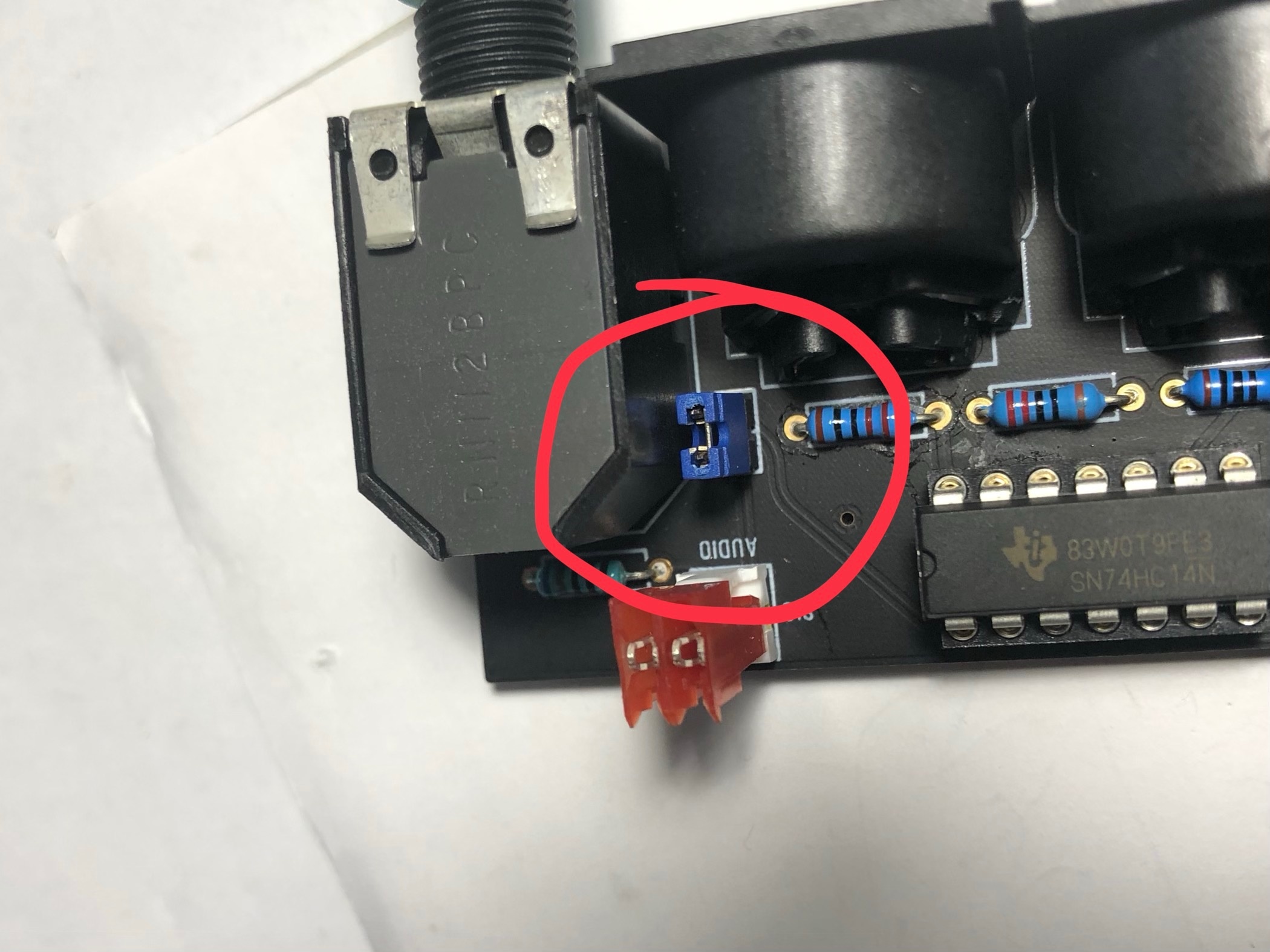
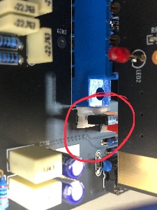
| 30 July | Audio output | install on both locations a jumper (bridge both pins) if you use the flat ribbon cable for the audio signal too. when you use the MTA100 headers with coax cable, dont install the jumpers. only connected at the mainboard side the ground, dont connect the GND at the breadboard MTA header - or you get a groundloop (more noise, risk of hum) |
| |
| 30 July 2019 | info | use a 24V Center positive Powersupply with 2Ampere or more | don't use the 12V PSU from DDRM DIY Version. | |
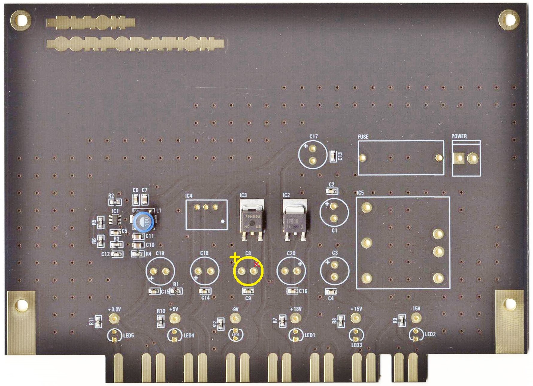
| 1 Aug 2019 | major bug | on the PSU card is the -9V Capacitor silkscreen wrong, this was happen on my PSU card and the capacitor leaked, thx to Ando for the picture. | install the positive pin of C8 on the left side (as shown in the bottom picture)
| reported to Roman and Bob |
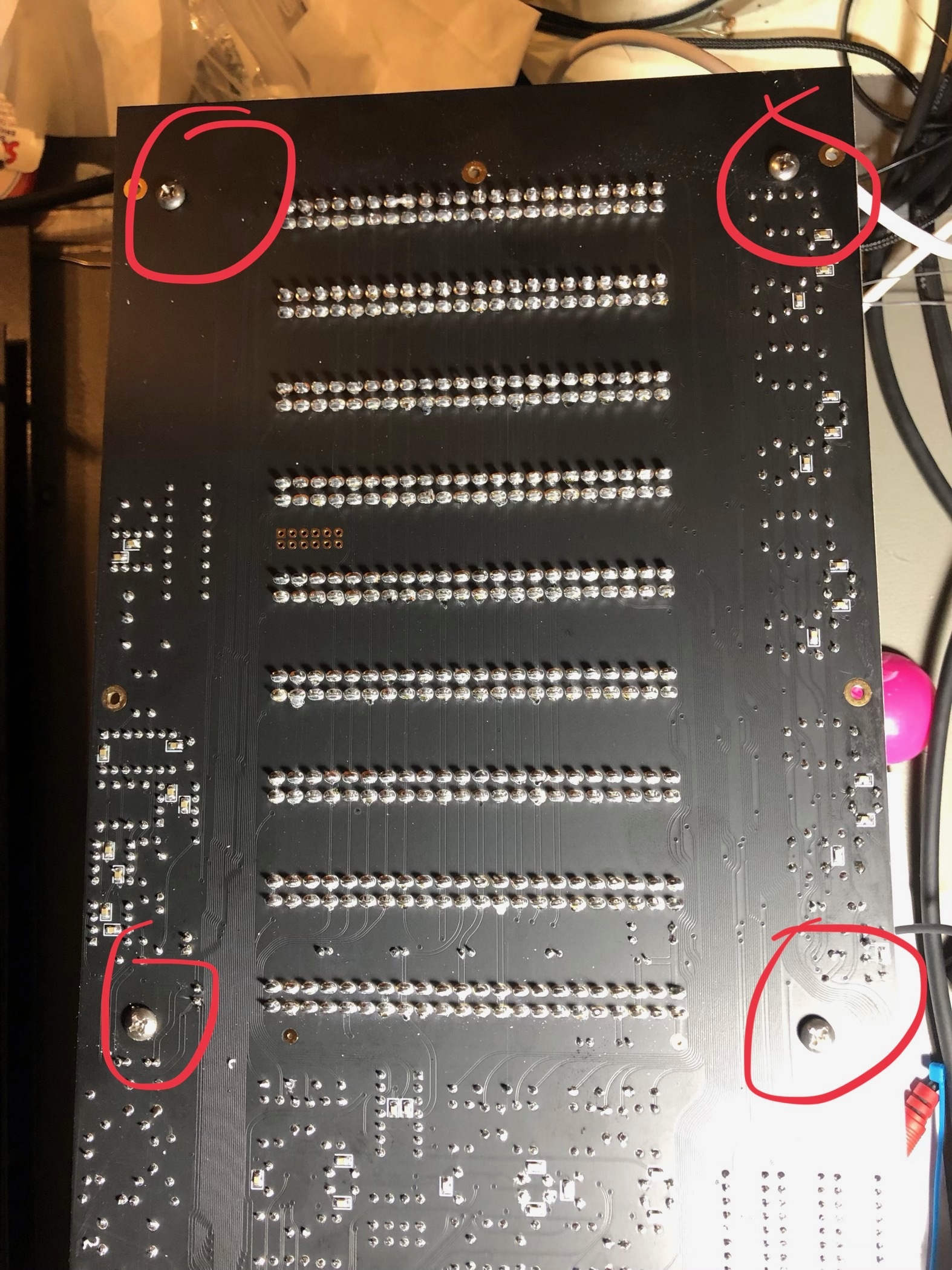
| 15 Aug. 2019 | mainboard | mounting holes for brackets do not fit with the Mouser screws. carefully drill a bigger hole as shown here: (marked) only this 4 holes |
| |
| 15 Aug | PSU | the fuse must be around 1.2Ampere, the current of the kijimi on 24V DC is 950mA |
Gallery Kijimi |
|---|
| There are no images attached to this page. |