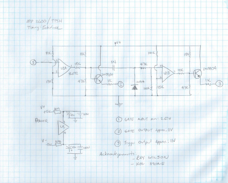
The TTSH needs a Gate AND Trigger signals signal with 10/11Volts, otherwise it wont work as designed in usage of the AR/ADSRwith external GATE Signals only.
here was the simple Solutionidea born:
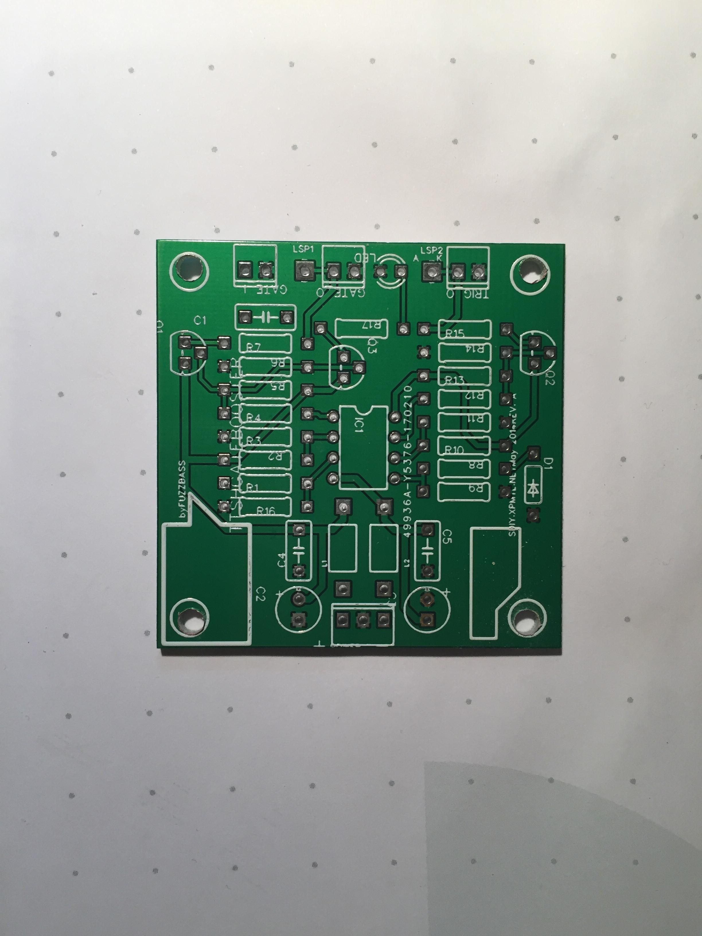
i offer offerin my shop the Gatebooster bare pcb for 8€ (shipping 1,50€)
assembled for 20€ (shipping 4€)
add 2,20€ if needed as registered shipping.
...
and the assembled Gatebooster version:
https://www.diysynth.de/?cat=c2_Pcbs---Panels-pcbs-panels.html
| Note |
|---|
in case of the version with midi implant |
...
connector, connect a 1M resistor from ground to Pin3 of TL072 |
...
preferred Solution:
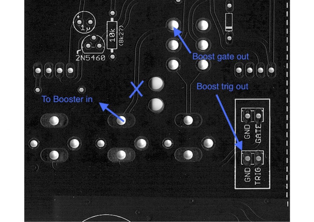
use a screwdriver or other sharp tool to cut a trace - marked with a blue X in the bottom picture. (dont drill a hole - its a 4 layer pcb)
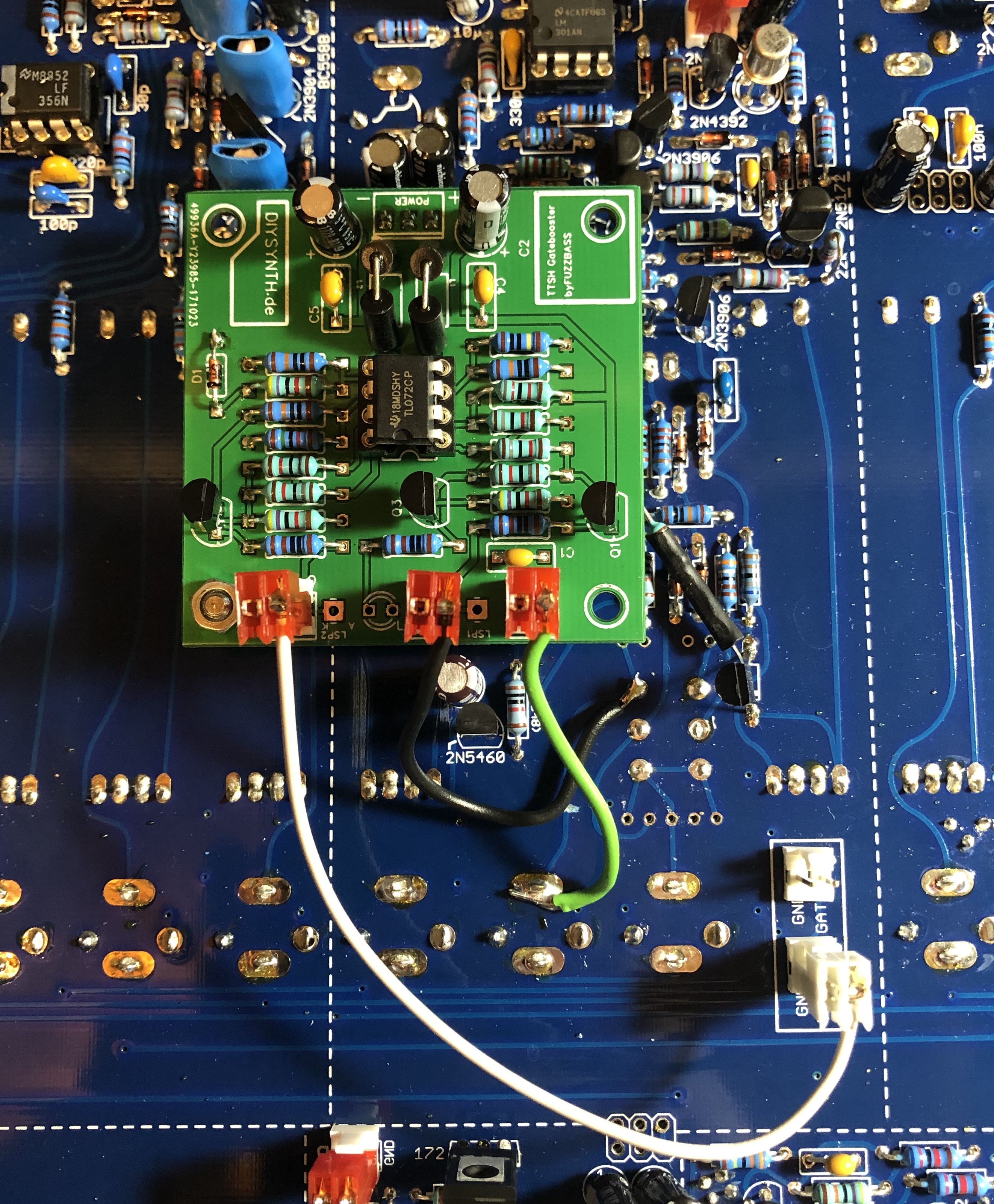
Connect connect the gatebooster input with a cable from the GATE Input jack from the ttsh. (its needed to cut the trace from the S/H/Gate switch)
( ignore the boost trig out pointer on the picture - use the TRIG instead of GND ![]()
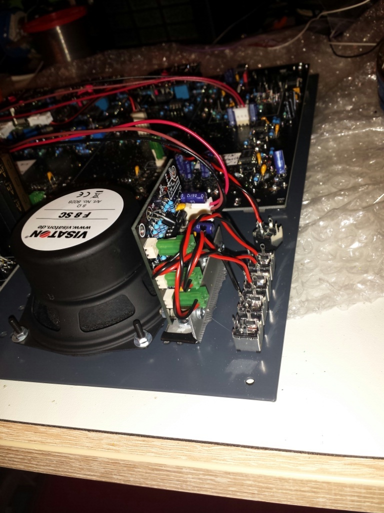
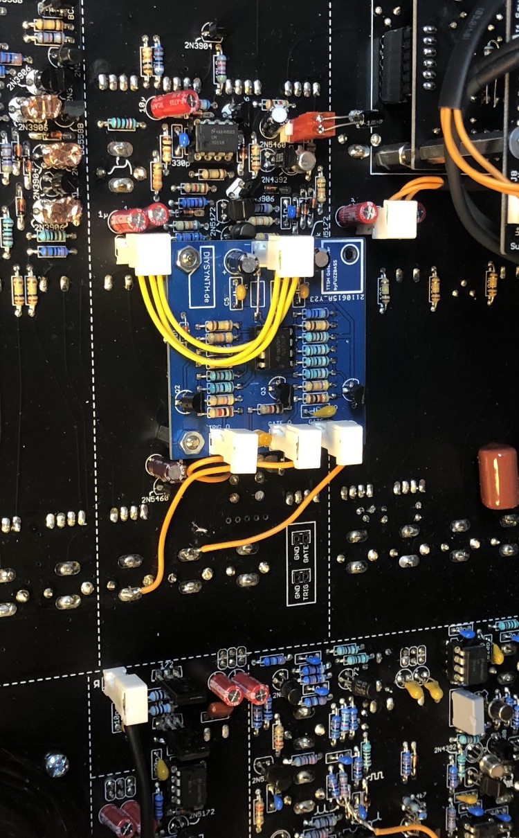
for Rev.1 use the speaker holes to mount a bracket
connect the the TRIG header to the TRIG on the gatebooster.
You don´t need the GND pins ! (except for power)
Install a 3 pinheader in the 6 pol pinholes on bottom of the 2x 1uF electrolyte capacitors in the ADSR section and put the gate booster pcb power input on this 3 pin header.
the pcb sit on top of the IC from the AR section. make sure your gate booster pins don't touch any other parts. if needed install a 10mm or 12mm metalspacer as shown in my picture (on left bottom hole only)
other solution for external usage
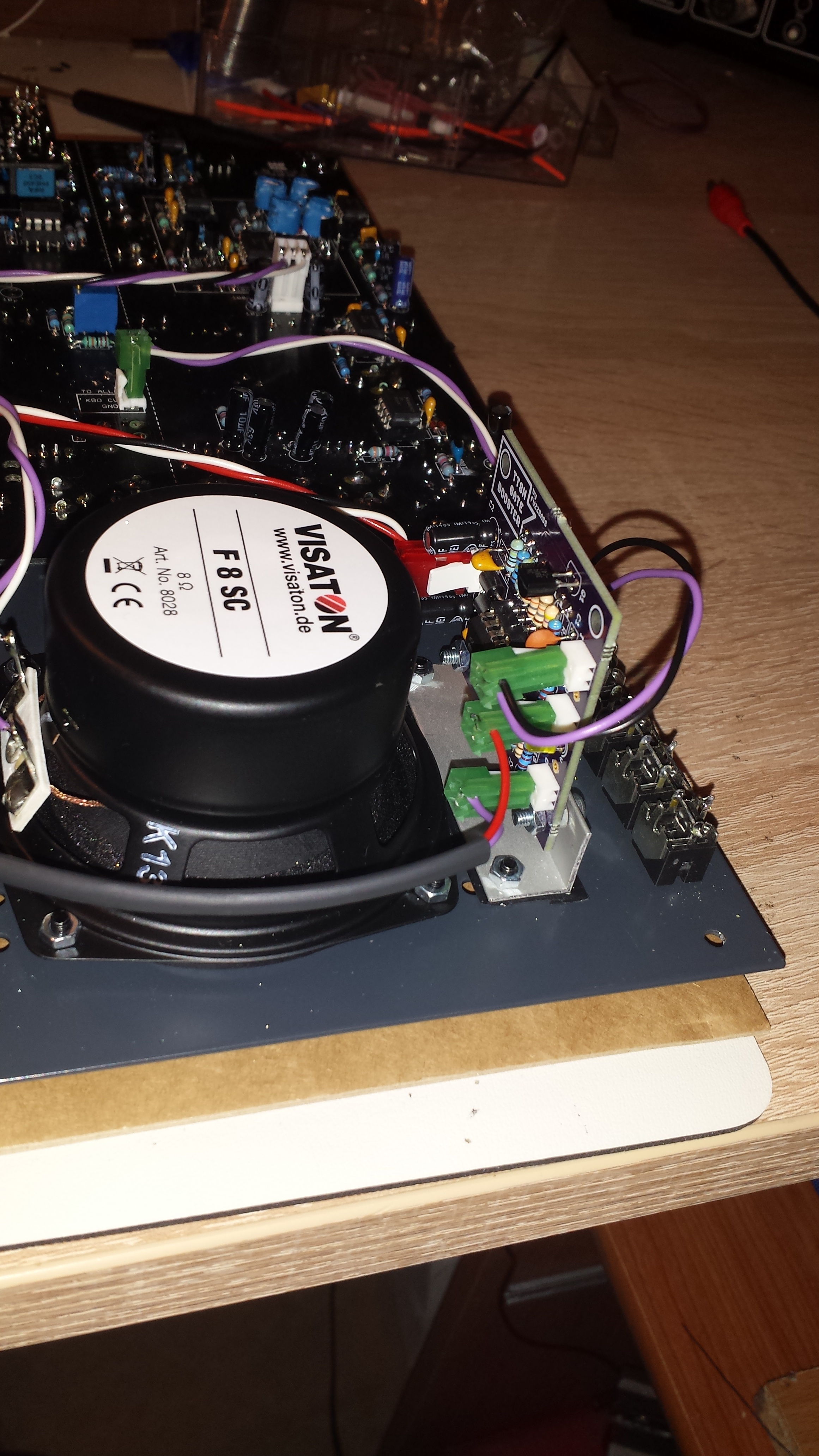
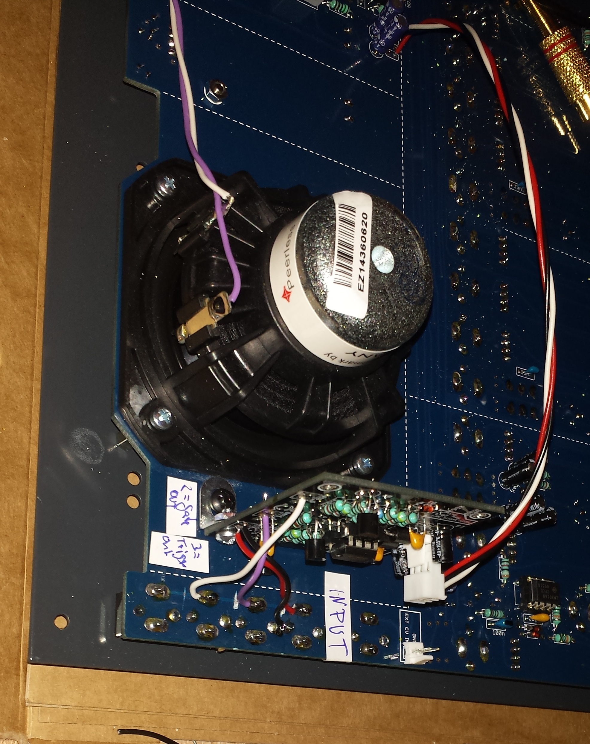
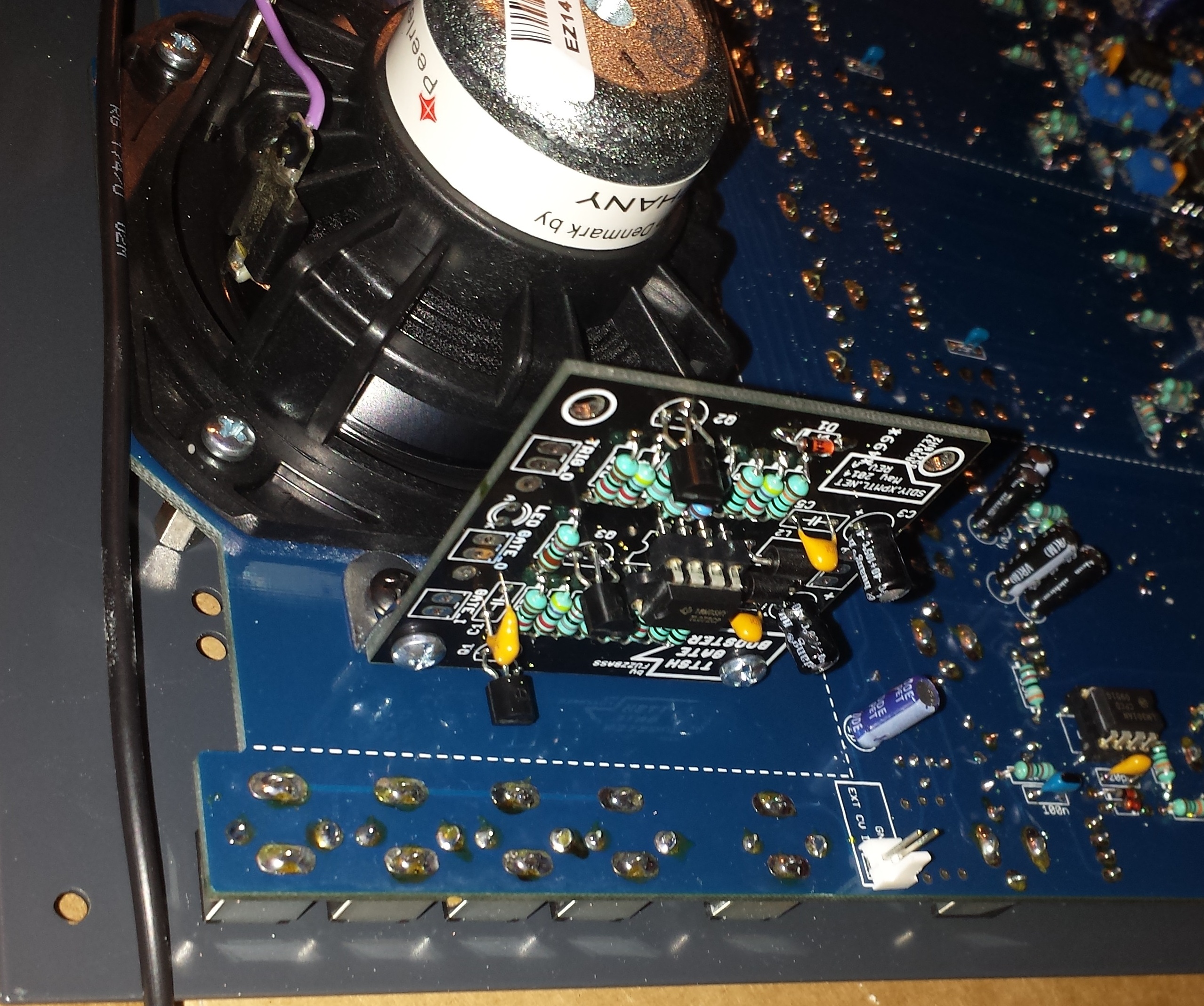
This Solution use 3 jacks of the multiplesfor rev.2 :
drill 2 holes in the pcb and mount brackets with woodscrews, cut the TIP/HOT traces for 3 jacks on pcbat multiple connectors , use one ground (you dont need 3 grounds) run wires from gatebooster to the tip of the jacksconnect the cables (gatebooster input, gate output, trigger output)
connect the gatebooster use power from a module section (there are 6 solderholes, 2x3 rows - test with a voltmeter the voltage output/polarity) run powercable to the gatebooster.
Theory:
|
|