| Section | ||
|---|---|---|
if you like my work, feel free to use my paypal gift function
|
Subpages:
| Children Display |
|---|
Page History:
| Date | Autor | Change | |||||||||||||
|---|---|---|---|---|---|---|---|---|---|---|---|---|---|---|---|
| 09.May 2018 | LED-man | Initital - Structure | |||||||||||||
| 28.May 2019Oct 2020 | LED-man | BOM added | 30. July 2019 | LED-man | Global content updates | 1. August 2019 | LED-man | major bug | 7.January 2010 | LED-man | Windows install Methode Firmware added | 24.March | LED-man | new Firmware 1.2.0 releasednew structure |
Table of Contents
| Table of Contents | ||||
|---|---|---|---|---|
|
https://soundcloud.com/paul-schilling/kijimi-polykobol-127-cos
| Widget Connector | ||
|---|---|---|
|
| Tip | ||
|---|---|---|
| ||
"As Synthtopia reports, the Kijimi is inspired by the sound of the RSF Polykobol, a rare French polysynth from the late ’70s that was only available in very limited quantities. According to Instagram posts from Black Corporation, the synth will be available both pre-built and as a DIY kit." source: http://www.factmag.com/2018/04/03/black-corporation-kijimi-synth/ |
| Panel | ||
|---|---|---|
| ||
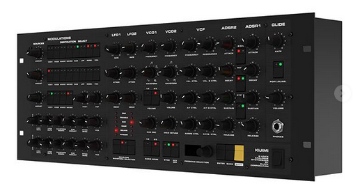
the KIJIMI Synthesizer is a product of the Black Corparation located in Tokio. It´s available in 2 different Version:
The DIY kit consists of 12 PCBs:
The motherboard has the MCU and DACs (digital to analogue converters used to control the analogue circuitry) preinstalled, the remaining parts you have to buy yourself from a local supplier. Some DIY shops will provide full parts kits. Most of the remaining parts are thruhole, except for power filtering ceramic capacitors, which are large (0805 size), all same value (0.1uF) and located on the opposite side of the thruhole parts on the PCB. The frontpanel and rack case will be supplied by DIY HUB. |
Kijimi Article on Amazona.de - written by me:
https://www.amazona.de/test-black-corporation-kijimi-synthesizer-diy-report/
Buildguide
not complete yet, but its better than nothing
BOM:
new BOM from July 2019 with improved Sound, i renamed the File because Roman used the same Filename as before which can confuse and ends in mistakes when you open accidentally an older file with same name.
BOM from 23.July 2019
KIJIMI-BOM-REV1.01_DSLMANxlsx.xlsx
add 16x 1M resistors for the SUB OSC FIX
the Difference between first (v1.02) and latest BOM (xxx_DSLmanxlsx.) which improve the sound:
MOUSER Basket: (imported from above xls) (updated 28.May 05:40PM GMT+1) updated see issue list 1.June.2019 this BOM doesnt match with the SUB OSC fix and addional Panned Voice Outputs (there´s a separate Mouser project for the MOD)
the mouser project was improved for more parts - same price, the quantity is noted as "customer note" on each bag.
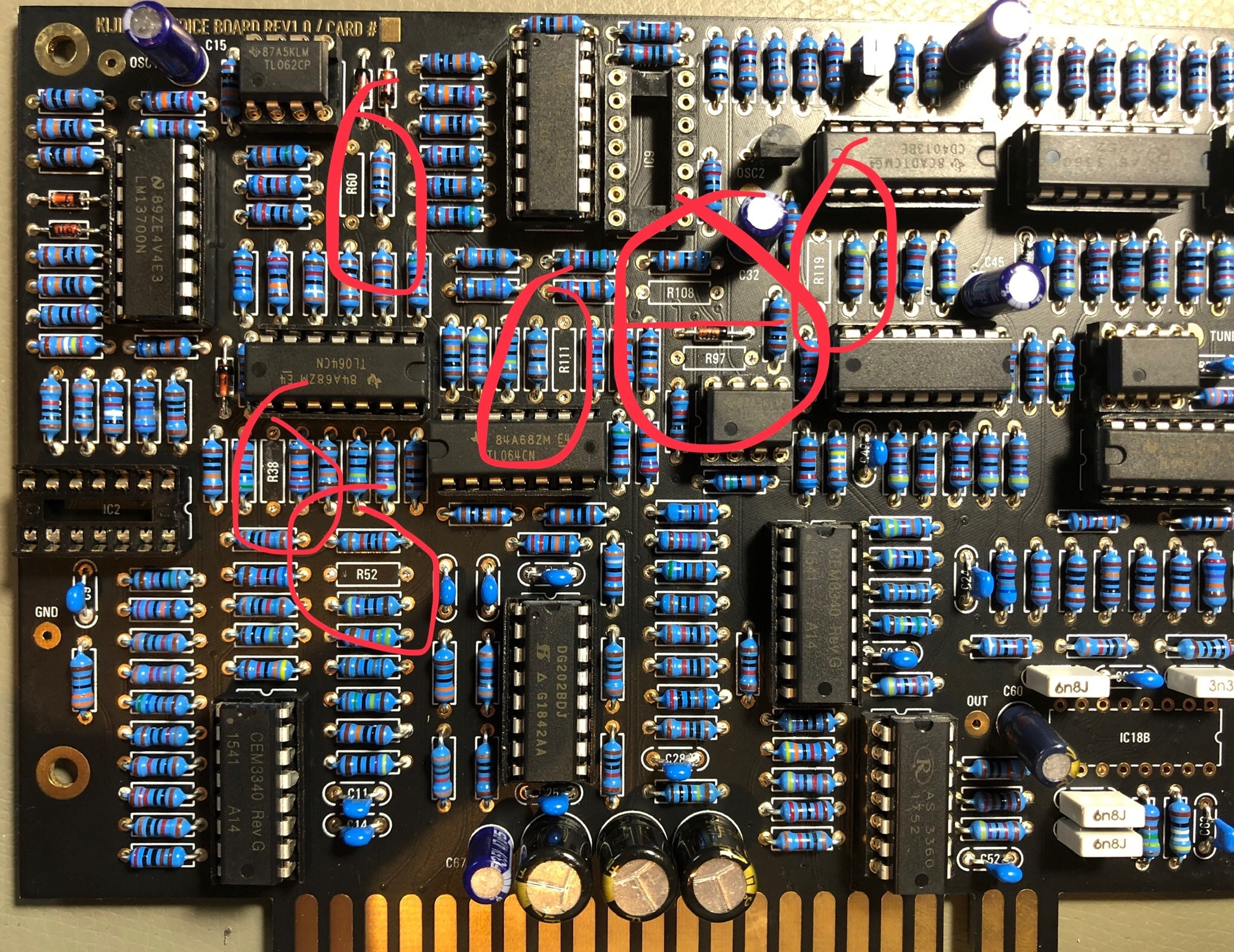
Voicecard:
replace R108 from 10K to 20K
replace R111, R52 from 91K to 20K
replace R38, R97 from 330K to 576K (i used a 560K plus a 20K resistor in series which was measured to 575k (1% resistors) (only 576K when you want TL074 for IC2 and IC9 otherwise use 330k)
remove R60 , R119 (220R) → not installed
replace IC2 and IC9 from TL064 to TL074
picture source: Facebook Luther Stevebennett
click to enlarge:

Total costs of Material:
600€ plus VAT Mouser (€ incl.19% german VAT)
AS3360 100€
AS3340 80€
ssi2144 ICs (VCF) 55€
OLED 5€
Potentiometer - 35€
Knobs 25€
Noise IC 10€
IC Sockets 20€
XMOS Programmer 22€
metalparts 20€
EDGE card holder 10€
pcb/panel plus VAT 1200€
case: ca.250€
____
TOTAL around: 2530€
Don´t miss the frontpanel and case from DIYHUB http://siddarthianinnovations.bigcartel.com/
| Note |
|---|
please respect your local requirements/laws for a powersupply (110V AC/ 230V AC) and doublecheck the power input jack polarity (inside +) and the diameter of 2.1mm or 2.5mm of the plug/jack or you learn it in the hard way |
User Manual
moved to page: Manuals and Firmware
Powersuply Warning
don't mix the external PSU bricks or you destroy your Device.
The Kijimi use a 24V DC PSU
DDRM v1 DIY use a 12 DC PSU
DDRM v2 DIY use a 12V DC PSU
Display OLED
make sure your OLED folow this pinout VCC-GND-SCL-SDA, very often shows the shop the correct pinout but deliver another type.
AND short the pins on the display side (where the Frontpanel is) to prevent shorts to the Frontpanel.
if you cant source the correct display (pin) use restore legs and bend they - use cable shrink tube to protect this for shorts
User Manual
Kijimi-manual-Draft-Version.pdf (early draft)
Software/Firmware/Bootloader:
Black Corporation Firmware Updater.app.zip (only for updater not for first install) - do not work on Catalina
Kijimi Factory Presets MJ (1.2).syx (presets - transfer it with sysexlib. per KIjimis USB-Midi-interface)
Kijimi1.1.0.bin(only for updater not for first install)
kijimi_1.2_package_build_by_DSL-man.zip (includes latest Firmware and presets, Updatetool) NEW
| title | Chnagelog- click to expand |
|---|
Change log:
1. 16+ LFOs!In the previous update, the ability to adjust individual amounts for each destination was added. This was not enough for some of the researchers on our team. As a result, all destinations now have their own LFO with individual control over all LFO parameters (AMOUNT, RATE, ATTACK, DECAY, SHAPE, etc) / In the previous update, the ability to adjust individual amounts for each destination was added. To provide even further control over sound design, all destinations now have their own LFO with individual control over all LFO parameters (AMOUNT, RATE, ATTACK, DECAY, SHAPE, etc)
To activate, (SETTINGS->LFO->MOD MODE->INDIVIDUAL)
To operate, select destination mode (Positive, Negative, Bipolar). Long press (Press and hold for approximately 1.5 seconds) the destination selector until flashing. The LFO parameters to the flashing destination may be adjusted with information presented in the display.
Multiple destinations in one row may be selected in order to affect all of those destinations with shared values.
If multiple destinations in different rows are selected, parameters for destinations in the first row may be adjusted with the LFO1 controls and parameters for destinations in the second row may be adjusted with the LFO2 controls. In this case, both LFO1 and LFO2 settings will appear on the display.
Once LFO adjust mode is activated (flashing), other LFOs may be selected by selecting them with a regular non-long press. Additional LFOs may be grouped with an existing group by long pressing the new destination while the first group is flashing.
A quick press of a flashing destination will deactivate LFO adjust mode and return to destination toggle mode.
2. Arpeggiator
Toggle on/off by pressing SHIFT+K.T.
Initiate Hold (Latch) by pressing SHIFT+Key OFF
Toggle and Hold may also be selected in SETTINGS
2.1 Styles:
-UP - lowest to highest
-DOWN - highest to lowest
-UP DOWN - lowest to highest (played once) and back
-UP AND DOWN - lowest to highest, then highest to lowest
-PINKY UP - similar to UP with highest note played between other notes
-PINKY UP DOWN - similar to UP DOWN with highest note played between other notes
-THUMB UP - similar to UP with lowest note played between other notes
-THUMB UP DOWN - similar to UP DOWN with lowest note played between other notes
-PLAY ORDER - notes play in the order they are engaged
-CHORD - repeats chords
-RANDOM - Notes play randomly
-RANDOM ONCE - Notes play randomly without repeating until all notes have been played.
2.2 Rate
If the arpeggiator is not synced to MIDI or an LFO, speed may be selected in the menu.
Divisions range from 32/1 to 1/1.5
Sync to MIDI or LFO (sync with LFO works only if the LFO is in MONO mode)
2.3 Randomizer
Scale 1-24 transposes the note based on the sign setting.
Chance 0-100% determines the possibility of a random note being played.
Sign bi (bipolar), add (adds notes above), sub (adds notes below)
Scale determines the range of random semitones 1-12
2.4 Velocity
-ON/OFF (if velocity is off, it defaults to a value of 64, if on it can range from 1-128 determined by Target.
-Target 1-64 selects the range of values the velocity will randomly play.
+ a new bank by Richard Devine!
make sure you perform the calibration of the knobs again as described (Potentiometer Calibration : Important: turn all pots to the right side (max) then only turn the center detent knobs to middle position for the center detent calibration. for the second step turn all knobs to right (max) position
Updater App Instructions:
Kijimi FW Updating instructions.pdf
OSX/macOS Installation of the Bootloader for the Kijimi DIY Version:
you need both files: (boot loader and Firmware)
Download for (OSX) XMOS TIME COMPOSER and copy it to you Application folder.
Install JAVA 6 from:
https://support.apple.com/kb/DL1572?locale=de_DE
turn the power off , install the xmas programmer in the IDC Socket, connect a USB cable to the xmas programmer, then:
OSX how-to
1. Open terminal
2. Type cd /Applications/XMOS_xTIMEcomposer_Community_14.3.3/
3. Press enter
4. Type
| Code Block |
|---|
./SetEnv.command |
5. Press enter
6. Type cd /Path/to/fw/folder
7. Press enter
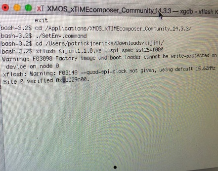
8. type
| Code Block |
|---|
xflash Kijimi1.1.0.xe --spi-spec sst25vf080 |
(power on Kijimi yet)
9. Press enter
10. wait - after 30seconds or one minute your terminal starts with same infos - ignore the first message (Warning: F0398 Factory...) see on bottom the picture.
message, after further seconds the terminal shows you some memory addresses which are written, and then: finished successfully, on the KIJIMI the OLED Display must show you some graphics (PNL mode etc)
Here´s a Video from me about the Firmware Installation:
| Widget Connector | ||
|---|---|---|
|
Microsoft Windows 7/10 howto intall the "bootloader/Firmware": (credits to Konrad K'sadhu Zientara)
In order to do that, one needs the XMOS's xTIMEcomposer utility bundle and Java 6 32bit.
steps: (after you have installed the xmos timecomposer on your PC)
1 - turn Kijimi power OFF
2 - plug the programmer into Kijimi
3 - connect the programmer to the PC via USB
4 - open a windows powershell (console/terminal) and type:
| Code Block |
|---|
xTIMEcomposer |
in the command prompt (this runs SetEnv.bin in the command line terminal. If You experience problems go to the xmos folder to locate the file and run it. >see Image)
the setenv command sets the Environment for the Java process/applications (the path of your Java and more)
5 - go to the folder, where the Kijimi firmware and flash setup files are located. (with the cd command like: cd C:\Users\patrick\Downloads\kijimi) or as shown in the bottom screenshot
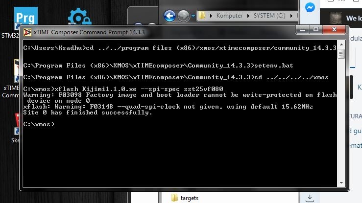
6 - type in the powershell:
| Code Block |
|---|
xflash Kijimi1.1.0.xe --spi-spec sst25vf080 |
7 - power ON the Kijimi
8 - the programmer will be disconnected for a while by the program
9 - the programmer will be reconnected and more LEDs will light up.
10 - there will be 2 error messages displayed in the terminal (F03098 and F03148 >see image) - ignore it
11 - adresses will show in terminal as being written into
12 - "finished successfully"
13 - the Kijimi will display it's menu on the OLED display
14 - turn OFF the Kijimi
15 - disconnect the programmer
DONE
Now the Kijimi is programmed and ready for calibration.
Calibration
everything is available in the software menu
- Potentiometer Calibration : Important: turn all pots to the right side (max) then only turn the center detent knobs to middle position for the center detent calibration. for the second step turn all knobs to right (max) position
- set the Voicecard amount to the value what you have installed
- set the Midi Settings to MPE or CP etc. (Channel pressure for standard keyboards)
- calibrate OSC 1 ..2 ..3...
- calibrate VCF
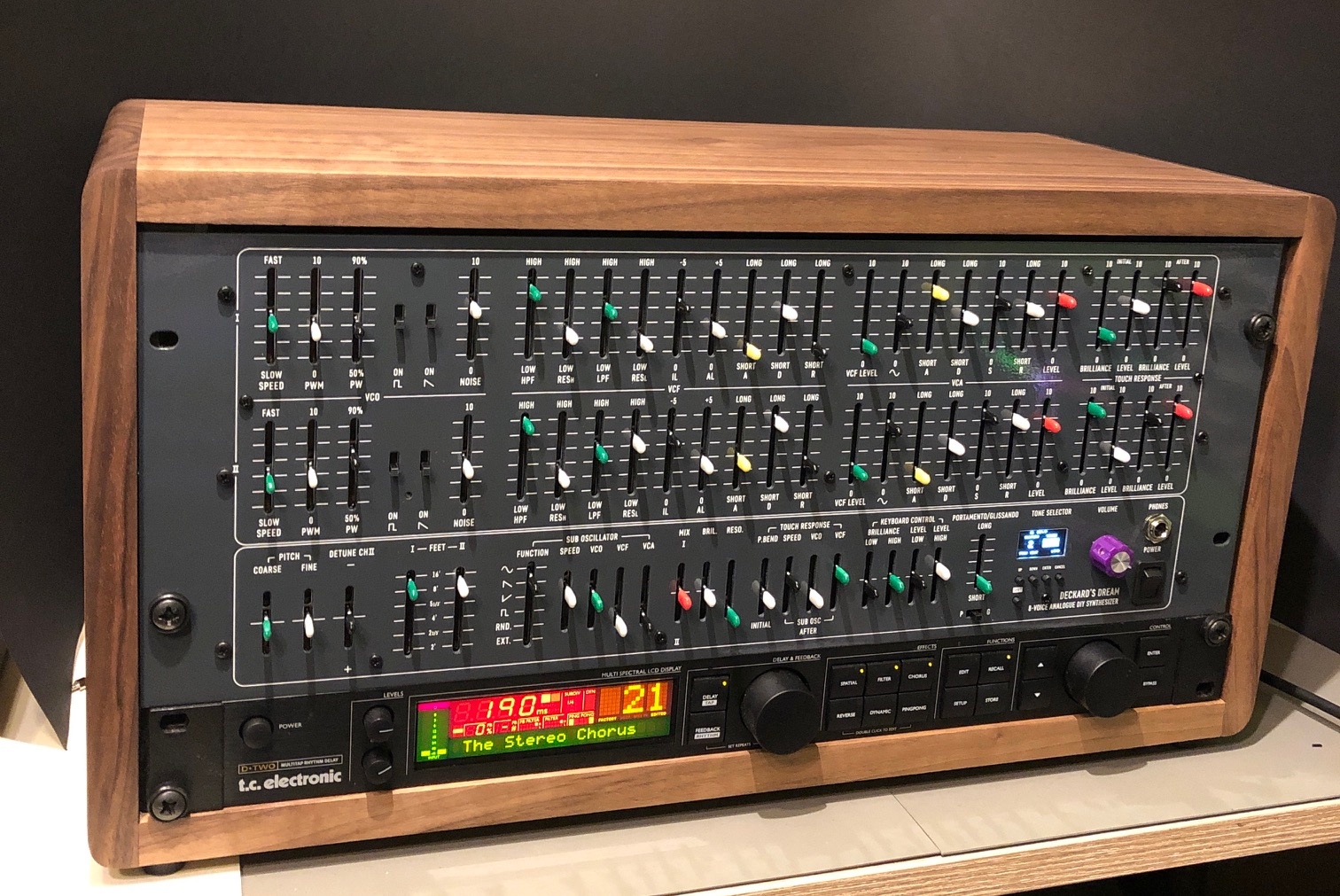
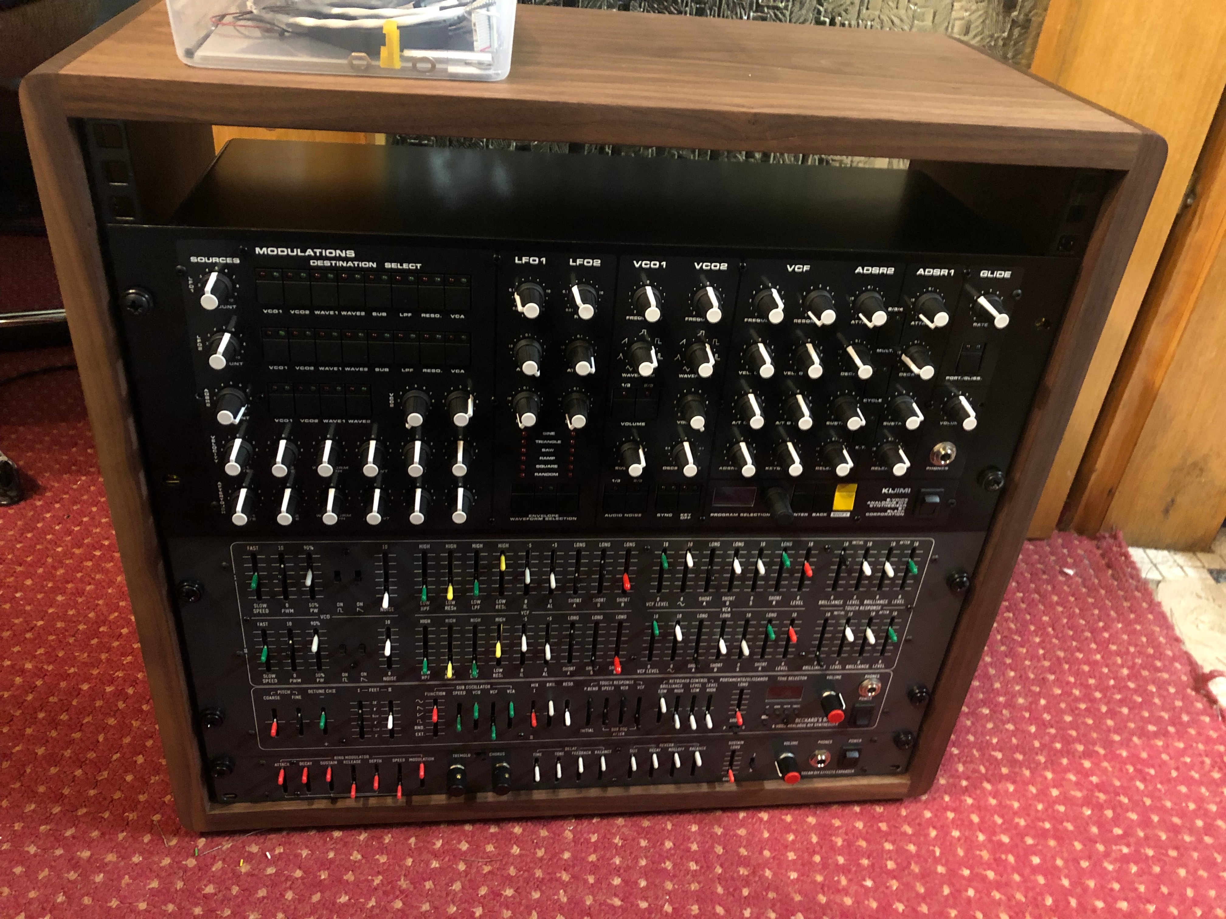
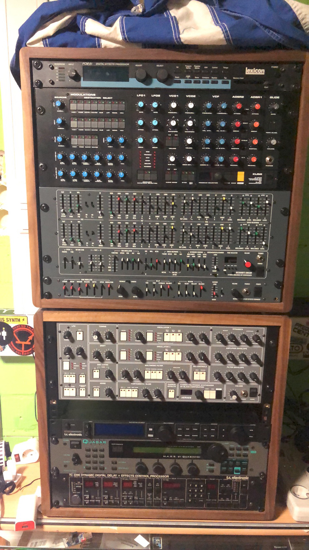
Wooden Case (same as in DDRM project)
ask me if you want a wooden case -walnut, oak .. whatever you want
please note, the case can ordered in different HE, order 5HE to include a effect device or expander (an expander isn´t confirmed yet)
| Gallery | ||||
|---|---|---|---|---|
|
Search this documentation
| Livesearch | ||
|---|---|---|
|
Popular Topics
| Popular Labels | ||||
|---|---|---|---|---|
|
Featured Pages
| Content by Label | ||||||||||||||
|---|---|---|---|---|---|---|---|---|---|---|---|---|---|---|
|
Recently Updated Pages
| Recently Updated | ||||||||
|---|---|---|---|---|---|---|---|---|
|