Page Contents:
That’s not an official guide.
It’s more an best practice guide, you find infos about the firmware/software on the main page: KIJIMI Documentation
- Sourcing parts, order higher quantities to get the best price and more parts for free or for a better condition than ordering later single parts and you have spares (tactile switch, encoder, potentiometer, opamps 3340,3360)
- Sort all parts, one carton with resistors, one for capacitors...one for mechanical parts, one for Ics/semis.
- Sort the values like 1R-999R, 1K-9.9K, 10K-99K.... same for capacitors
- Start with the mainboard and hardwareboard and next Breakoutboard and PSU.. so you left less plastic bags for the voices which makes things easier
- Use lead based solder core or you get trouble with the ground pads and in case of failure or wrong part placements it’s more complicated to desolder the part.
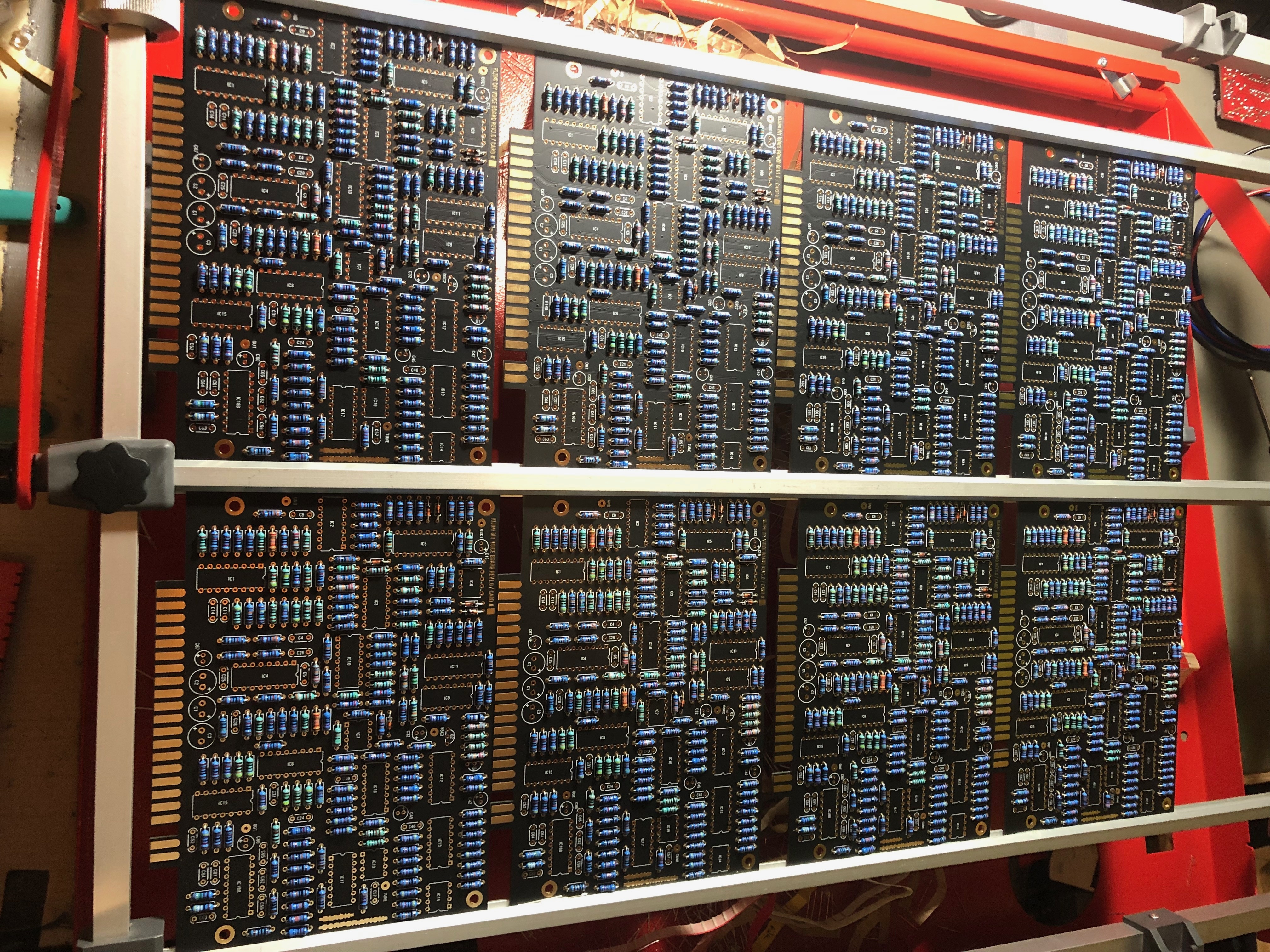
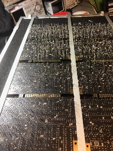
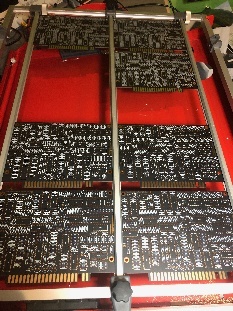
- Use for the voice cards a mounting frame which costs 50-250€.
Important
You have to respect the Known Issues/current Error List on this page - when you build an Kijimi, install at the beginning the Sub Osc Fix - and fill the holes of the resistors which you don't need anymore or use an edding pen and strikethrough the resistor numbers on the pcb.
BOM:
new BOM from July 2019 with improved Sound, i renamed the File because Roman used the same Filename as before which can confuse and ends in mistakes when you open accidentally an older file with same name.
BOM from 23.July 2019
KIJIMI-BOM-REV1.01_DSLMANxlsx.xlsx
please add 16x 1M resistors for the SUB OSC FIX
the Difference between first (v1.02) and latest BOM (xxx_DSLmanxlsx.) which improve the sound:
MOUSER Basket: (imported from above xls) (updated 28.May 05:40PM GMT+1) updated see issue list 1.June.2019 this BOM doesnt match with the SUB OSC fix and addional Panned Voice Outputs (there´s a separate Mouser project for the MOD)
https://www.mouser.com/ProjectManager/ProjectDetail.aspx?AccessID=6285be713e
the mouser project was improved for more parts - same price, the quantity is noted as "customer note" on each bag.
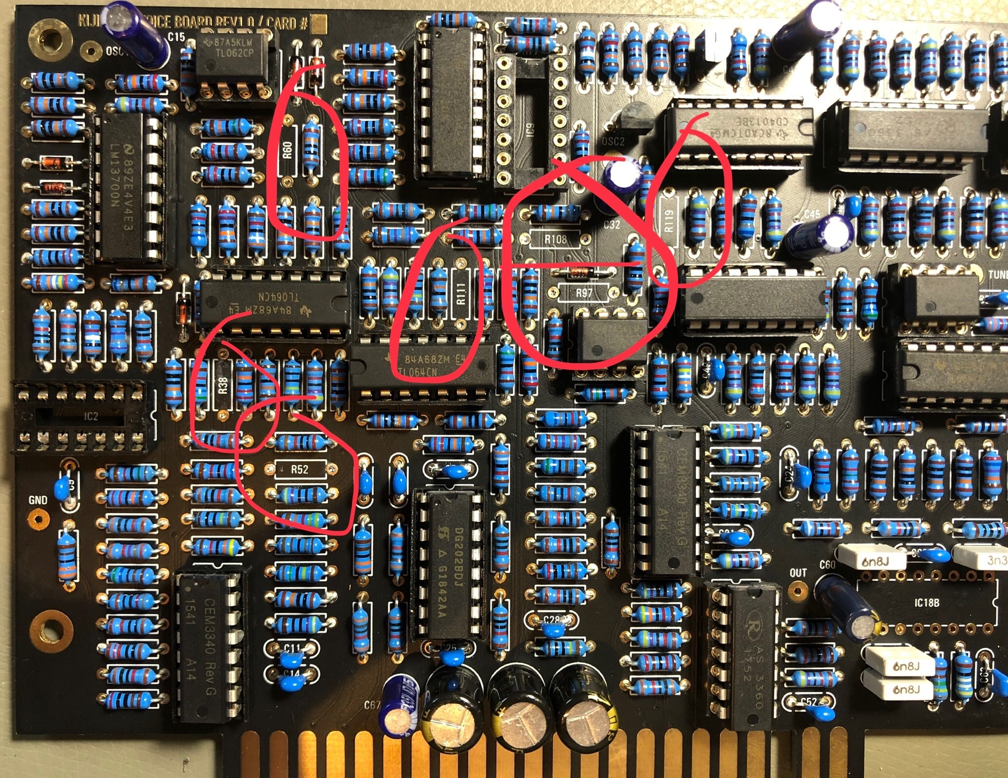
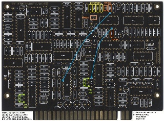
Voicecard change - must be used in your build !
replace R108 from 10K to 20K
replace R111, R52 from 91K to 20K
replace R38, R97 from 330K to 576K (i used a 560K plus a 20K resistor in series which was measured to 575k (1% resistors) (only 576K when you want TL074 for IC2 and IC9 otherwise use 330k)
remove R60 , R119 (220R) → not installed
replace IC2 and IC9 from TL064 to TL074
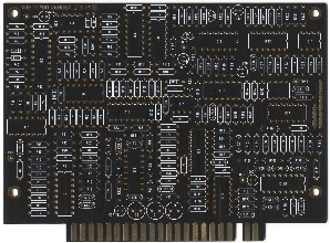
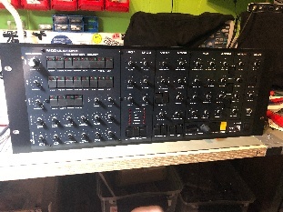
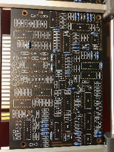
picture source: Facebook Luther Stevebennett
click to enlarge - this picture doesn't include the Sub OSC Fix !!!

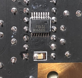
VOICE BOM ssi2140 Version
please note, this BOM only contains the the new ssi2140 Voicecard PCB parts
Mouser BOM: https://www.mouser.com/ProjectManager/ProjectDetail.aspx?AccessID=c757799ef6
(without ssi2140,AS3360,AS3340 available from: http://www.soundsemiconductor.com/buy.html
Attention
you have to change on the Mainboard one resistor as described in the above KIJIMI-VOICE-BOM-REV2.
this change the output Gain - the new cards are quiter than the old ssi2144 cards.
C61 on the Voicecard is 1nF film instead of C62
Total costs of Material:
Don´t miss the Frontpanel and case from DIYHUB http://siddarthianinnovations.bigcartel.com/
please respect your local requirements/laws for a powersupply (110V AC/ 230V AC) and
doublecheck the power input jack polarity (inside +) and
the diameter of 2.1mm or 2.5mm of the plug/jack or you learn it in the hard way ![]()
Modification
check out this page Kijimi Modifications
Powersuply Warning
don't mix the external PSU bricks or you destroy your Device.
The Kijimi use a 24V DC PSU
DDRM v1 DIY use a 12V DC PSU
DDRM v2 DIY use a 12V DC PSU
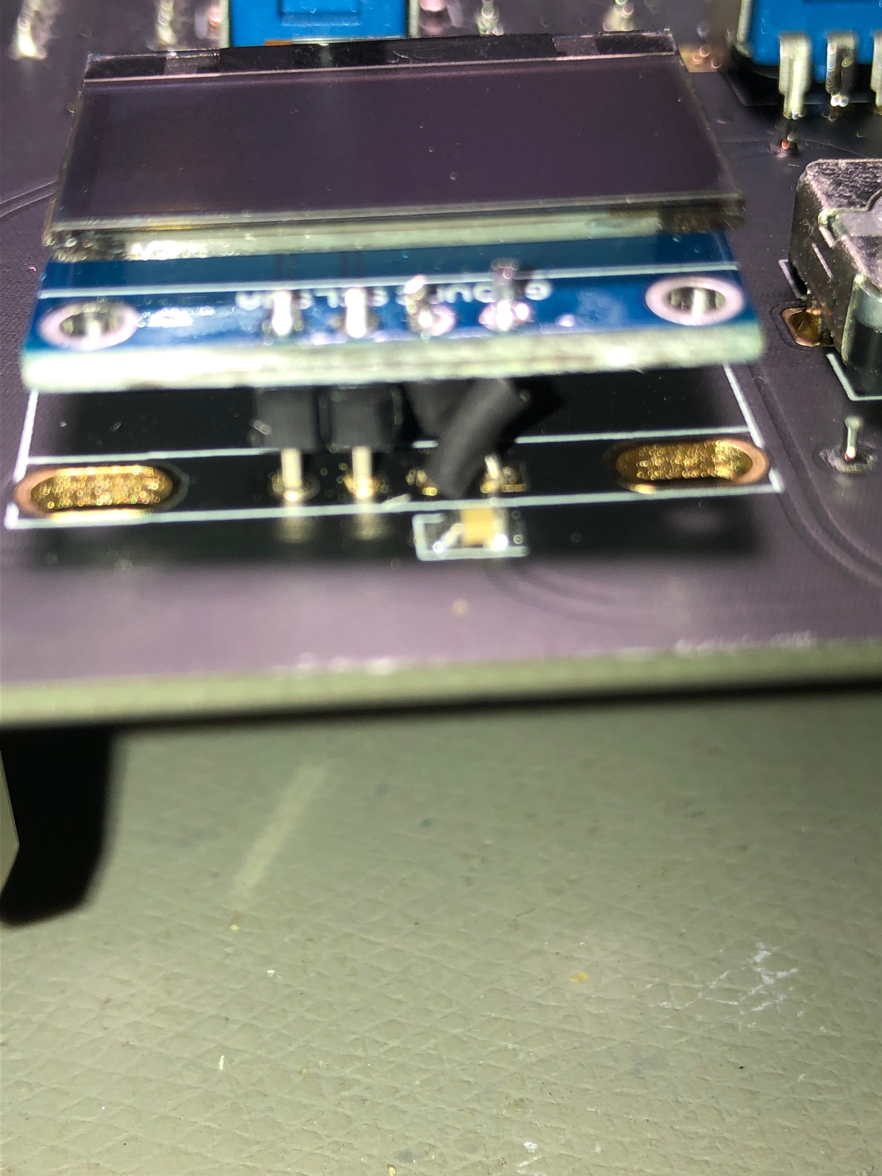
Display OLED
make sure your OLED folow this pinout VCC-GND-SCL-SDA, very often shows the shop the correct pinout but deliver another type.
AND short the pins on the display side (where the Frontpanel is) to prevent shorts to the Frontpanel.
if you cant source the correct display (pin) use restore legs and bend they - use cable shrink tube to protect this for shorts
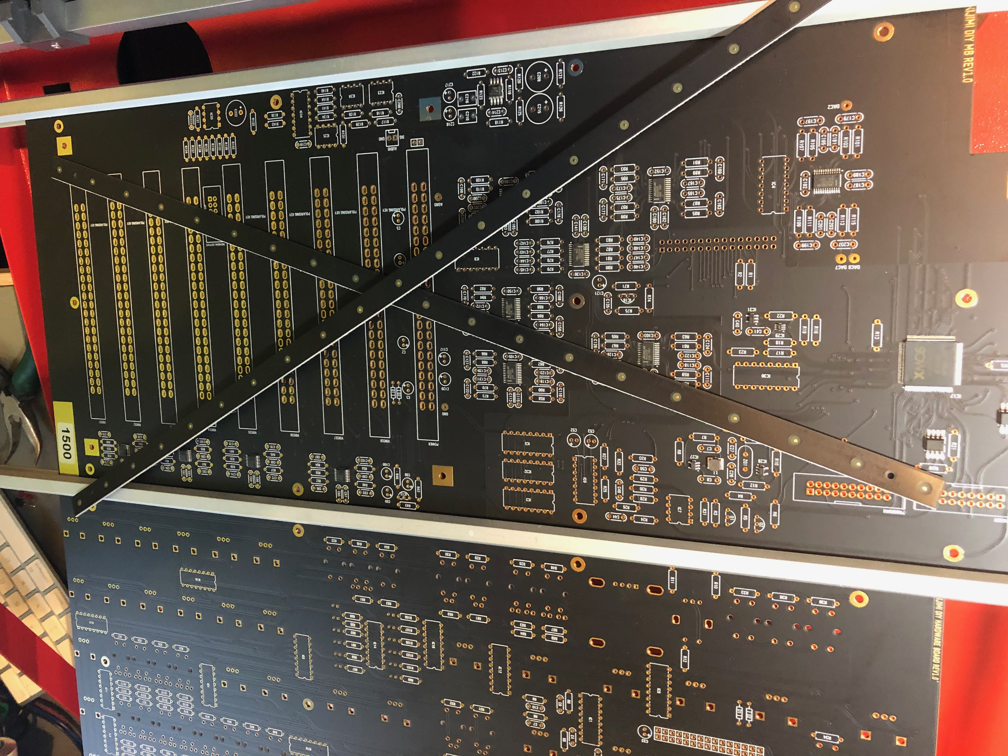
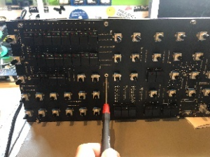
before you start, drill the 4 holes of the Mainboard to 4mm - that the mounting brackets can be attached with the supplied mouser screws.

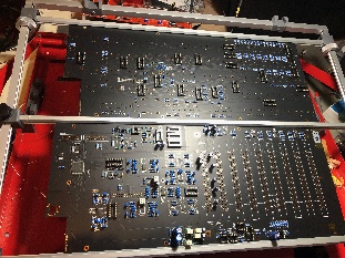
Hardwareboard (often called Mainboard by me) and Controlboard
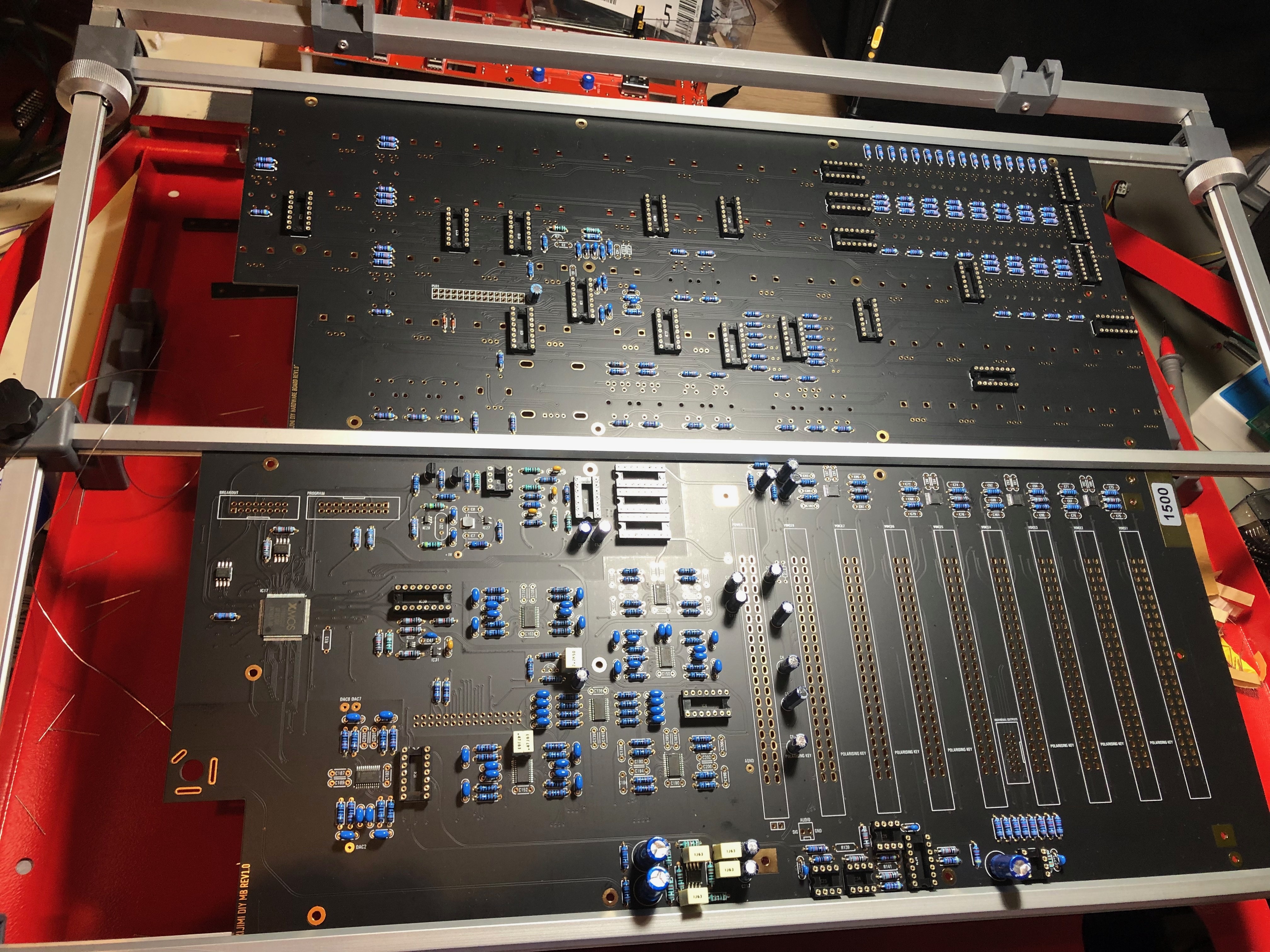
remove the PCB production (panelizing) stripes
100K resistors

all resistors (the change from the lastest BOM wasn't included here)
Dont install the IC socket on the location where you find on the nearside the SMT IC !! this socket isn't needed and its easier while soldering the SMT IC.
remove the panellising pcb parts from the mainboard/controlboard or it will not fit in the case later. (use a pliers and bend it carefully step by step)
Controlboard Infos
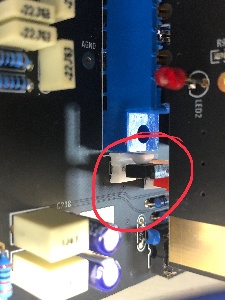
The front panel distance to the controlboard is 6mm, use a 5mm spacer and a washer or you can also use 6mm, 12mm Spacers between mainboard and Controlboard.
At this hole : DO NOT mount at the rearside a 12mm spacer, only use at top side a 5-6mm spacer and from rear a screw/nut (depends on what you have on hand) otherwise a 12mm spacer will short the voice card slot pins

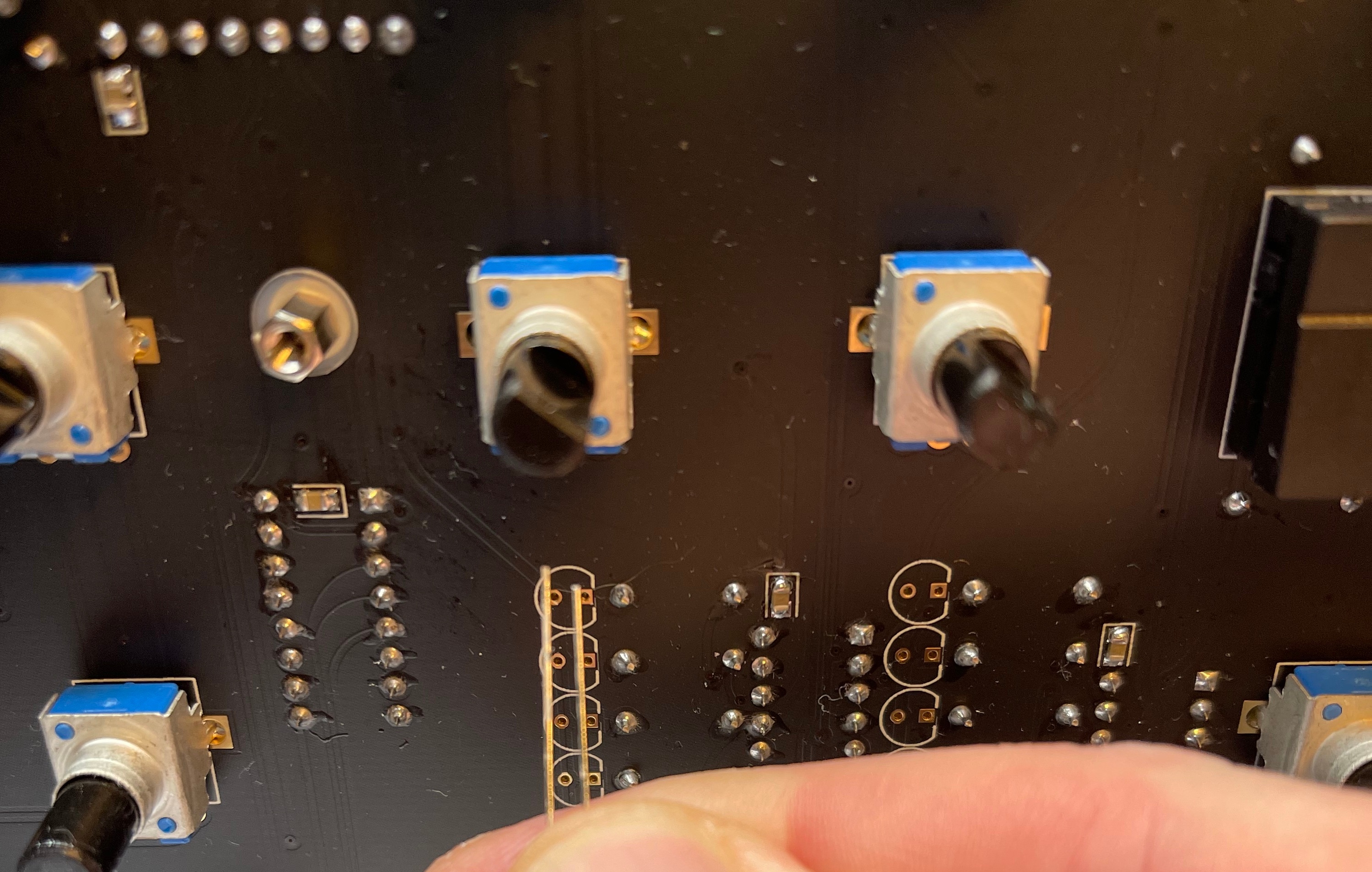
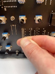
POTENTIOMETER:
install all potis and solder only one pin, then check the orientation of all pots in a row - maybe you have to change the alignment.. solder a groundpad and check the orientation again.
DISPLAY, make sure your pinout is correct - VCC-GND-SCL-SDA ! otherwise bend the 2 pins as shown in the picture and use shrink tube, double check it for shorts - or your 3.3V rail will be destroyed
dont install 5mm spacer between the display and PCB - you only need 3-4mm.. wait with the display until you have the front panel..
when you have the front panel: install all pots and all switches, put the OLED as shown in the place (dont solder it yet), put the front panel on the controlboard, fix the panel with screws,
the front panel must be in the same height as the switches or use washers/remove the washer to get the correct height. if everything is ok - solder the display at the outer pins and check the orientation again.
The Software/Firmware Installation process is described on the Mainpage
Current identified Errors/Omissions/Errata:
Date | Location | Identified Issue | Resolution | update |
|---|---|---|---|---|
| May 29, 2018 | BOM hw board | R119, R120, R121 not in BOm 1.02 | R119 4K7 R120 100R R121 2K2 | BOM project updated-1June2019 |
| May2019 | OLED DISPLAY major | Double check the OLED pinout | rin case of wrong pinout - remove 2 oled pinheader pins and use a resistor leg and cable tube shrink correct is: VCC-GND-SCL-SDA | |
| BAT43 x2 missing D3 D4 on Harware board | BOM project updated-1June2019 | |||
| 12 Jun2019 | BOM hw board | C34 missing in BOM | 560pf mlcc RM5 | |
| 30 July 2019 | Controlboard | dont install a Metal spacer between controlboard and mainboard in the middle of the pcb - otherwise it touch the card slot adapter pins
| use only the short 7mm spacer and a screw/nut from rear. | |
| 30 July | Audio output | install on both locations a 2pin header if you use the flat ribbon cable for the audio signal you have to bridge the pins with a jumper. when you use the MTA100 headers with coax cable, dont install the jumpers ! Connect only at the mainboard side (MTA100 header)the ground of your shielded cable. Don’t connect the GND at the MTA100 header at the breakoutboard or you get a groundloop (more noise, risk of hum) |
| |
| 30 July 2019 | info | use a 24V Center positive Powersupply with 2Ampere or more | don't use the 12V PSU from DDRM DIY Version. | |
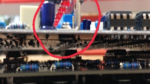
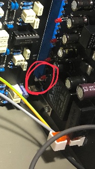
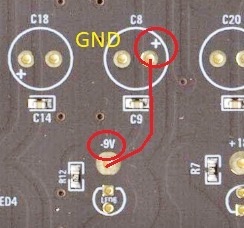
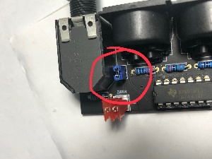
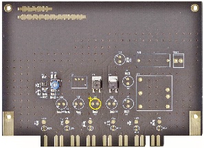
| 1 Aug 2019 | major bug | on the PSU card is the -9V Capacitor silkscreen wrong, this was happen on my PSU card and the capacitor leaked, thx to Ando for the picture. | install the positive pin of C8 on the left side (as shown in the bottom picture)
| reported to Roman and Bob |
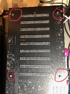
| 15 Aug. 2019 | mainboard | mounting holes for brackets do not fit with the Mouser screws. carefully drill a bigger hole as shown here: (marked) only this 4 holes |
| |
| 15 Aug | PSU | the fuse must be around 1.2Ampere, the current of the kijimi on 24V DC is 950mA | ||
August 2019 Major BUG | Voices | improve the sound (from Roman.F - the developer) | Voicecard: replace R108 from 10K to 20K replace R111, R52 from 91K to 20K replace R38, R97 from 330K to 576K (i used a 560K plus a 20K resistor in series which was measured to 575k (1% resistors) (only 576K when you want TL074 for IC2 and IC9 otherwise use 330k) remove R60 , R119 (220R) → not installed replace IC2 and IC9 from TL064 to TL074 | |
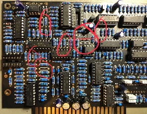
January 2020 Major BUG | Voices | fix the Subosc. Problem (glitches and artifacts) | Here is the SUBOSC fix Janne and I worked out. Details below: the addional parts are not included in the BOM (16x 1M resistor) (click to enlarge)
1. Remove these components: Q1, Q2, R126, R139 2. Add two 1M resistors as shown (to PCB solder side) 3. Add two jumper wires as shown (to PCB solder side) 4. R131, R133, R146, and R149 are not needed. If you already have them installed, no need to remove them (they don't do anything). If you are starting to build, don't install them. NOTES: This fix is for DIY REV1 KIJIMI only. Prebuilt Kijimi does not have this issue. You can omit all these highlighted parts and test your voice card without the SUBOSC feature. Everything else should still work. When modifying your voice card, do the modification on one card first and then test for any glitches (there shouldn't be any). Then modify the others. Please report back if you have any issues. Thanks to Janne for the hard work in helping to test and develop this fix. Technically this mod disconnects the saw waveform and routes the pulse waveform instead into the 4013 divider. The 1M resistors enhance the rise and fall time of the pulse waveform. The original problem was caused by transient noise on the saw waveform that triggered the 4013 divider. | thanks to Janne and Ando |
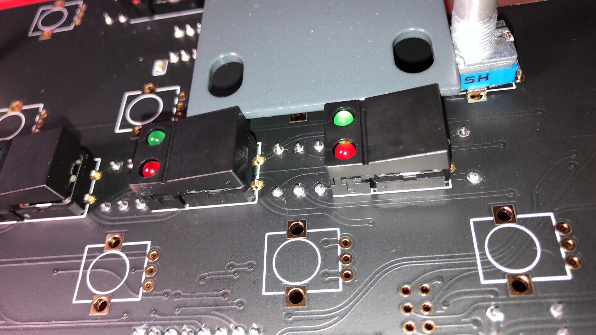
| December2021 | LED orientation for the mouser BOM LEDs |
|
Bootloader:
(the Firmware is on a other page to minimize confusion by rebuild Owners) : Manuals and Firmware
you need both files: (boot loader and the "DIY" Firmware)
Download for (OSX) XMOS TIME COMPOSER and copy it to you Application folder.
Install JAVA 6 from:
https://support.apple.com/kb/DL1572?locale=de_DE
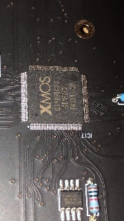
turn the power off , install the xmas programmer in the IDC Socket, connect a USB cable to the xmas programmer, then:
OSX how-to
1. Open terminal
2. Type cd /Applications/XMOS_xTIMEcomposer_Community_14.3.3/
3. Press enter
4. Type
./SetEnv.command
5. Press enter
6. Type cd /Path/to/fw/folder
7. Press enter
8. type
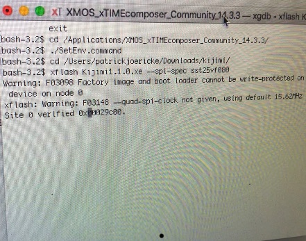
xflash Kijimi1.1.0.xe --spi-spec sst25vf080
(power on Kijimi yet)
9. Press enter
10. wait - after 30seconds or one minute your terminal starts with same infos - ignore the first message (Warning: F0398 Factory...) see on bottom the picture.
message, after further seconds the terminal shows you some memory addresses which are written, and then: finished successfully, on the KIJIMI the OLED Display must show you some graphics (PNL mode etc)
Here´s a Video from me about the Firmware Installation:
Microsoft Windows 7/10 howto intall the "bootloader/Firmware": (credits to Konrad K'sadhu Zientara)
In order to do that, one needs the XMOS's xTIMEcomposer utility bundle and Java 6 32bit.
steps: (after you have installed the xmos timecomposer on your PC)
1 - turn Kijimi power OFF
2 - plug the programmer into Kijimi
3 - connect the programmer to the PC via USB
4 - open a windows powershell (console/terminal) and type:
xTIMEcomposer
in the command prompt (this runs SetEnv.bin in the command line terminal. If You experience problems go to the xmos folder to locate the file and run it. >see Image)
the setenv command sets the Environment for the Java process/applications (the path of your Java and more)
5 - go to the folder, where the Kijimi firmware and flash setup files are located. (with the cd command like: cd C:\Users\patrick\Downloads\kijimi) or as shown in the bottom screenshot
6 - type in the powershell:
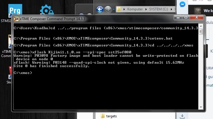
xflash Kijimi1.1.0.xe --spi-spec sst25vf080
7 - power ON the Kijimi
8 - the programmer will be disconnected for a while by the program
9 - the programmer will be reconnected and more LEDs will light up.
10 - there will be 2 error messages displayed in the terminal (F03098 and F03148 >see image) - ignore it
11 - adresses will show in terminal as being written into
12 - "finished successfully"
13 - the Kijimi will display it's menu on the OLED display
14 - turn OFF the Kijimi
15 - disconnect the programmer
DONE
Now the Kijimi is programmed and ready for calibration.
Calibration
everything is available in the software menu
- Potentiometer Calibration : Important: turn all pots to the right side (max) then only turn the center detent knobs to middle position for the center detent calibration. for the second step turn all knobs to right (max) position
- set the Voicecard amount to the value what you have installed
- set the Midi Settings to MPE or CP etc. (Channel pressure for standard keyboards)
- calibrate OSC 1 ..2 ..3...
- calibrate VCF
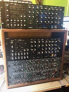
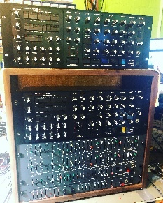
Gallery Kijimi |
|||
|---|---|---|---|

|
|
|
|

|
|
|

|
|
|
|

|
|
|
|
|
|
|
|
|
|
|
|
|
|
|
|
|
|

|
|
|
|
|
|
|
|
|

|

|
|
|
|
|
|
|
|
|
|

|
|
|