...
varislope_full_version_bom.pdf
Randomsource BOM:
VarSlopeFilter_RS_deluxe_BOM.pdf (blue = change for 12V) (purple =15V version)
Documents:
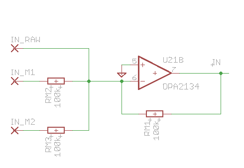
Input Mixer:
LFO Mod:

Output Buffer:

Component view:

Pots:
Input Level - Audio signal input level control
Feedback - Resonance Loop. Can burst into self-oscillation. Inverted or non-inverted feedback for unusual effects.
Mix - Wet / Dry mix of filtered and unfiltered signal. Inverted or non-inverted mix. Mandatory for phasing; interesting for LPF mode because of phase cancellation effects.
Ouput Level - Output attenuator for audio signal
APF / LPF - Switches to change the function of the 6 filter stages from All Pass Filter (Pole/Zero pairs) to Low Pass Filter (Poles only). 3 Switches for 3 pairs. (6 individual switches would be possible as well.)
Mix / Filter - In "Filter" position the "Mix" potentiometer is disconnected for 100% filter signal without any crosstalk from the dry signal (important for powefull 36dB/Oct LPF effect).
Clean / Dirty - Dirty applies some dynamic load to the single-ended buffer of the last filter stage.
Active / Bypass - True hard bypass
Slope - Spreads the pole frequencies of the individual stages. This means less filter steepness in LPF mode (ccw end is 36dB/Oct), and wider notch spacing in Phaser (APF) mode.
LFO Amount - Modulation amount of on-board LFO
LFO Wave - Crossfade between LFO waveshapes: Tringle -> Sine -> Square -> Sample&Hold -> Audio-Rate Self-Modulation (see video).
Also possible, but not on Front panel:
Slope Control Voltage Input
LFO Amount Control Voltage Input
LFO Waveshape Control Voltage Input
LFO Rate Control Voltage Input
External Filter or Phase Control Voltage Input (for ADSR etc.)
External 1V/Oct Control Voltage Input (no tempco, though.)
...