...
BOM: (not finally approved yet but I'm 85% sure it matches)
ISE-NIN-BOM-REV1.0.1.xlsx updated by BC on 24th.Sep.2022
ISE-NIN-BOM-REV1.0.1.pdf. updated by BC on 24th.Sep.2022
Issues: please wait with ordering parts or have a look at the ISSUE lists below for changes!!
...
Date | Location | Type | Identified issue | Resolution | related for development | affected PCB version | fixed Version | ||||
|---|---|---|---|---|---|---|---|---|---|---|---|
| 30 Aug. 2022 | BOM - Voices | ERROR | Mouser part number for the trimmer is invalid | Line 180: 652-3296X-1-103RLF | BOM 1.0.0 and 1.0.1 update needed | -- | |||||
| 30. Aug 2022 | BOM - Mainboard | INFO | the 220uF caps on the Mainboard are BI-POLAR - | respect the BOM partnumber | |||||||
| 07 Sep. 2022 | Hardware Board | BUG | there's no Pinout described on the Hardware Board for the OLED - | please read the INFO section in the next table on "OLED selection" carefully | can be improved with better silkscreen information | 1.0 | |||||
| 13 Sep. 2022 | BOM: Voices | INFO | the Mouser BOM shows 32x 240pF C0G capacitors for the Voices - used in the OTA Filter. These are 10% tolerance. | you can change the capacitors to Polypropylene, Silver MICA, Styrene - with 1-2.5% or match good capacitors in this range with an LCR meter (check the data sheets of the meter) | - | - | - | ||||
| 13.Sep | create a Silkscreen for MTA156 Powerheader pinout | 1.0 | 15.sep | bom MB | flash 2x delivered | check bom - patrick | |||||
Important Information before you start assembling:
...
Date | Location | Type | Issue | Tip | |
|---|---|---|---|---|---|
| 13. Aug.2022 | Hardware Board | INFO | minimize Slider/Potentiometer malfunctions Soldering Info | when you install the sliders, DO NOT solder all pins successively, solder only one pin at the top and the bottom and proceed to the next slider, when you have installed all of them - solder the next single pin of each slider. this has to be respected with potentiometers too. The Sliders and Potentiometers have lubrication inside which is sensitive to heat and can be easily damaged (this mistake was made in many Syncussion clones ) | |
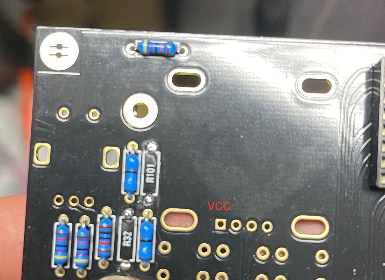
| 13. Aug.2022 | Hardware Board | INFO | OLED Selection and R101/R32 - R100/R102
| when you have an OLED with the PINOUT: VCC-GND-SCL-SDA install R100 and R102 (0 Ohm - a bridge) (R32/R101 must be left empty) in case you have an OLED with the PINOUT: GND-VCC-SCL-SDA install R101 and R32 (0 Ohm -a bridge) | |
| 13. Aug. 2022 | All pcbs | INFO | some IC Sockets do not point in the same direction as the others, it´s a known issue that people install ICs backwards | Double and triple check every IC orientation - maybe 80% of all device malfunctions happen because of that and often end in very expensive repairs | |
| 13. Aug.2022 | Hardware Board, PSU, Mainboard | INFO | the LEDs do not work | when you build the device - its important to start with the power supply - here you can test the LED orientation. never trust the vendor pinout for LEDs. normally the long LED leg is the positive end (anode) (but some circuits are powered from negative rails and GND is the positive end in this case- just as an explanation) | |
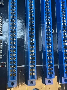
| 13. Aug. 2022 | Mainboard | INFO | solder the pins on the Edgecard holder where you find the white stripe on the PCB -
| you can't install the edge cards in the wrong way | |
| 14.Aug.2022 | Mainboard | INFO | keep the length of the power cable as short as possible - that minimizes the risk that you accidentally put the PSU card in a voice card slot | ||
| 14.Aug.2022 | Hardware Board | INFO | pay attention to "Pot23 - Volume" (upper right corner) this is the one non-center detent pot. | ||
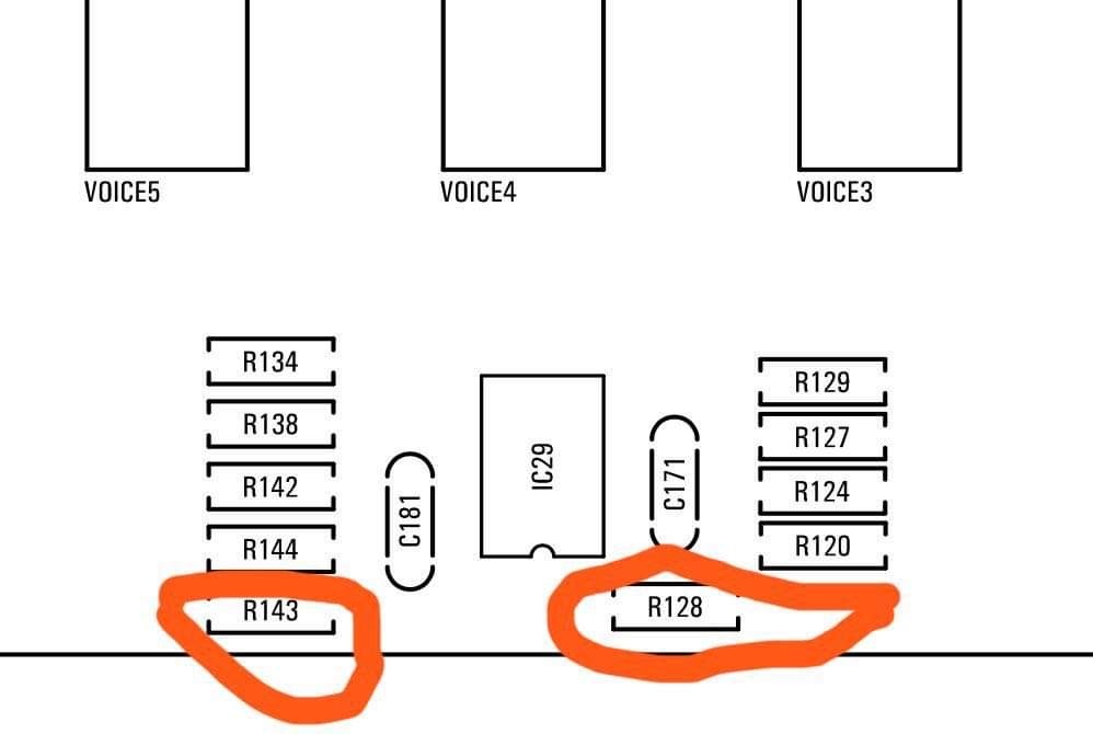
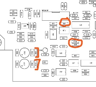
| 14.Aug.2022 | Mainboard | BUG | BOM1.0 Change- fixed in BOM v1.0.1 R103, R104, R105 = 330K (was 30k in BOM rev 1.0.0) R128, R143 = 10K (was 30k in BOM rev1.0.0) R137, R146 = 10K. (was 20k in BOM rev1.0.0)
| fixed on 24.Sep.2022 in BOM 1.0.1 |
Build guide: ( in progress)
...
Instructions for Calibrating
| Panel | ||
|---|---|---|
| ||
• First, put all CENTER DETENT pot / sliders at center, |
...
| Panel | ||
|---|---|---|
| ||
after 30 min of warmup |
...
go to the MENU, CALIBRATION, VCO CALIBRATION, press run. |
...
| Panel | ||
|---|---|---|
| ||
ATTENTION: this step must be improved !!!! use the workaround for now after above step - (the device must be have a 30min warmup)
Follow these steps from the Jupiter 8 manual, turning Trim1 for each voice (or see below):
Workaround or turn Trim TR1 until the self oscillation is off on each voice. you can switch between the cards using the switch button on the mother board. |
...
| Panel | ||
|---|---|---|
| ||
Go into MENU, FILTER, CALIBRATION, run |
...
Respect the Cross Mod TRIM vs Cross Mod Calibration - this steps must be in the correct procedure
| Panel | ||
|---|---|---|
| ||
MENU, CALIBRATION, CROSS MOD TRIM, connect USB out of ISENIN to computer, turn on ableton select ise-nin as input, put a tuner oh the channel and adjust it to 220hz for each voice, switch between voices with the switch button. |
...
| Panel | ||
|---|---|---|
| ||
Go into MENU, CALIBRATION, CROSS MOD CALIBRATION, press run |