...
Note the change of one value of resistor in the 218Hz filter. A 910k has been substituted for the original 470k.
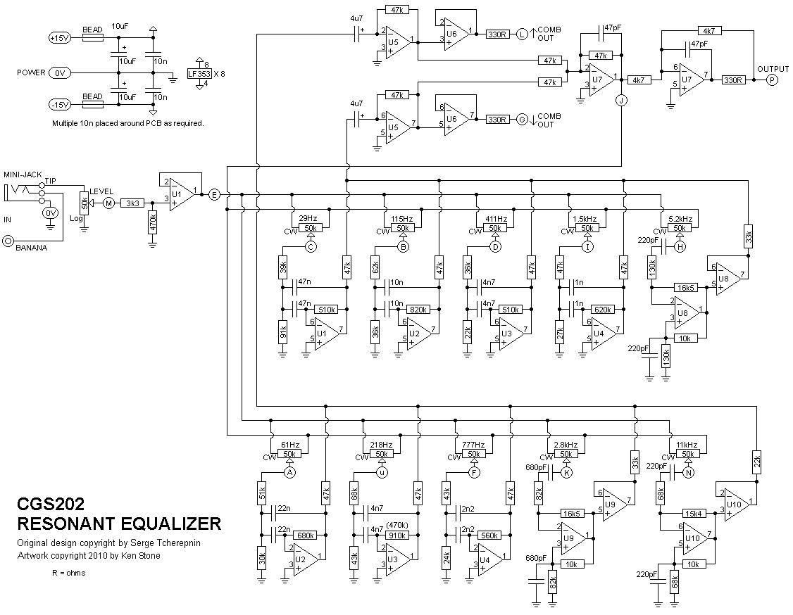

| The component overlay for the VER1.0 PCB. Click here for an enlarged, printable version. Print at 300dpi. Note the change of one value of resistor in the 218Hz filter. A 910k has been substituted for the original 470k. |
...
| A | 61 Hz pot Wiper |
| B | 115 Hz pot Wiper |
| C | 29 Hz pot Wiper |
| D | 411 Hz pot Wiper |
| E | to CW end of all filter pots |
| F | 777 Hz pot Wiper |
| G | lower comb out |
| H | 5.2 kHz pot Wiper |
| I | 1.5 kHz pot Wiper |
| j | to CCW end of all filter pots |
| K | 2.8 kHz pot Wiper |
| L | upper Comb out |
| M | input (to wiper of level pot) |
| N | 11 kHz pot Wiper |
| P | output |
| u | 218 Hz pot Wiper |
| X | +VE in |
| W | 0V in |
| Z | -VE in |
| 0V | 0V/GND connection for 3.5 or 6.5mm jacks and CCW end of level pot. |

Set Up
There is no setup required.
...
testing 0,5h (initial function 0,25h, longtesting burn in test 0,25h)
sum = arround 5,5h
| Gallery | |
|---|---|
|
|