...
validated ! works
Callibration
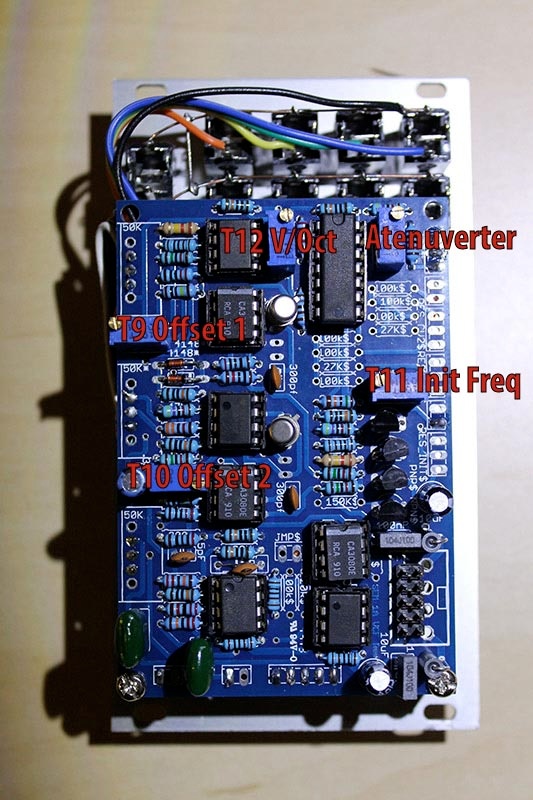
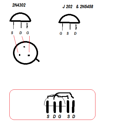
1) Using an oscilloscope, check pin Q8 on board -to-board connector (this pin is the nearest to connector I1).
2) Turn "Notch" pot to "HP".
3) Adjust "OFFSET 1" trimmer to zero volt.
4) Turn "Notch" pot to "LP".
5) Adjust "OFFSET 2" trimmer for zero volt.
6) Center VCO1 frequency pot and VCF frequency pot (at 12 o'clock).
7) Apply VCO1 pulse waveform into VCF and rotate resonance (Q) pot fully clockwise.
8) Adjust VCF "INIT FREQ" trimmer until fundamental (F1) is prominent.
9) Juper CV input to pin H1.
10) Depress key one octave above lowest keyboard key and adjust VCF "Volt/octave" trimmer for maximum signal.
11) Repeat steps 1 through 5..
...