...
- add both jumpers, kybdCV/GND and near the ferrite beads
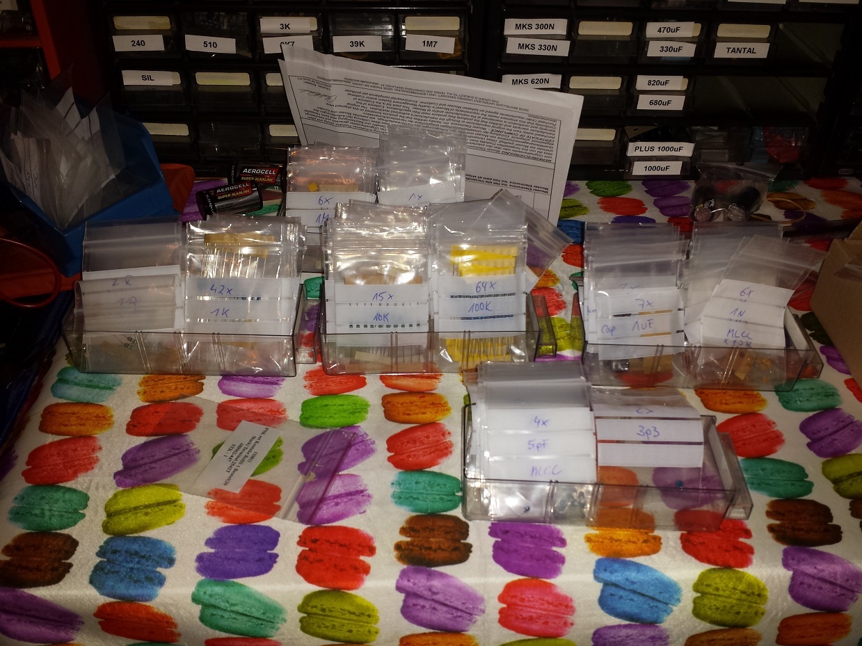
- sort out all resistors in values: 1R - 999R, 1K - 9K, 10K-99K, 100K-999K, 1M-22M , same with capaciators.
- take a label/sticker on places where you have MODS/bugfixes like c20 cap, noise mod etc..
- put the TTSH pcb on 25-30mm spacers (use the BD236/BD237 holes too for spacers) you have to mount a spacer on each side of the pcb so you can turn the pcb for soldering..
- build the complete VCO- Subboards (so you don't have to look for missing resistor points on the main pcb all the time)
- solder all IC sockets on both sides of the pcb (LED IC on the other side of the pcb)
- solder all voltage connectors (MTA´s) in the powersection, key cv, speaker etc.
- put all resistors in place on the main pcb, start with the highest amounts; (more than 60 x 100K) ... if you'll have completed nearly 80% and it'll be easier now to put the rest in place section by section.
- solder all resistors from the top
- turn pcb and cut all pins/legs - this way you can solder all pins/legs in one step..
- if you have a VCO voltage regulator from nordcore, put a tape over the 100nF/10uF caps near the power MTA header.
- Capaciators - begin with 100nF c0g for the audio path, followed by 100nF for the rest,and then all the other caps.. pay attention on the filmresistors... I use film caps (wima) for the VCF near matched trannys which makes the Filter sound really good.
- solder all caps from the front/rear.. keep attention on the C20 cap
- put all diodes and trannys in place ..(pay attention on c20, max noise fix, bridge instead of 2n5172 in clock, in VCF matched, sont mount the Amp. cooling blocks
- put all the LM301 in the IC-sockets
- build the VCO header connection for all 3 VCOs..
- unmount the 25-30mm spacers and replace them with the final 12mm spacers and screws..
- solder all faders, begin with 1 solderpoint on every side, put the frontpanel on the pcb and check the fader orientation. - alternative: bend one leg on each side and solder one point only
- check the orientaion
- finally solder all the faders..
- Jacks: solder on each corner 1-2 jacks, and 3 in middle, place the panel and then solder them
- then place all jacks, put the panel on top and mount the nuts on the jacks in the corners, then turn the panel, now you can solder all the jacks..
- switches.. unmount the panel, put all switches in place and mount the panel, turn the panel/pcb .. the switches fall in place, solder a bit.. turn the panel and check the orientation on the frontpanel, if it is good , solder finally ( please check the mechanical function of the switch before you mount them, sometimes you have faulty switches and its hard to desolder them..)
- *update 01.October 2014 : if you want to test the TTSH with speakers but without the headhone jack wiring add a jumper to TN/ T or RN/R otherwise your speaker won't work.
- build the power wiring cables and solder the internal DC-DC adapter..
- initial check : disconnect all sections, check the voltage near DC-DC adapter with a DMM .
- if you have a VCO regulator, build it, put it on the powerheader, drill a hole in the pcb and mount a spacer,calibrate the regulator to 14,6V
- test and calibrate the TTSH - good luck
...