...
you can also use 6mm Spacers on top of the Cntrolboard, 12mm Spacers between HWboard and Controlboard.
Current identified Errors/Omissions/Errata:
Date | Location | Identified Issue | Resolution | update |
|---|---|---|---|---|
| May 29, 2018 | BOM hw board | R119, R120, R121 not in BOm 1.02 | R119 4K7 R120 100R R121 2K2 | BOM project updated-1June2019 |
| May2019 | OLED DISPLAY | Double check the OLED pinout | rin case of wrong pinout - remove 2 oled pinheader puns and use a resistor leg and cable tube shrink | |
| BAT43 x2 missing D3 D4 on Harware board | BOM project updated-1June2019 | |||
| 12 Jun2019 | BOM hw board | C34 missing in BOM | 560pf mlcc RM5 | |
| 30 July 2019 | Controlboard | dont install a Metal spacer between controlboard and mainboard in the middle of the pcb - otherwise it touch the card slot adapter pins
| use only the short 7mm spacer and a screw/nut from rear. | |
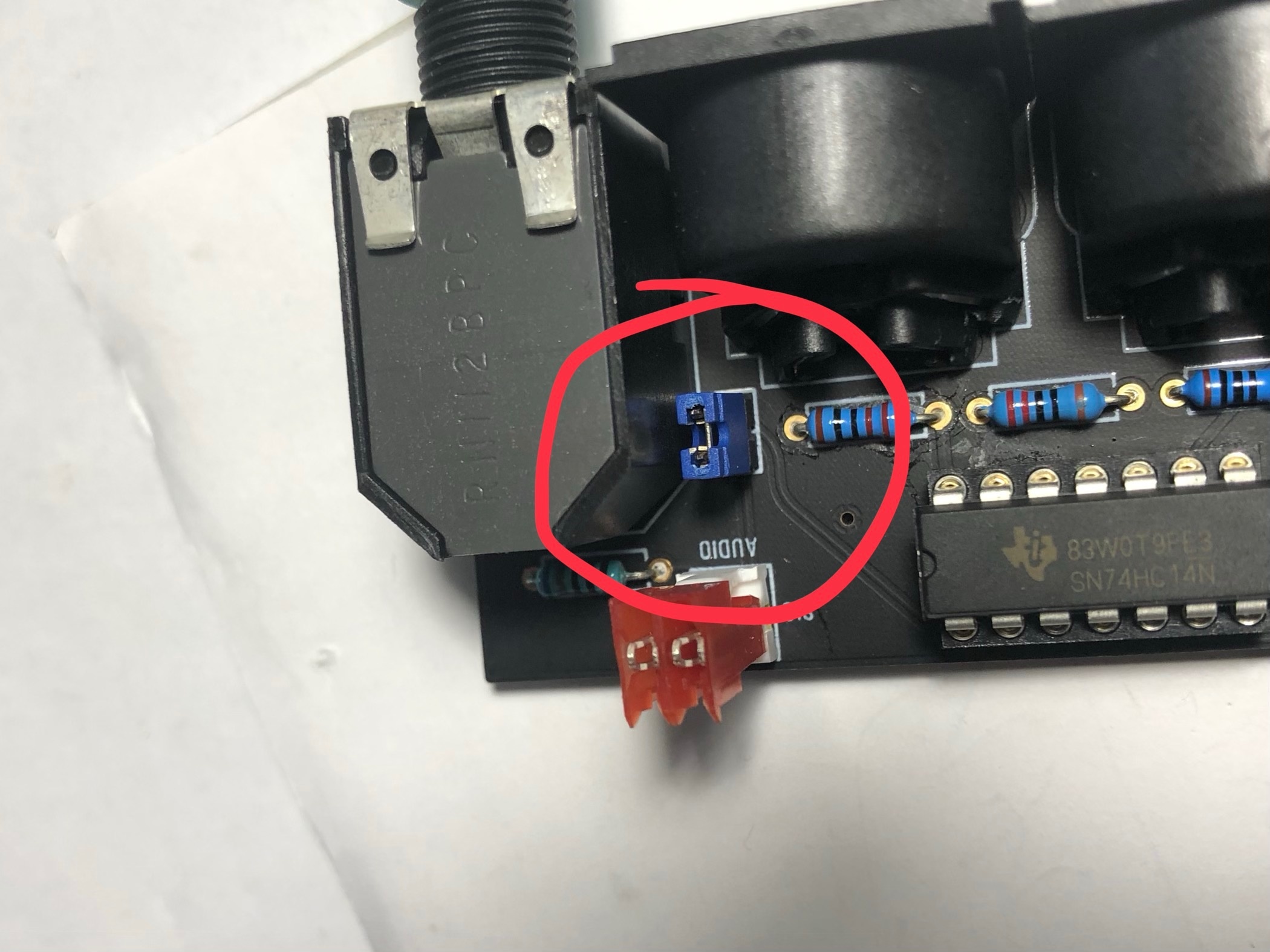
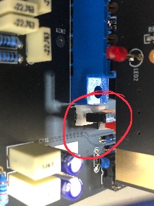
| 30 July | Audio output | install on both locations a jumper (bridge both pins) if you use the flat ribbon cable. when you use the MTA100 headers with coax cable, dont install the jumpers. |
| |
| 30 July 2019 | info | use a 24V Center positive Powersupply | don't use the 12V PSU from DDRM DIY Version. | |
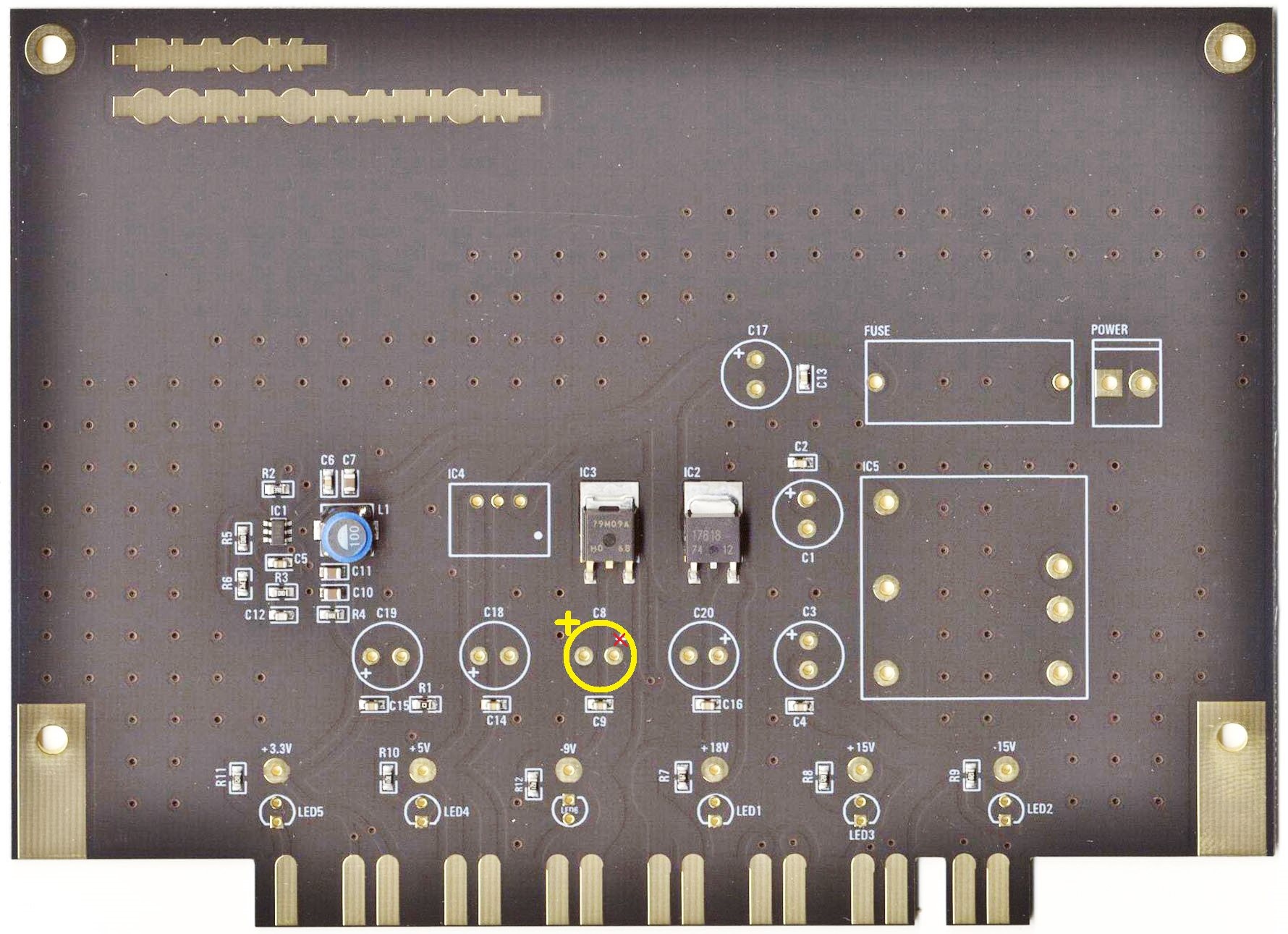
| 1 Aug 2019 | major bug | on the PSU card is the -9V Capacitor silkscreen wrong, this was happen on my PSU card and the capacitor leaked, thx to Ando for the picture. | install the positive pin of C8 on the left side (as shown in the bottom picture)
| reported to Roman and Bob |