...
| Info |
|---|
the KBD Out jack switch pin must be isolated from the pcb trace: (TTSH REV 2-3-4) 2 options are possible:
|
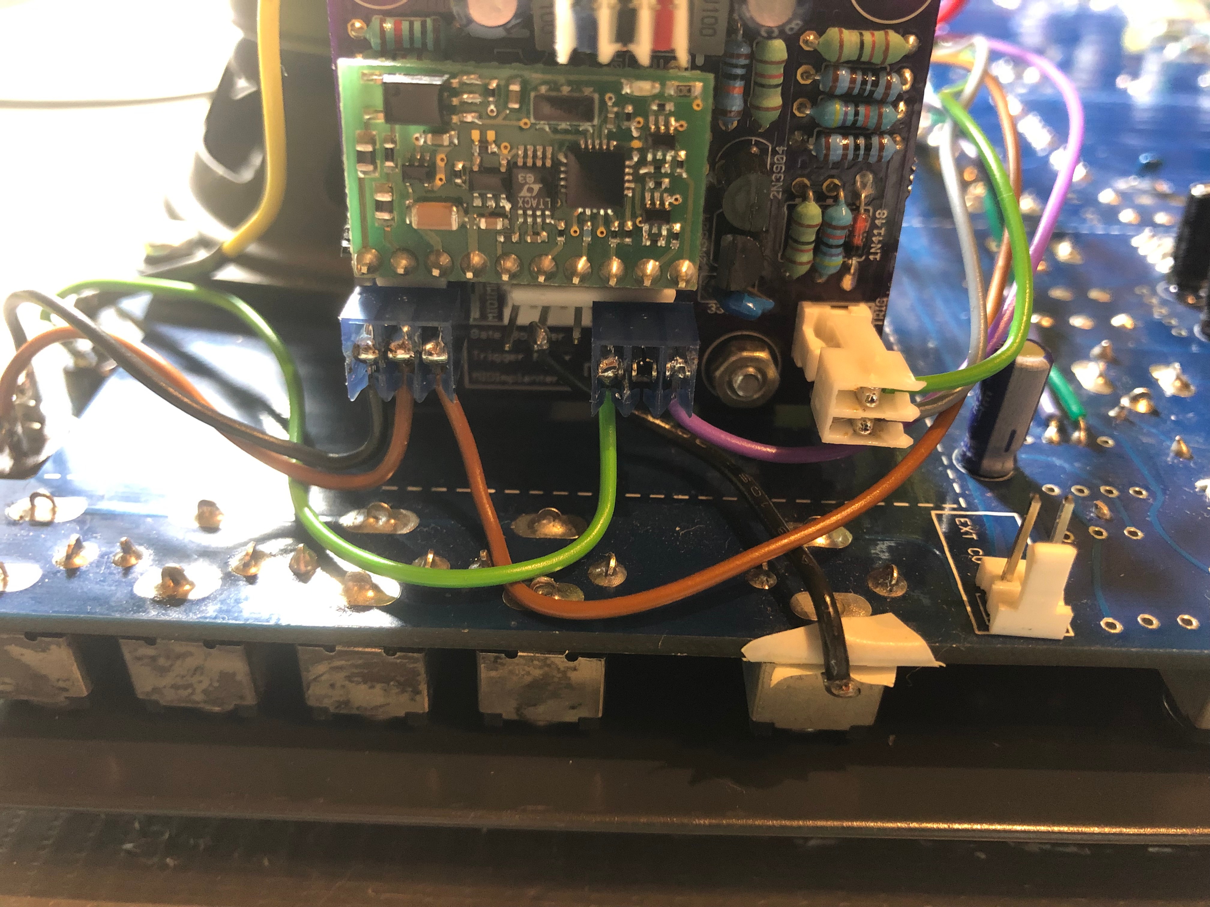
5. connect 3 cables to the GATE/S-H section (AR/ADSR)
the midiimplant gate out must be connected to the Gate jack (switch pin) the Gate jack tip must be connected to Gatebooster input (3pole header right pin)
you have to cut a trace (the trace between gate switch top pin to GATE input)
the gatebooster gate out is connected to the clock switch top left pin, the trigger is connected from gatebooster trigger out to the trigger pcb header (near s/h switch)
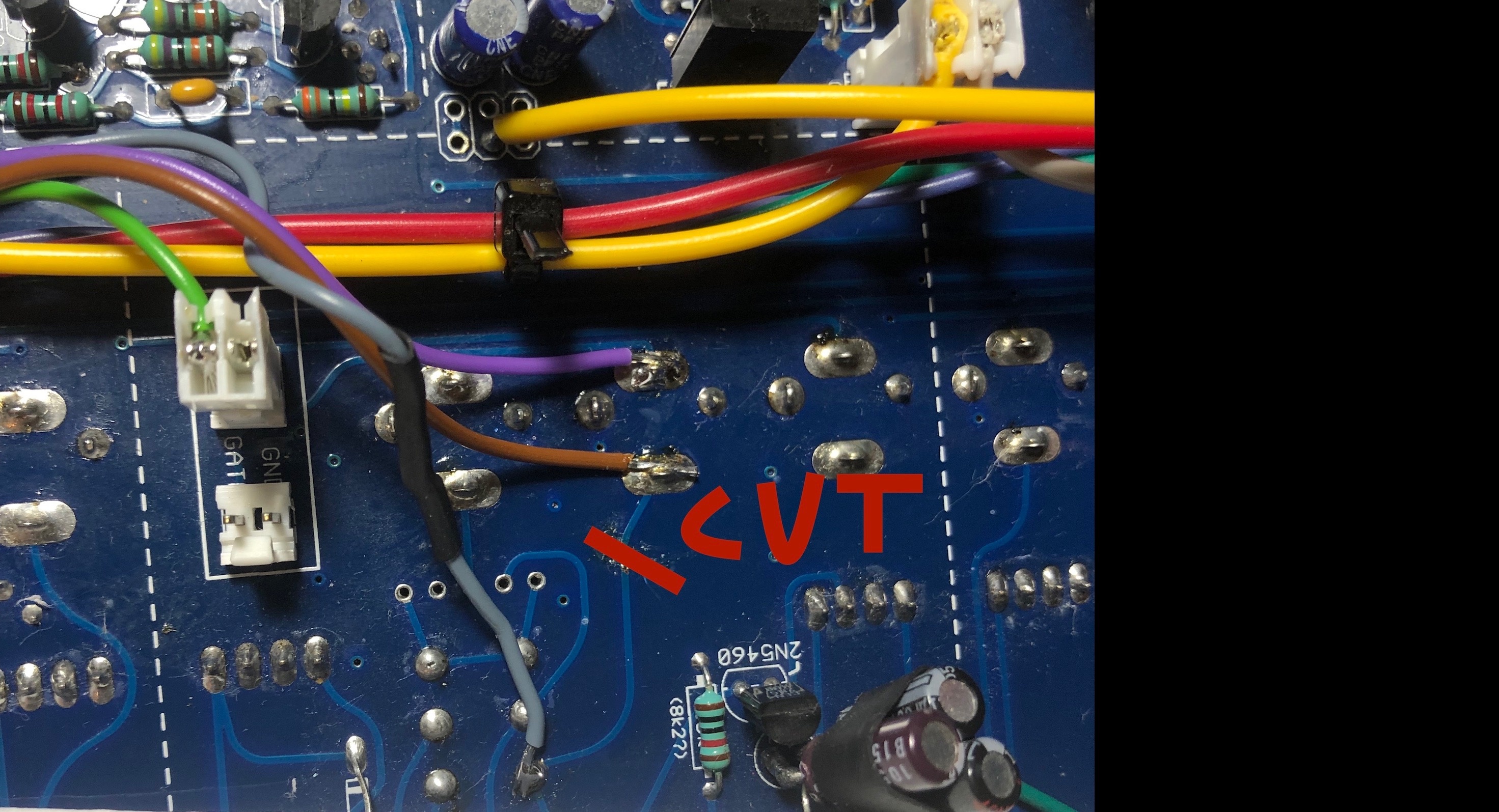
MIDI PCB GATE OUT (pin 10 is the last on right side) to GATE JACK Switch Pin
GATEBOOSTER INPUT (pin3) to GATE JACK TIP or use the MTA header (GATE)
GATEBOOSTER OUTPUT (GATE) to the SWITCH (clock/SH) upper left pin
GATEBOOSTER OUTPUT (Trigger) to the MTA Header TRIGGER
cut the trace between GATE INPUT jack and the SWITCH (clock/SH)
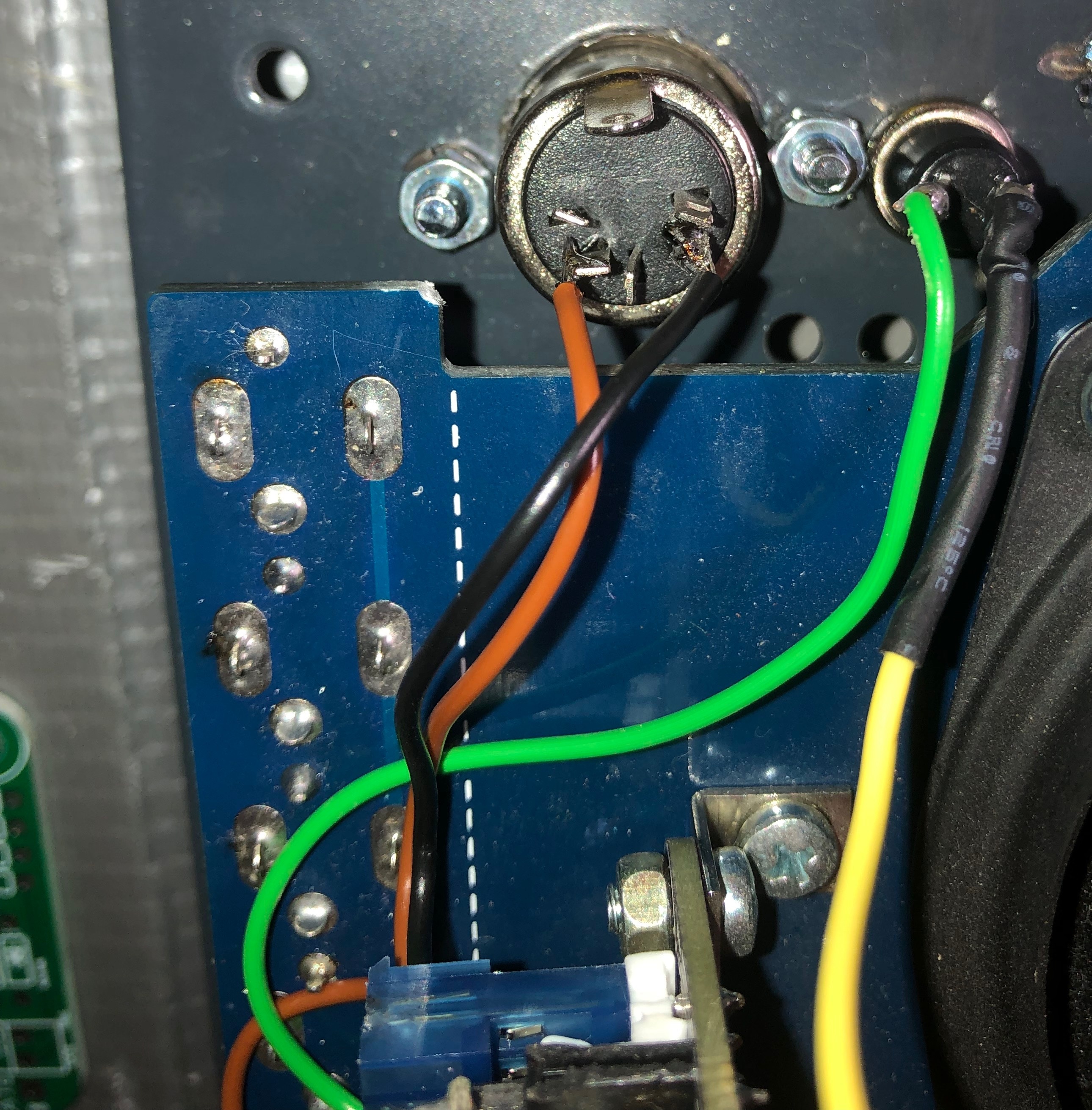
MIDI connector wiring:
 <wiring picture later here>
usecase description:
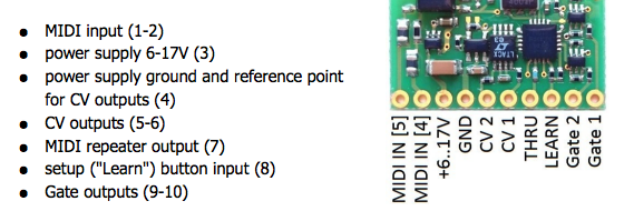
usage of MIDI: the midiimplant creates a 5V Gate signal, this goes thru the gate jack switch to tip pin - this is connected to the gatebooster input, the gatebooster boost the 5V to 10V and create a addional trigger signal,
...