Requirements:
good Solderstation
Soldercore 0,5mm & 1mm
BOM: (Bill of Material)
The PCB Set from DIYsynth.de contains:
...
24x 100nf RM2 polyester capacitors
what you need in total
| Line nr. | part | quantity | price | source | ||
|---|---|---|---|---|---|---|
| 1 | 1uF RM5 | 16 | ||||
| 2 | 4.7uF | 4 | ||||
| 3 | 100pF | 24 | ||||
| 4 | resistor 1K | 28 | ||||
| 5 | resistor 100k | 32 | ||||
| 6 | resistor 8.2R | 2 | ||||
| 7 | Ferrite beads - included in PCB set | 2 | ||||
| 8 | rectifier 1N4001/2/4/ | 2 | ||||
| 9 | MOTM MTA156 4pin header | 1 | ||||
| 10 | IC Socket 8pin round milled | 8 | ||||
| 11 | IC Socket 14pin round milled | 4 | ||||
| 12 | TL084 | 4 | ||||
| 13 | NE5532 | 8 | ||||
| 14 | jack 3 pin with switch | 4 | ||||
| 15 | jack 2 pin with or without switch (no switch at the jack needed here but feel free to use the same as above) | 28 | ||||
| 16 | 20pin header (you need in total 40 pins) | 2 or 4 | ||||
| 17 | 20pin socket (you need in total 40 pins) | 2 | when using 15mm spacer or 4 when using 20mm spacer | |||
| 18 | metal spacer (to hold the pcb) 15mm long M3* or use 20mm spacer | 4 | ||||
| 19 | nut, washer, screws M3 - that match to the metal spacer | depends on spacer | ||||
| 20 | solder core 1mm and 0,5mm ROHS preferred |
Steps to your completed device:
important Info: the logicboard is mounted with the components thru the ucb and lcb boards - like this:
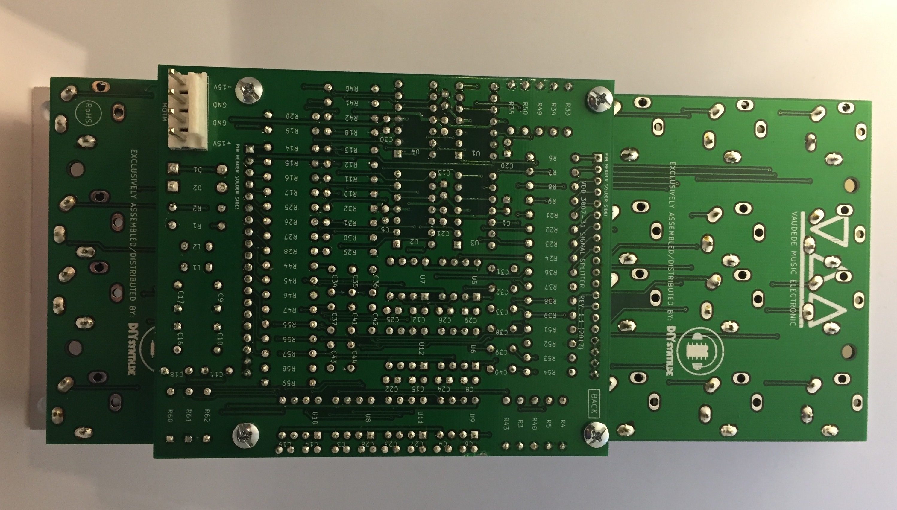
please read the guide before you start the build to understand my preferred guide, its possible to assemble the module in other ways too !
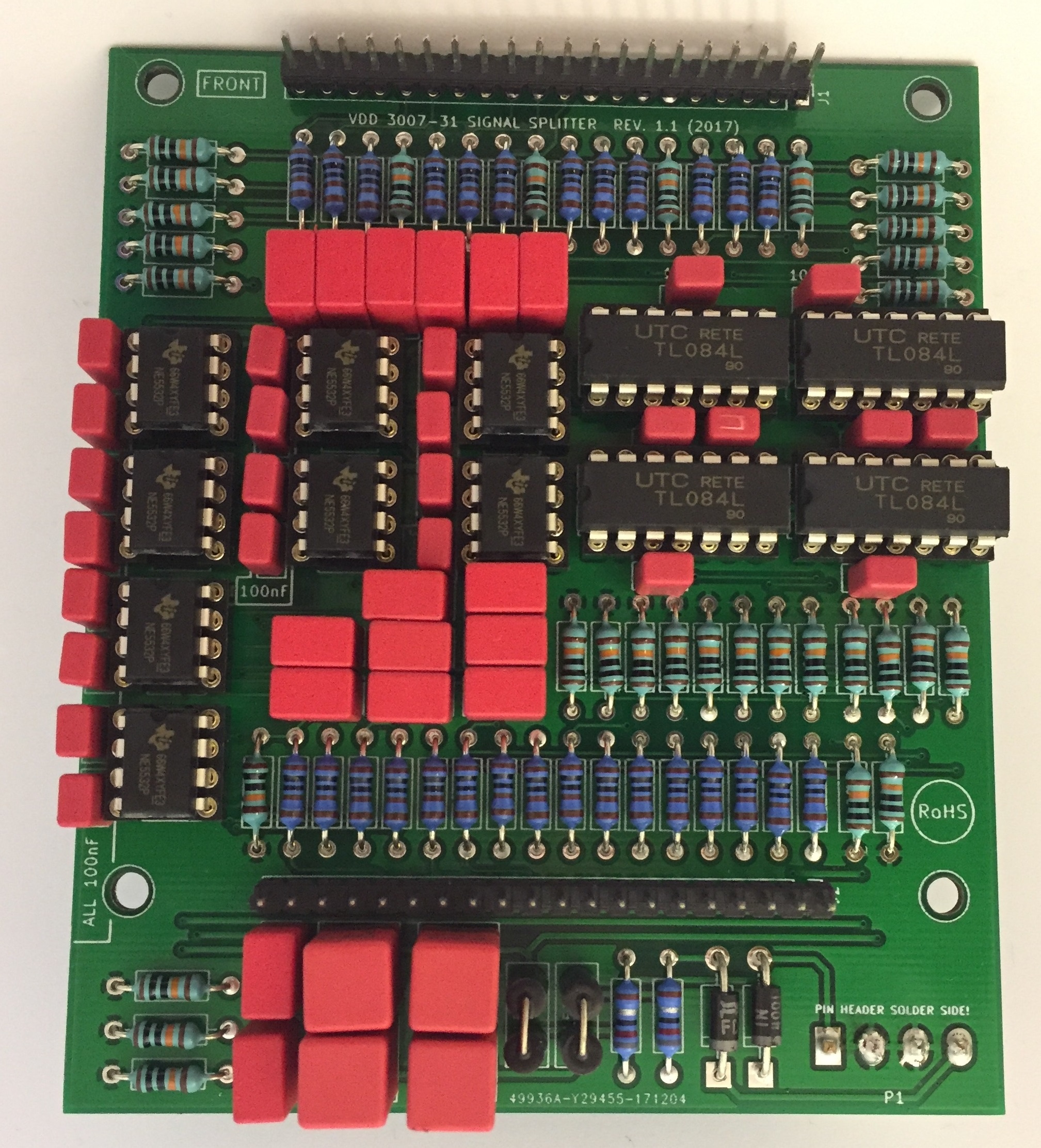
Logicboard
- start with the assembly of the Logicboard, don't attach both long headers !
- begin with the resistors you can solder from component side and turn the pcb - solder from solderside too.
- place and solder the rectifiers and ferrite beads
- place and solder the IC sockets (dont fit the ICs)
- place and solder the capacitors
- place the Power header (4pin MTA156) from solderside as shown here:
ucb & lcb PCB
| Warning |
|---|
make sure you use 3 pole (switched mono jacks) for the 4 top jacks ( IN A IN B , IN A IN B) |
...
- prepare the long headers: the distance between the controlbaord and logicboard must be 14-15mm, the big WIMA 4.7uF caps
the pinheaders are 7-8mm high, connect 2 together.
mount the male and female header together - the boards have a silkscreen layout for the 6,3mm jack - this is the component side !
- mount on the frontpanel with 4 jacks in each corner on one pcb, solder one pin on each jack, thats needed to have enough space to solder the pin headers like this:
...
14. if 13. is ok - add all ICS and test the module
testing process Active Splitter
...
this signal can be found now second Out row.
testing process buffered multiple:
...
this signal can be found now second Out row.