...
Procedure:
The good news is that if you already have your PCB and Panel put together, you don't need to separate them or cut traces to perform this mod.
Unfortunately, the image I have is not very good, so I'll try to describe it as best I can.
On the Internal Clock page of the schematic, at the common point between R376 (22k) and R375 (10k), there is a trace that runs down and makes contact with output of the Internal Clock circuit. Break this connection by lifting one end of both resistors from the board. The ends of these resistors that face the bottom of the board are the ones you lift. You will find these two resistors side by side, below a 1N cap. One of these ends is silkscreened as a test point for the Electronic Clock.
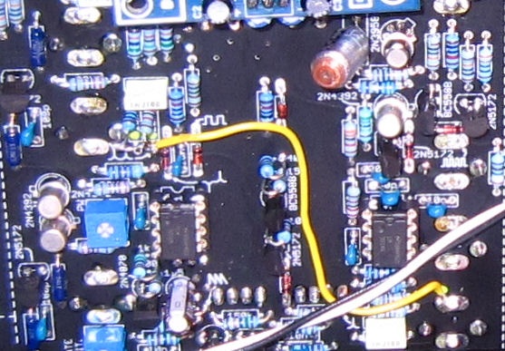
Run a jumper that is soldered to both the the freed resistor leads at one end, and connected to the tip pin of the External Clock in jack at the other. Here is my lousy pic.
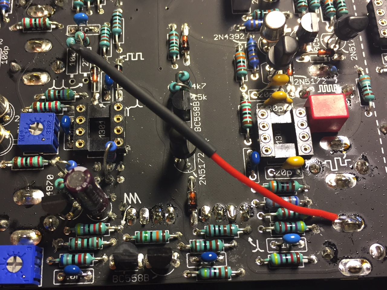
new picture from LED-man - the 10K and 22K is lifted up on a new TTSH rev.3 build
...