Manual:
https://help.mikrotik.com/docs/display/UM/Chateau+5G+ax
open:
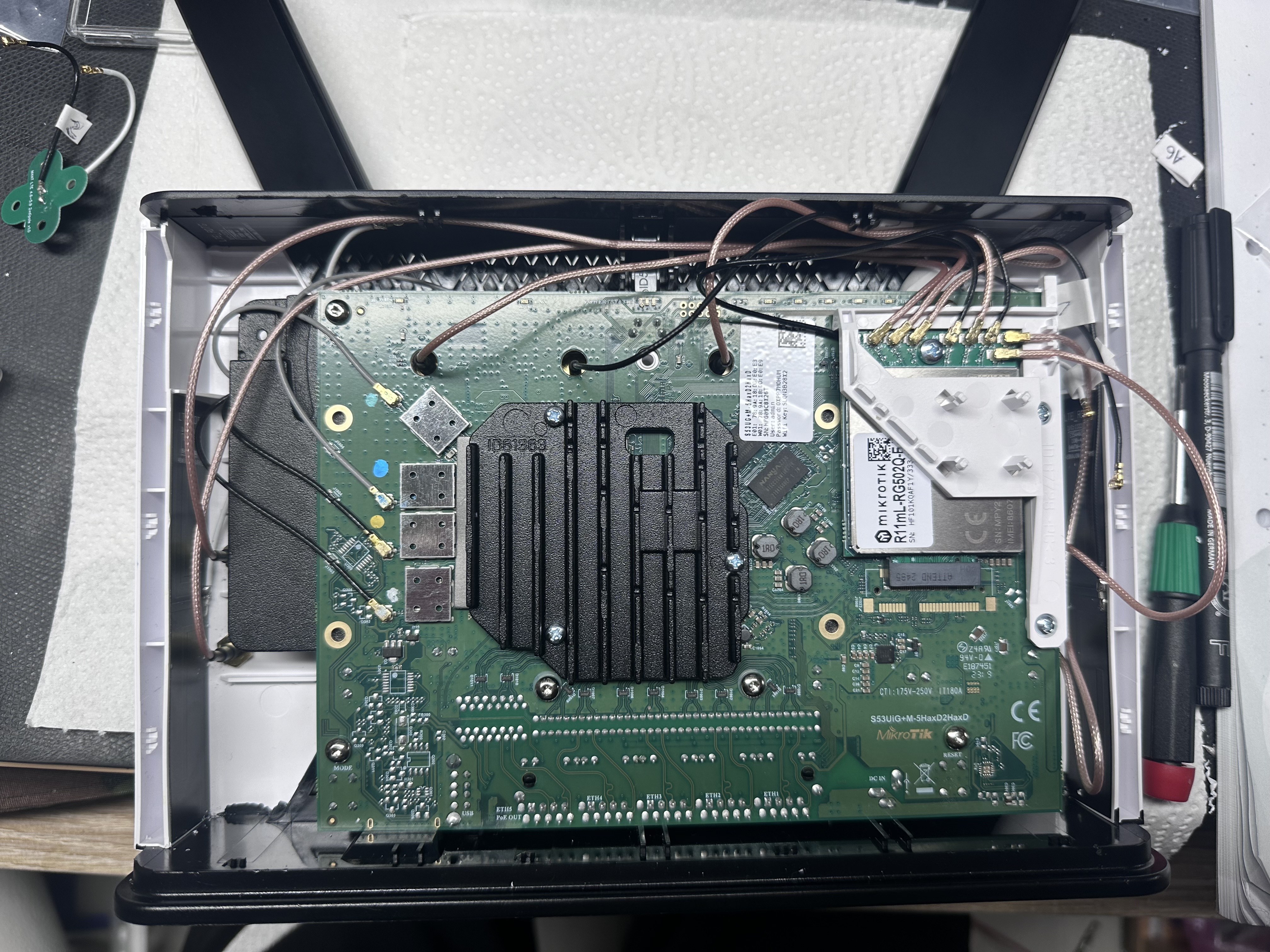
"To remove the cover, first remove the rear screw, then carefully separate the front chassis part at the top a d bottom using a Spudger or similar DIY repair tool, until the front cover lifts off. I came across this YouTube video for opening the Chateau LTE12, which has the same outer case as the 5G model. "
5G Model: AX version !!
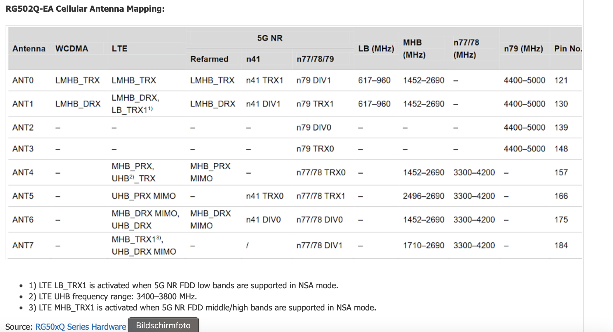
"With the external antenna connections, you will unlikely need to connect anything leading to modem ports A2 or A3 as these are for 5G band n79 (4.4-5GHz), which is currently only used in a few Asian countries such as China, Hong Kong and Japan."
"All the ports ANT0 through to ANT7 on the modem are mobile data connection ports. The Wi-Fi connection ports are separate on the main board"
"Connect one set of antennas to ANT0+1 and the second set of antennas to ANT6+7." for 4x4 WIMO (valid for AX Version)
Valid for 5G (non AX version):
Frequency bands in table
LB = Low Bands - All bands up to 960MHz
LMHB = Low/Middle/High Bands - All bands up to 2690MHz
MHB = Middle/High Bands - All bands from 1452MHz or 1710MHz to 2690MHz
UHB = Ultra High Bands - Bands from 3400 to 3800MHz
4G LTE Antenna connections
TRX = Transmit/Receive - Antenna #1 for 2x2 or 4x4 MIMO
DRX = Diversity Receive - Antenna #2 for 2x2 or 4x4 MIMO
PRX MIMO = Primary Receive #2 - Antenna #3 for 4x4 MIMO
DRX MIMO = Diversity Receive #2 - Antenna #4 for 4x4 MIMO
TRX1 = LTE Antenna #1 paired with a 5G NSA connection over FDD LMH bands (see table notes 1 & 3 above)
5G NR Antenna connections
TRX(0) - Transmit/Receive - Antenna #1 for 2x2 or 4x4 MIMO
DRX(0) - Diversity Receive - Antenna #2 for 2x2 or 4x4 MIMO
TRX1 - Transmit/Receive #2 - Antenna #3 for 4x4 MIMO
DRX1 - Diversity Receive #2 - Antenna #4 for 4x4 MIMO
source: https://confusedbird.com/thread-119-post-1151.html
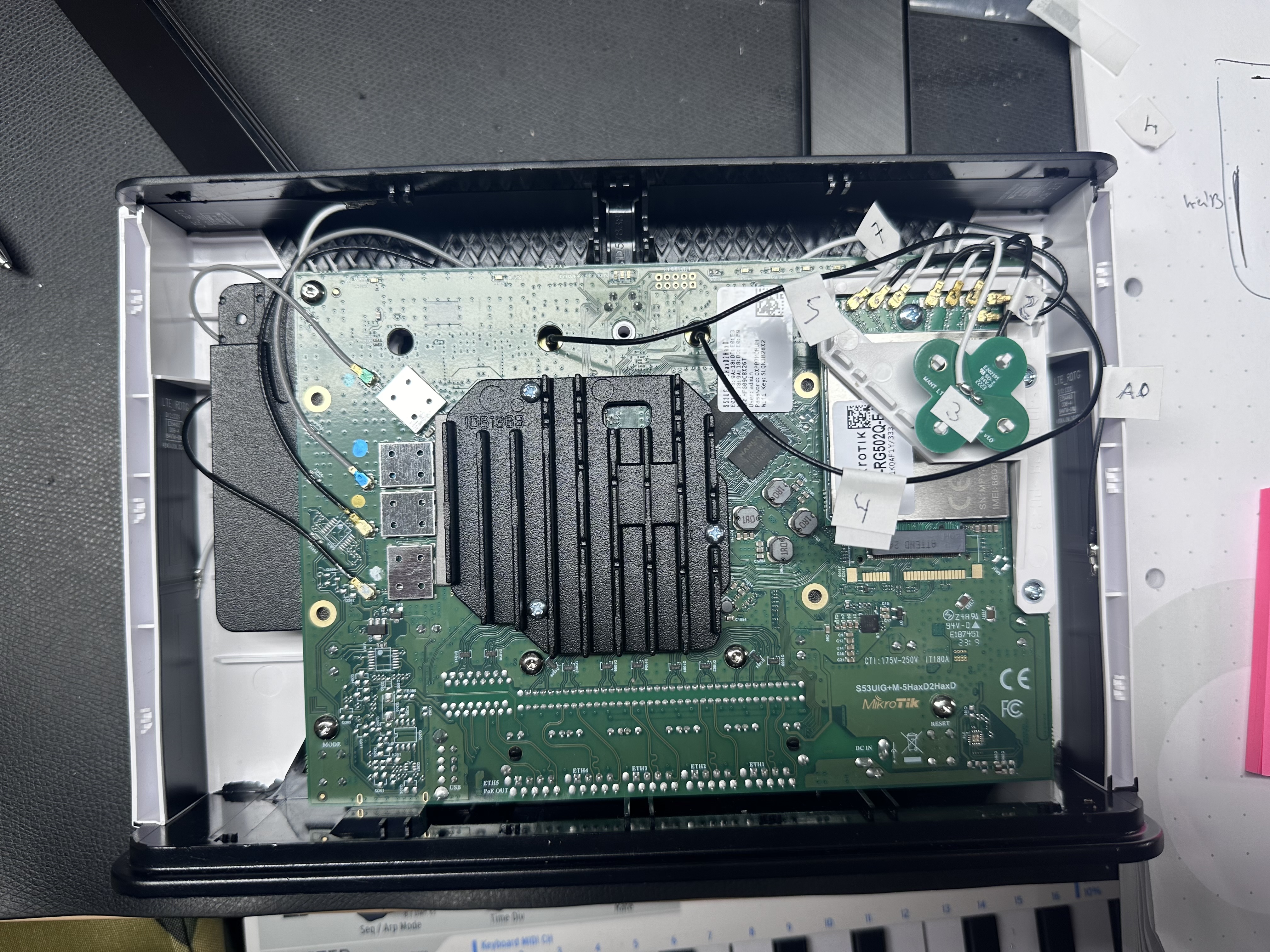
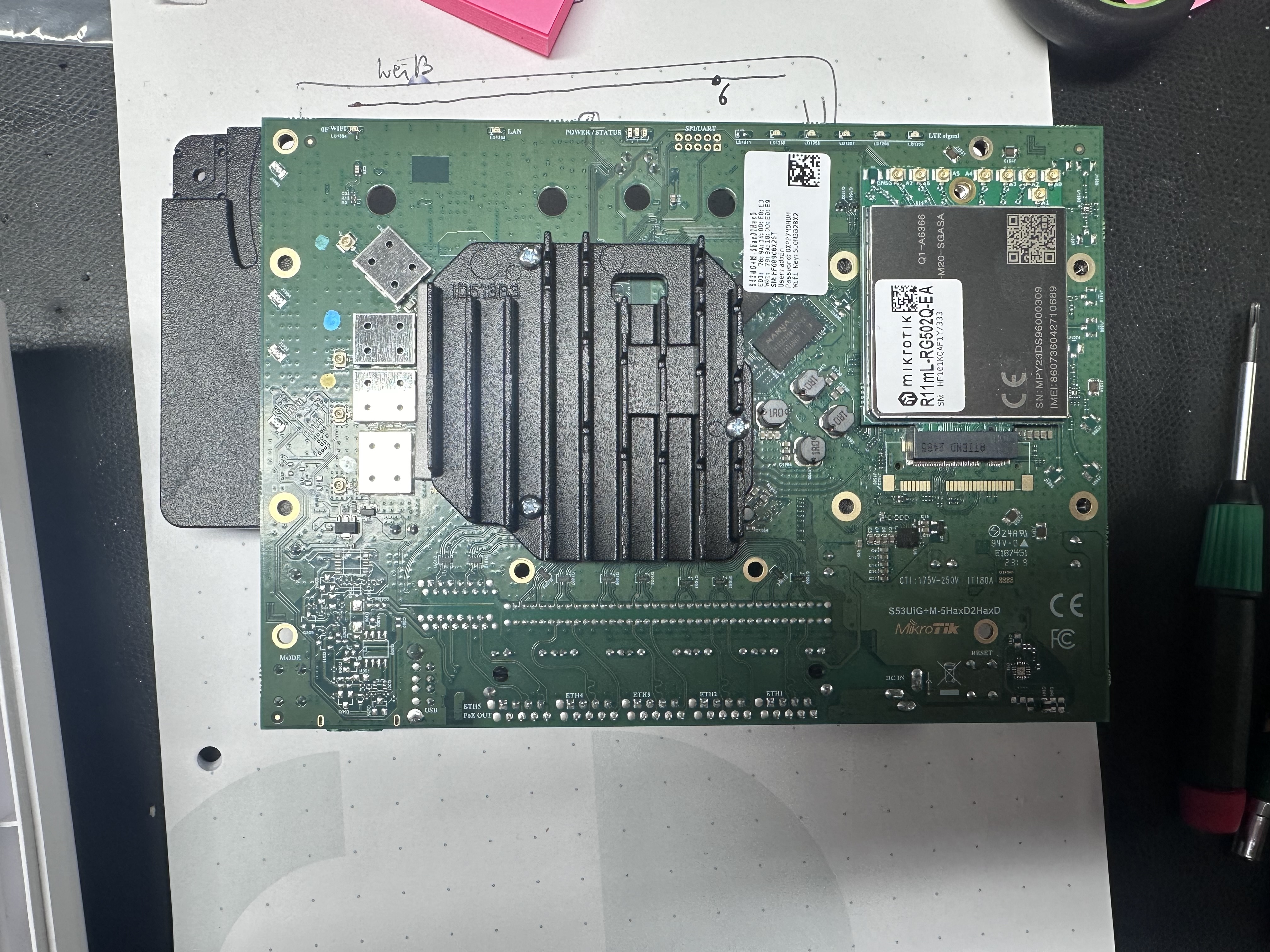
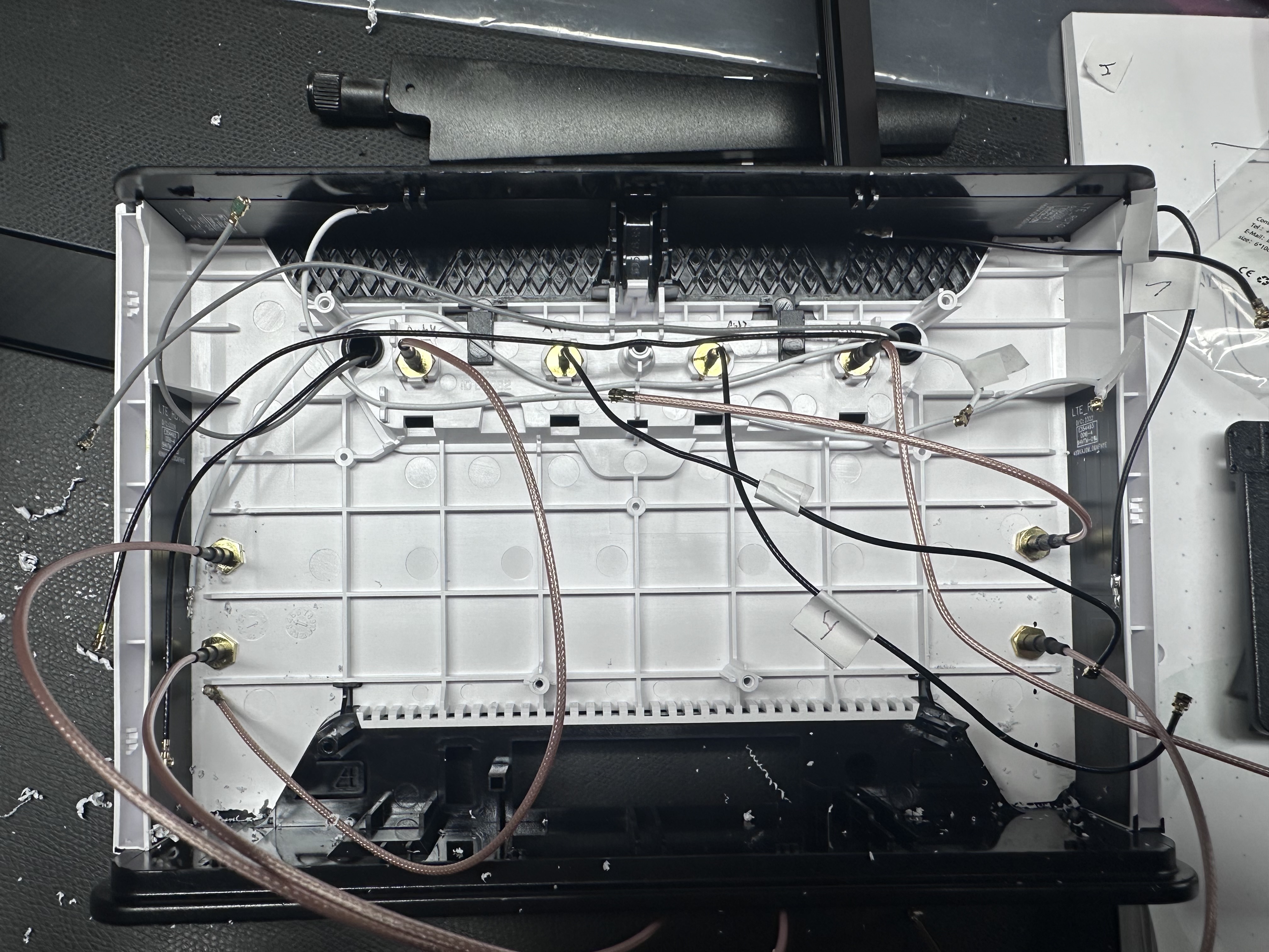
Original wiring:
port A0 = top left internal Antenna ![]()
port A1= right Antenne ![]()
port A2 on x pcb bottom ![]()
port A3 on X pcb soldered ![]()
port A4 on Antenne Connector on Ant2 ![]()
port A5 on Antenne Connector Ant1 ![]()
port A6 = upper side antenna soldered on right side (upper antenna on chassis) ![]()
port A7 = left side antenna soldered on left side (upper antenna on chassis) ![]()
Source: https://confusedbird.com/thread-119.html
For the fastest upload speed with a 4G only connection that utilises upload carrier aggregation, use the following antenna configuration:
Valid for 5G AX Version:
2x2 MIMO antenna:
A0 - Lead #1 of 2x2 MIMO antenna
A7 - Lead #2 of 2x2 MIMO antenna
4x4 MIMO antenna:
A0 - Lead #1 of 4x4 MIMO antenna
A1 - Lead #2 of 4x4 MIMO antenna
A6 - Lead #3 of 4x4 MIMO antenna
A7 - Lead #4 of 4x4 MIMO antenna
Two 2x2 MIMO antennas:
A0 - Lead #1 of 2x2 MIMO antenna 1 (+/-45 Degrees)
A1 - Lead #2 of 2x2 MIMO antenna 1 (+/-45 Degrees)
A6 - Lead #1 of 2x2 MIMO antenna 2 (Vertical/Horizontal)
A7 - Lead #2 of 2x2 MIMO antenna 2 (Vertical/Horizontal)
own note: 60cm distance in height between the 2 pairs in 2x2 MIMO config
Security Improvement: ⚠️
You should use a separate real server and use a VLAN to "dialup" or use a VLAN to route it on a separate server or in an enterprise WLAN Insfratructure on separate SSIDs to get the max. of security configuration by network separation, routing thru a other firewall/NAT/IDS/IPS.
Do not use this pics for Mods, please respect the copyright of this pictures ! thanks