...
- install the SMT capacitors as before described in the Breakoutboard section.
- install the SMT ICs
- install the resistors - solder all pins, do not install the Tempco Resistor yet
- install the ceramic capacitors - solder all pins
- install the IC sockets - standard IC sockets preferred - solder all pins after you have checked the alignment
- install the matched Transistor pair (2N3904), regulators - do not overheat the pins here
- look in my above guide - about the 240pf capacitors - maybe you have to select or match something - its not needed but for some builders just a notice
- install the Filmcapacitors/Electrolyte caps and solder one pin - align the capacitors before you solder the second pins.
- wash the pcbs as described before
- when the pcbs are dry - install the Trimmers
- install all ICS
- install the Tempco resistors - this must be thermal connected, use thermal paste
- use shrink tube for the 2N3904 pair and thermal paste
- double and triple check the IC orientation
Hardwareboard part 2: (read this before you start)
- install the 12mm spacer on the HW.board,
- then put on the mainboard the opposite part
- then put the boards together and fix the pcbs with few screws on the spacers
- then solder the 10pin dual row header/socket all pins - solder both parts completely before you remove the pcbs again (otherwise some pins can be accidentally removed)
- clean these solderpoints with eartips carefully.
- remove the screws and disassembly the pcbs
- --------
- install the sliders on the Hardware Board, and carefully solder them - pin by pin - as described in the above table (do not overheat the parts)
...
10. the last parts can be installed with one step or step by step - but in this case, you have to remove the frontpanel a few times. (customers with experience from DDRM/Kijimi can try to install the pots, OLED, LEDs, tactiles and the tactile caps in one step)
11. cut/remove the locker pin on the potentiometers potentiometers
12. the potentiometer must be installed with the front panel attached for best alignment - please note: one Potentiometer is not Center detent !! its marked on the pcb without an line in the circle.(volume pot)
13. the potentiometer have to sit on the pcb - do not try to to install the potentiometers in a higher position (or you can run in problems with the knob height)
...
| Panel | ||
|---|---|---|
| ||
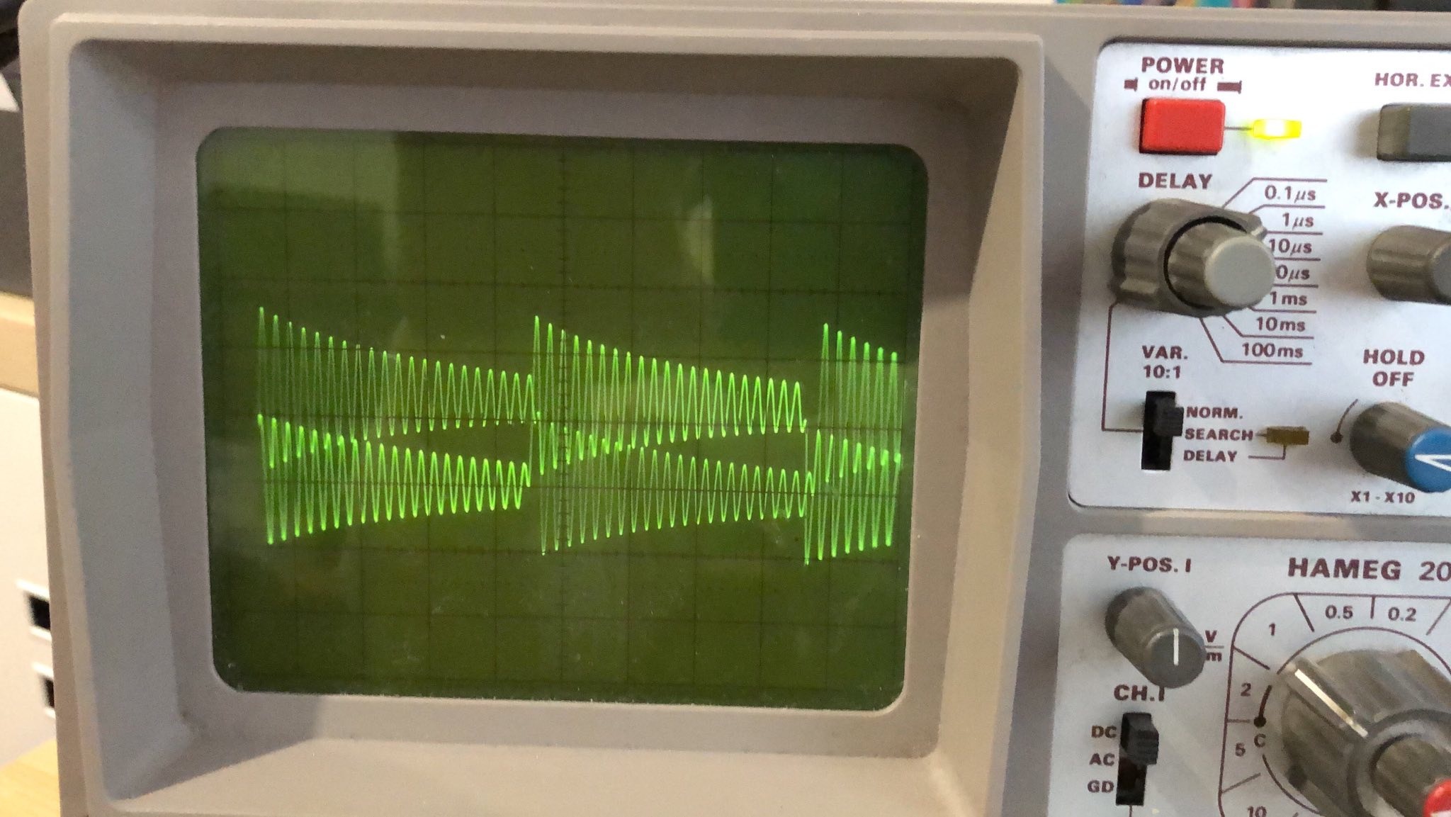
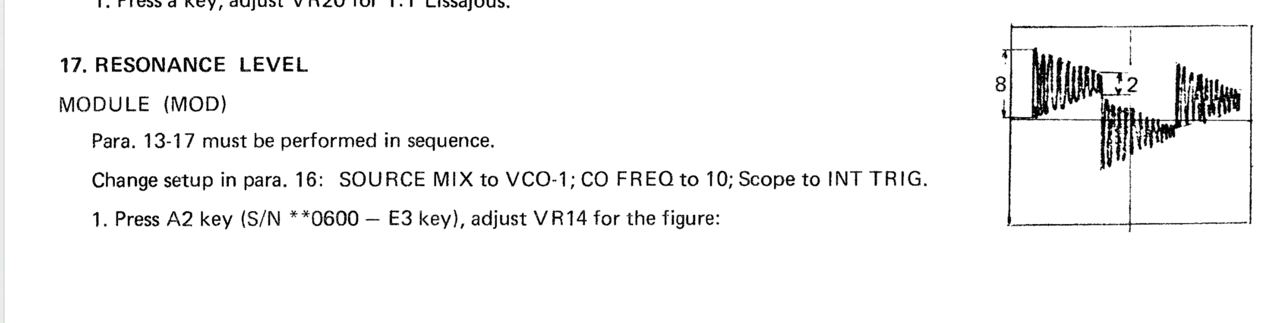
Here is a step by step guide to calibrate the filter resonance: (ONLY AFTER that you need to calibrate filters in further step)It´s recommend turning the resonance trimmer TR1 fully clockwise on each voicecard to make this procedure as easy as possible! 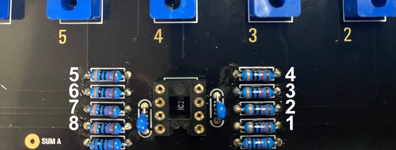 The best way is to use 8 resistors on the mainboard for making a measurement. 1. Warm up your unit about 30-40 mins 2. turn on ISE-NIN, Go to menu (press shift (grey cap button) + Back (middle button under the display), then calibration, choose resonance (The display should read: "card 1" and you should hear a test tone through the outputs (for the next voice card you can press the "next (Back)" button to cycle through the voice cards) 3. Connect a Scope probe on the Mainboard, to the resistor of the card which you calibrate , set your oscilloscope to "timebase 0.5ms/cm" and "1V/cm" 4. You should see the filter signal on your scope. If you have turned the trimmer fully clockwise the signal should be- and sound distorted. now turn the "resonance" trimmer TR1 on the Voicecard anti- clockwise until you get a clean signal as in the picture below (The difference of maximum and minimum amplitude in one cycle has to be 4-times.). Comment from Black Corp: "We especially made all settings in resonanse calibration how they should be (square, cutoff, 12db etc)."
Congratulations, you have successfilly calibrated the filter resonance for all of the voices! Resonance calibration Method according to the Roland Jupiter-8 service manual (not recommended yet → use above method!!!):Go into MENU, CALIBRATION, RESONANCE. Follow these steps from the Jupiter 8 manual, turning Trim1 for each voice (or see below):
Workaround or turn Trim TR1 until the self oscillation is off on each voice. you can switch between the cards using the switch button on the mother board. |
...