...
- install the resistors and diodes
- install the ceramic capacitors (not the electrolyte caps yet)
- install the TO-220 regulators (IC4, IC5, IC7), the black isolated regulators do not match with the pcb holes, its not important. bend the pins as short as possible that they can be soldered from the rear-side of the pcb
- install IC3 - I prefer without a socket for better thermal regulation, but should be fine with a socket too.
- install the electrolyte caps
- install the LEDs - LED orientation - the square pad is ground (short leg) its the flat side of the LED designator
- install the fuse socket and MTA 156 2pole header
- install the DC-DC bricks (IC1, IC2)
- Double check the IC orientation and part values, Capacitor polarity
- wash the PCB carefully and let they dry over night
- optional - use a bench psu for testing with current limiter 12v/200mA 250mA don't use a smaller current limit to avoid problems while start, the 200mA 250mA is a given value without any devices connected
- must do: all LEDs must be on, check against the given PCB voltages - all voltages must be correct
...
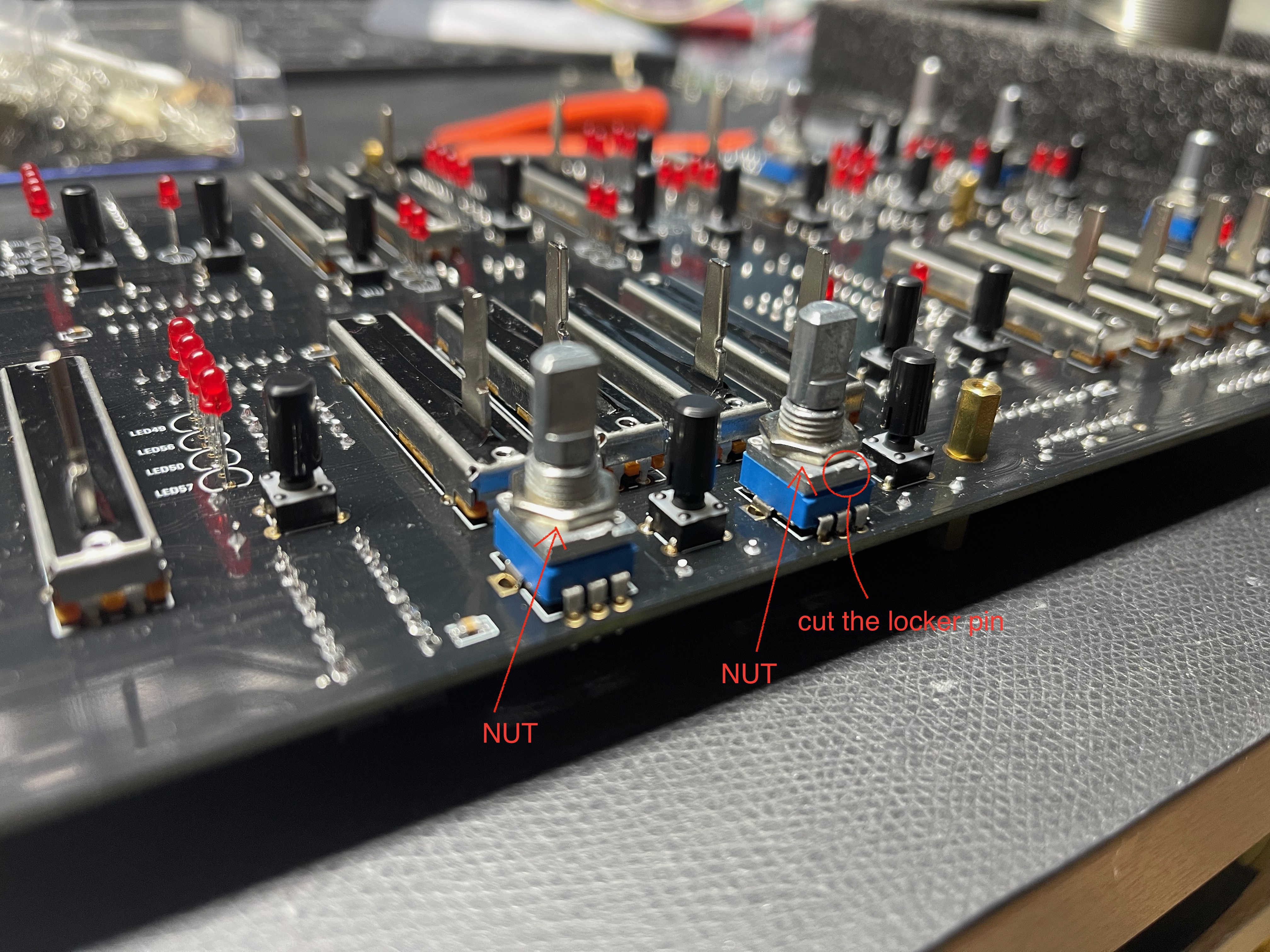
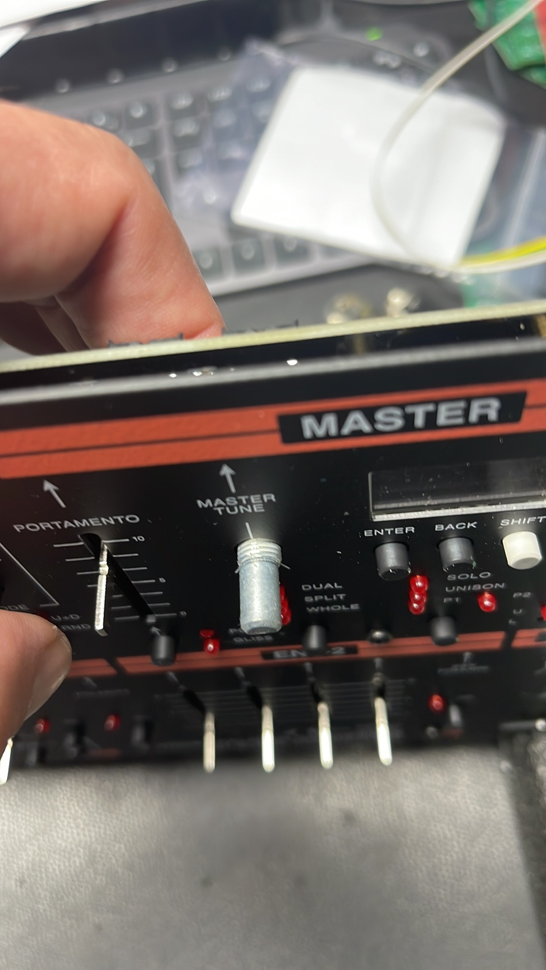
DO NOT try to install the nut on the frontpanel side !! install a nut as shown below .
15. OLED - install 2x M2 5mm Spacers on the OLED (you dont need 4 spacers) and respect the pinout as described in the Information List ID2 - its important to double check the pinout and measure the GND pad of the OLED against other GND pads on the HW.Board.
be careful with the OLED !!
LEDs:
here´s an example how to install the LEDs easily:
...
Test the PSU without BB - on a bench psu with current limiter 200mA 250mA only the PSU.
with mainboard connected 1000mA (without Voicecard)
with one card try 1000mA- with all cards up to 2.000mA
...