...
Power supply PCB (PSUb) -
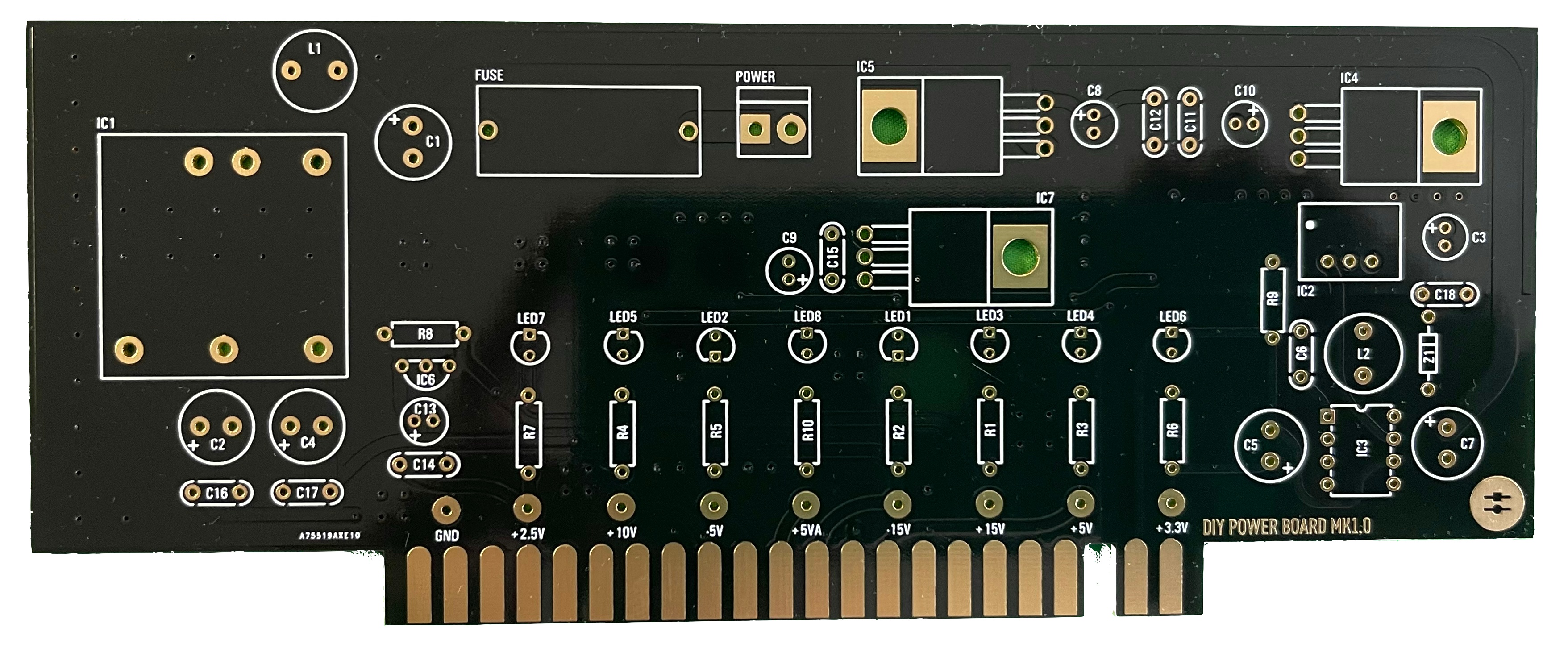
- install the resistors and diodes
- install the ceramic capacitors (not the electrolyte caps yet)
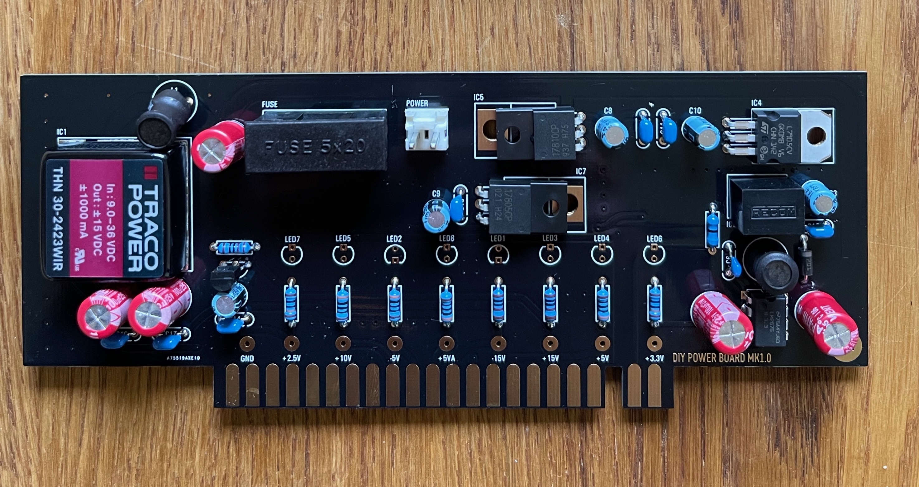
- install the TO-220 regulators (IC4, IC5, IC7), the black isolated regulators do not match with the pcb holes, its not important.
...
- bend the pins as short as possible that they can be soldered from the rear-side of the pcb
- install IC3 - I prefer without a socket for better thermal regulation, but should be fine with a socket too.
- install the electrolyte caps
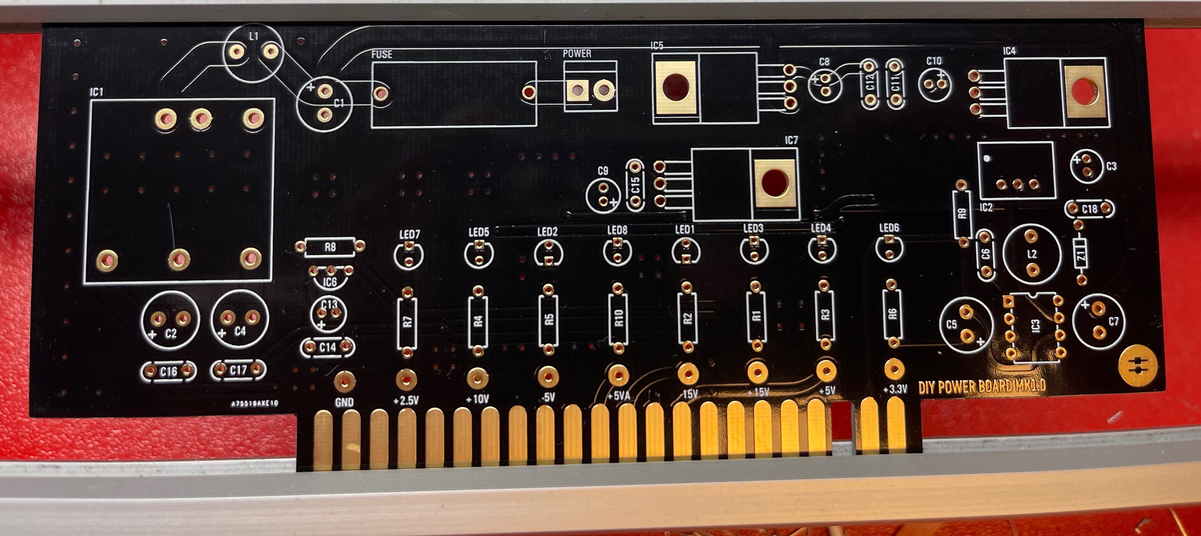
- install the LEDs - LED orientation - the square pad is ground (short leg) its the flat side of the LED designator
- install the fuse socket and MTA 156 2pole header
- install the DC-DC bricks (IC1, IC2)
- Double check the IC orientation and part values, Capacitor polarity
- wash the PCB carefully and let they dry over night
- optional - use a bench psu for testing with current limiter 12v/200mA don't use a smaller current limit to avoid problems while start, the 200mA is a given value without any devices connected
- must do: all LEDs must be on, check against the given PCB voltages - all voltages must be correct
LED orientation - the square pad is ground - short leg
I DIDN´T install a socket for the 8pin IC.
...
first test on a bench PSU with current limit at 12v/200mA
...