...
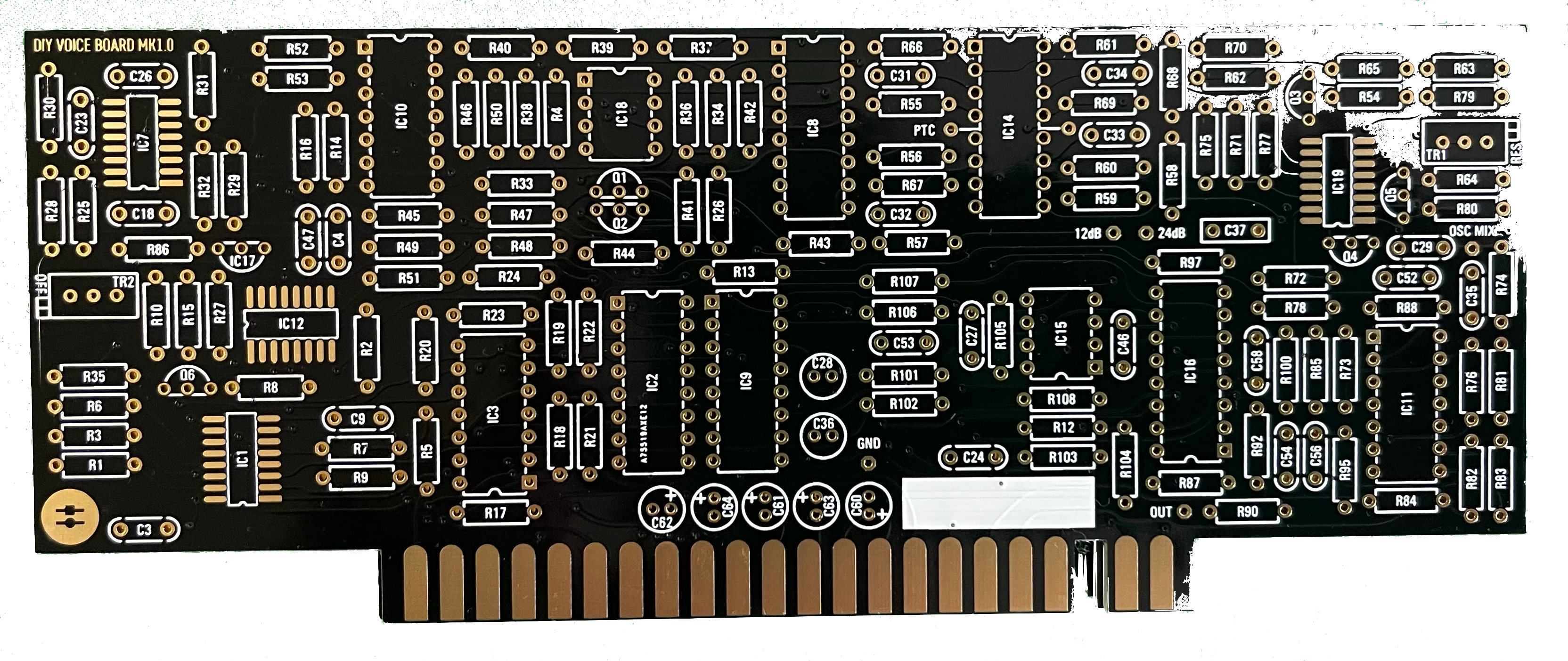
- install the SMT capacitors as before described in the Breakoutboard section.
- install the SMT ICs
- install the resistors - solder all pins, do not install the Tempco Resistor yet
- install the ceramic capacitors - solder all pins
- install the IC sockets - standard IC sockets preferred - solder all pins after you have checked the alignment
- install the Transistors/regulators - do not overheat the pins here
- look in my above guide - about the 240pf capacitors - maybe you have to select or match something - its not needed but for some builders just a notice
- install the Filmcapacitors/Electrolyte caps and solder one pin - align the capacitors before you solder the second pins.
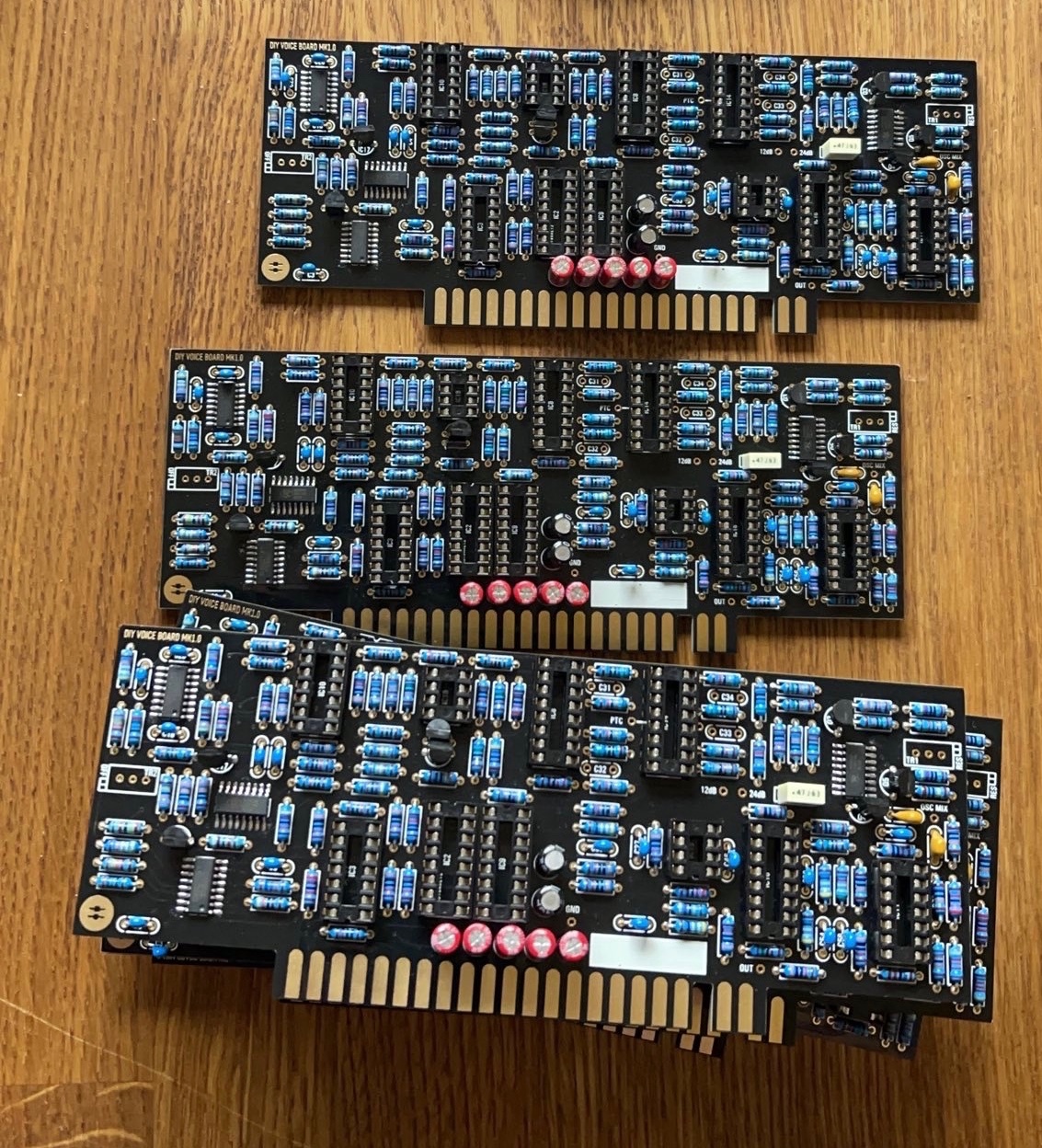
- wash the pcbs as described before
- when the pcbs are dry - install the Trimmers
- install all ICS
- install the Tempco resistors - this must be thermal connected, use thermal paste
- double and triple check the IC orientation
Hardwareboard part 2:
- install the 12mm spacer on the HW.board,
...
- then put on the mainboard the opposite part
- then put the boards together and fix the pcbs with few screws on the spacers
- then solder the 10pin dual row header/socket all pins - solder both parts
...
- completely before you remove the pcbs again (otherwise some pins can be accidentally removed)
- clean these solderpoints with eartips carefully.
- remove the screws and disassembly the pcbs
- --------
- install the sliders on the Hardware Board, and carefully solder them - pin by pin - as described in the above table (do not overheat the parts)
finally we can move to the last steps:steps which can be done in different ways
9. install the tactile switches and solder these., solder 1-2 per switch - not all pins together to have less heat on the part.
10. the the last parts can be installed with one step or step by step - but in this case, you have to remove the frontpanel a few times. (customers with experience from DDRM/Kijimi can try to install the pots, OLED, LEDs, tactiles in one step)step)
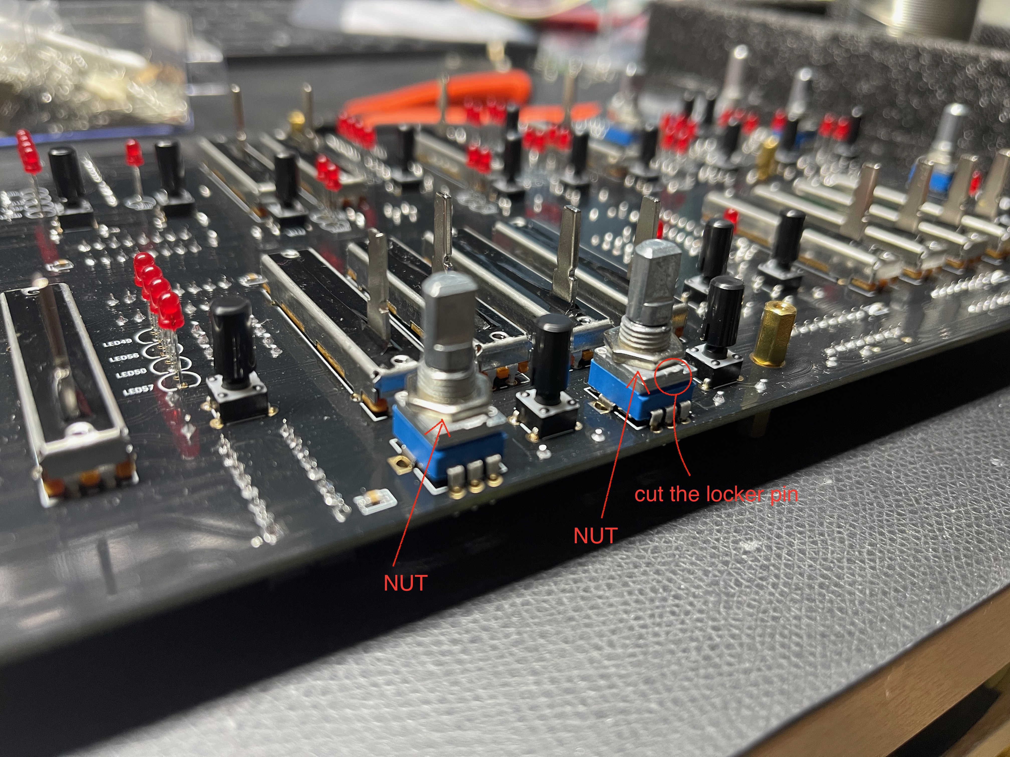
11. cut/remove the locker pin on the potentiometers
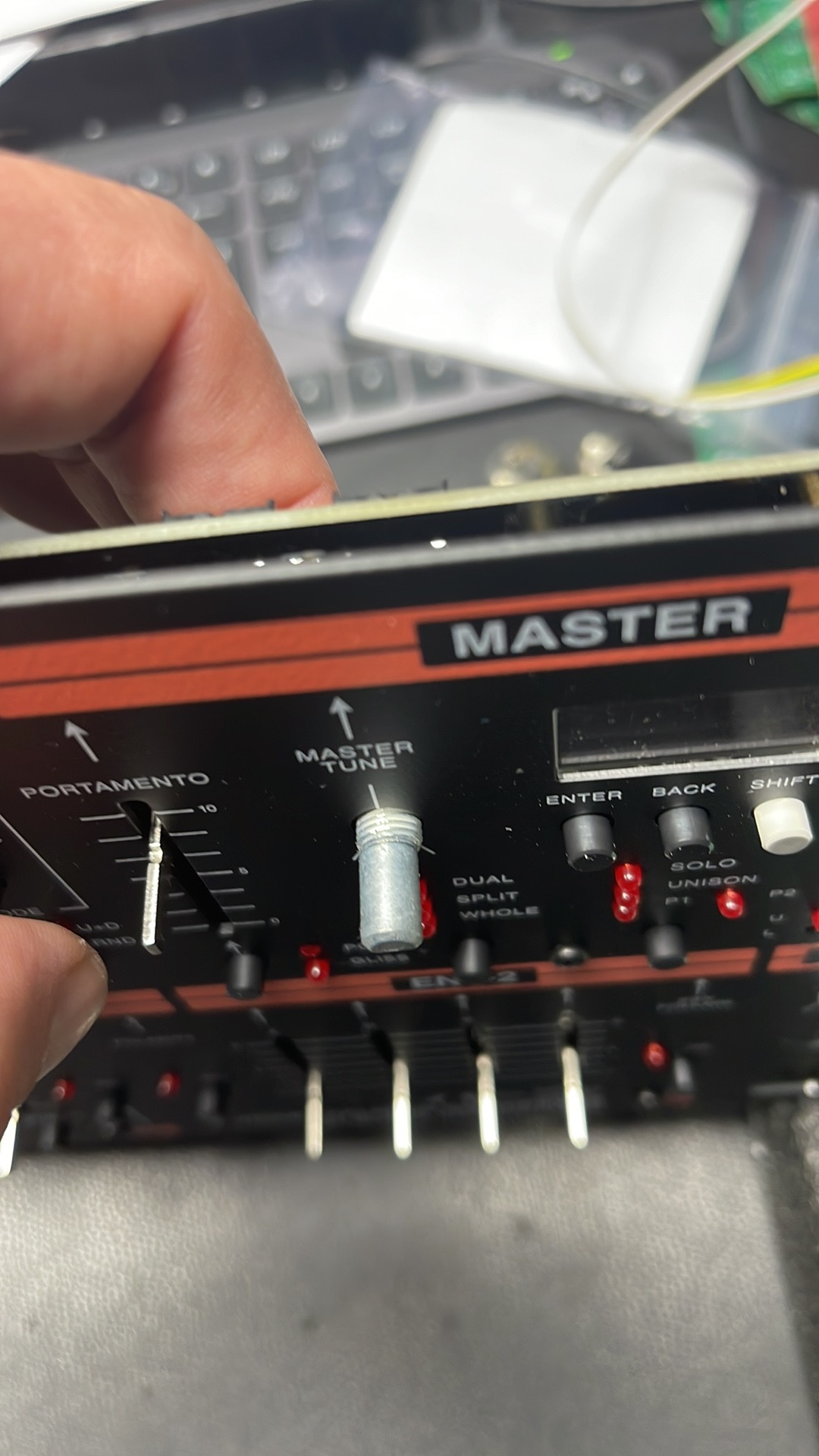
12. the potentiometer must be installed with the front panel attached for best alignment
13. the potentiometer have to sit on the pcb - do not try to to install the potentiometers in a higher position (or you can run in problems with the knob height)
14. , there are 2 options how to do that.. but my shown option should be the best with separate nuts (no wobbling pots)
DO NOT try to install the nut on the frontpanel side !! cut the locker pin on the potentiometers, install install a nut as shown below .
...