...
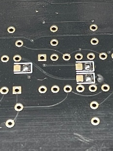
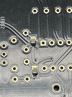
here´s an example how this has been installed by me, add some solder on one pad and heat up this pad while you move a capacitor with a tweezer to the location, then add some solder on the other side too, normally no extra flux (fluxpen) is needed but depends on your skills.
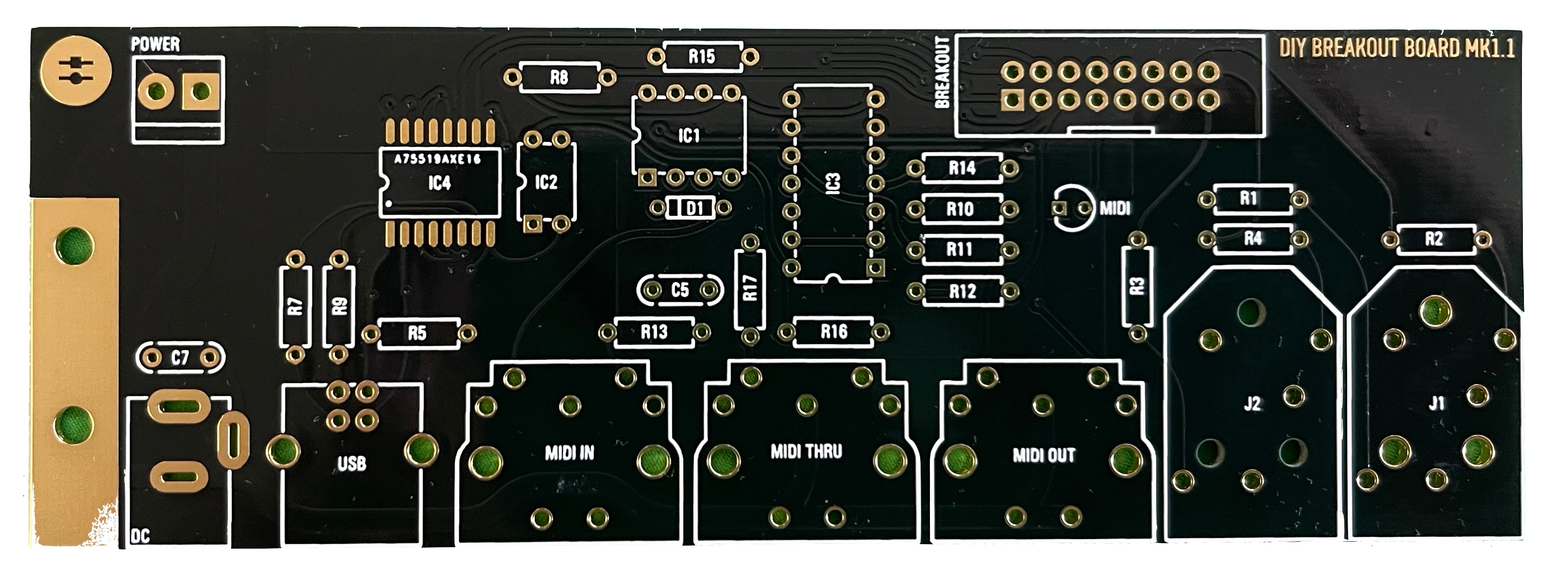
- install the
...
- SMT capacitors and IC4 (the dot on the PCB is pin1)
- install the resistors - solder all pins.
- install the ceramic capacitors - solder all pins
- install the IC sockets - standard IC sockets preferred - solder all pins after you have checked the alignment
- install the power socket, MTA156 header,
...
- 16pin IDC connector
- wash/clean the pcb before you install the USB
...
- socket, MIDI socket, Audio jacks
- wash/clean the pcbs carefully with respect on ESD safe handling
- install the USB and Midi Socket, Audio jacks
- Double and triple check the IC orientation
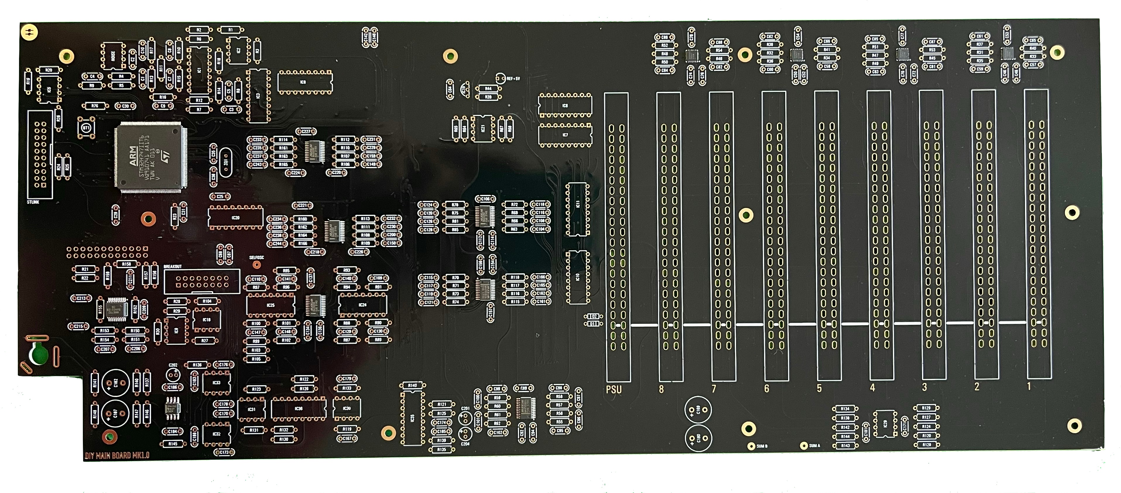
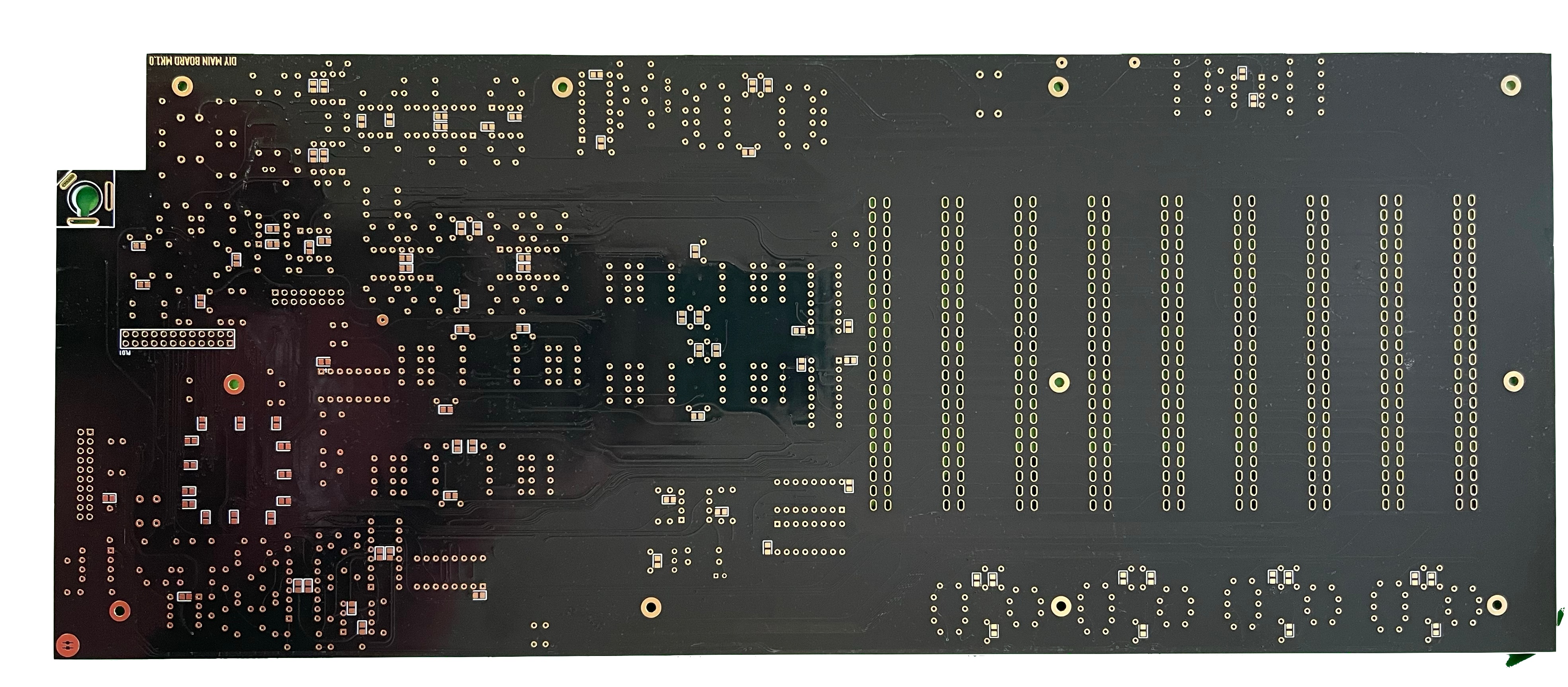
Mainboard (MB)
the heart of the ISE-NIN must be build really carefully !!
...
- install the SMT capacitors as before described in the Breakoutboard section.
- install the resistors - solder all pins.
- install the ceramic capacitors - solder all pins
- install the IC sockets - standard IC sockets preferred - solder all pins after you have checked the alignment
- install the Transistors/regulators, quartz - do not overheat the pins here
- install the Filmcapacitors/Electrolyte caps and solder one pin - align the capacitors before you solder the second pins.
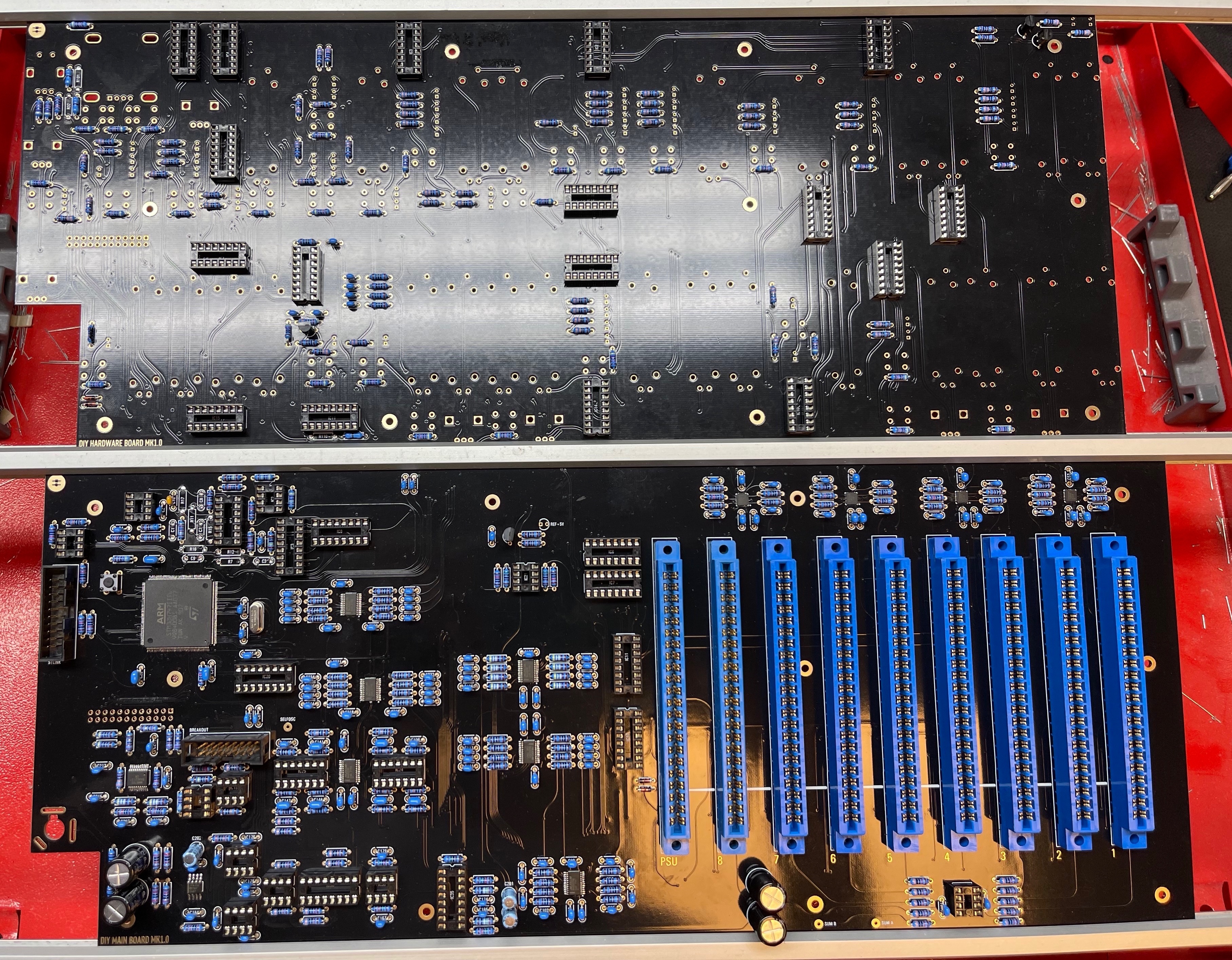
- install the EDGE connectors - solder only at top and bottom a pin and check the alignment, solder from left to right to minimize overheat problems with the connectors.
- don't forget to solder bridges at the white flat line on the EDGE cards as shown in the above table.
- check the soldering on the EDGE card pins carefully for shorts/solder bridges.
- wash/clean the pcbs carefully with respect on ESD safe handling
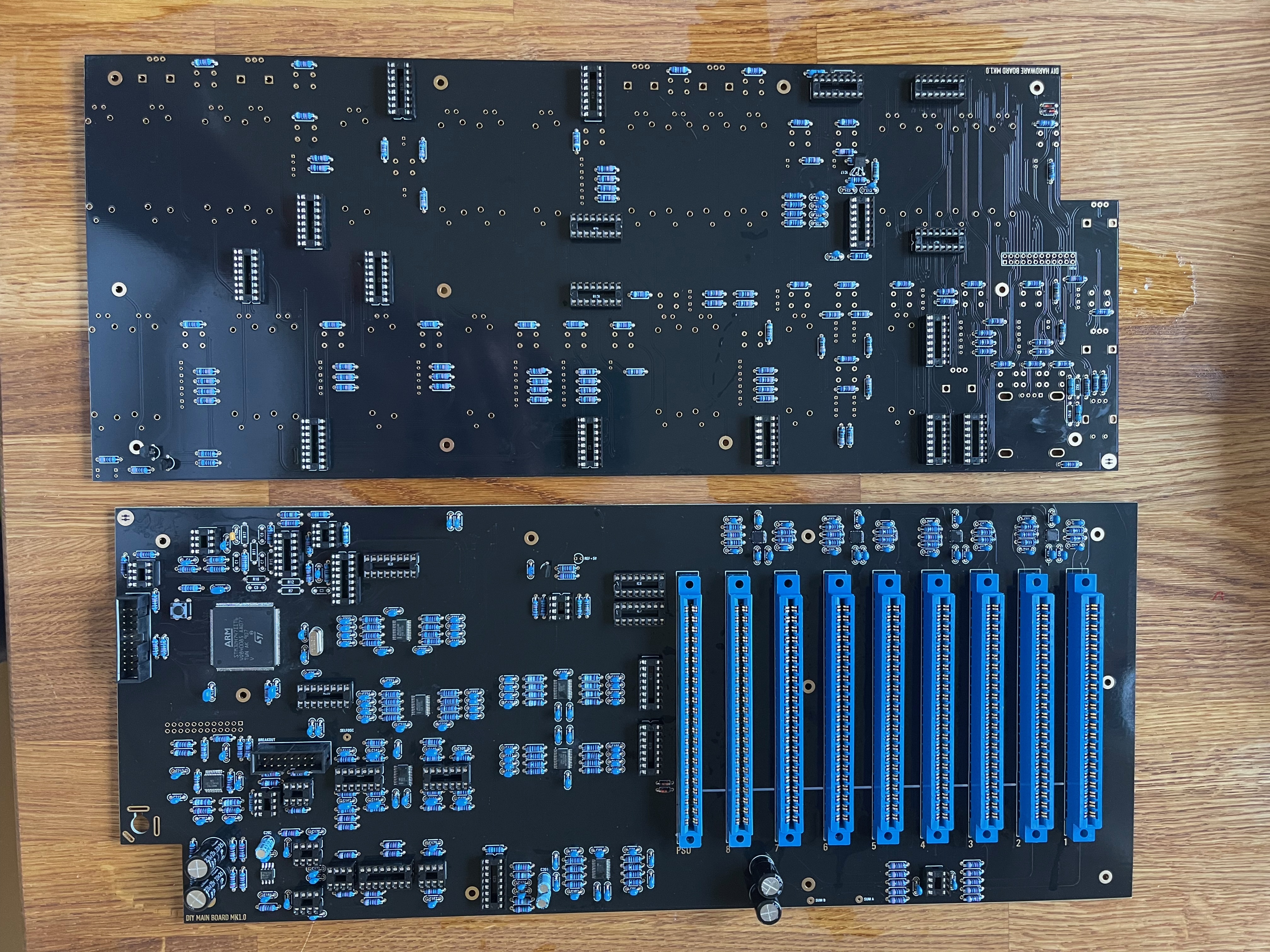
- install the ICs
- Double and triple check the IC orientation ( tip: mark with a pen all ICs which did you checked)
do not install the 10pin headers/pins yet (we put the header on the pcb later - when we have finished the controlboard - to get the best alignment)
do not install the OLED yet - to avoid damages and dust on the screen
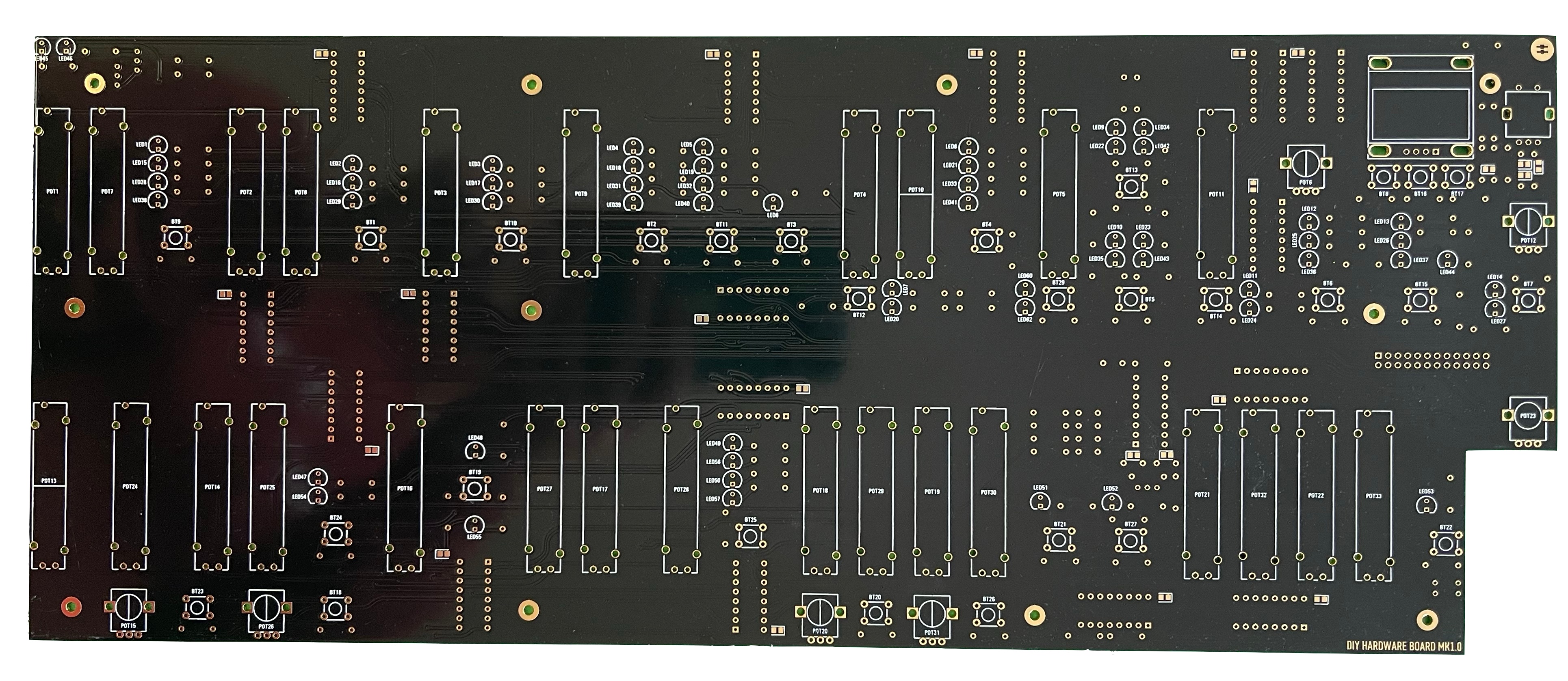
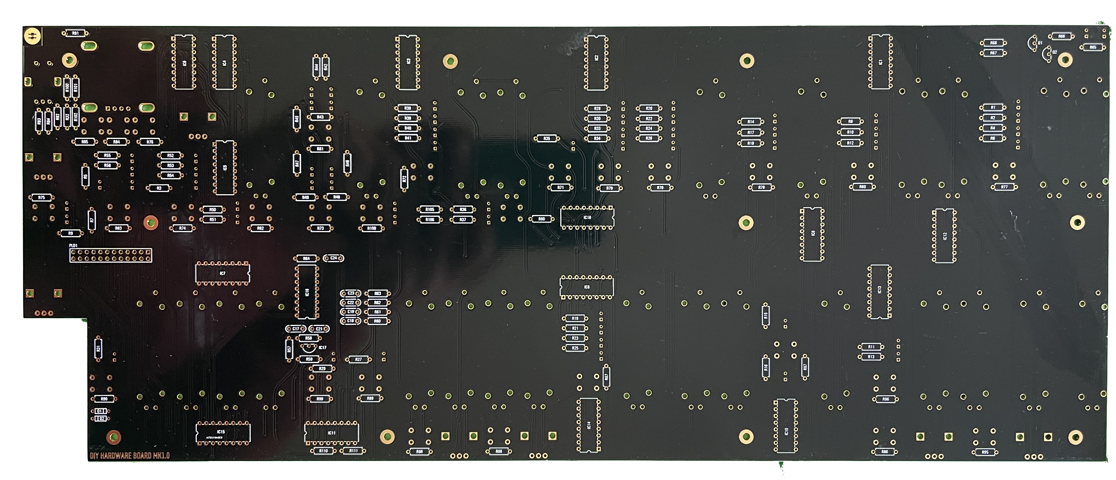
Hardware Board (HB) (sometimes called Controlboard)
- we start with the PCB side with the IC sockets, the rear-side which is connected to the Mainboard (as shown in my pictures)
- install the SMT capacitors as before described in the Breakoutboard section.
- install the resistors - solder all pins.
- install the ceramic capacitors - solder all pins
- install the IC sockets - standard IC sockets preferred - solder all pins after you have checked the alignment
- install the transistors - do not overheat the pins here
- wash the pcb carefully with isopropyl and soap with handwarm water up to 50C Celsius.
- Install all ICs when the pcbs are dry
- double and triple check the IC orientation ( tip: mark with a pen all ICs which did you checked)
do not install the OLED yet - to avoid damages and dust on the screen
do not install the headers /pins yet
do not install the LEDs yet, no sliders , no potentiometers for now !!
because you have to clean/wash the PCBs PCBs before we can proceed - jump to Voicecard assembly until the pcbs are dry. (normally overnight in a warm room)
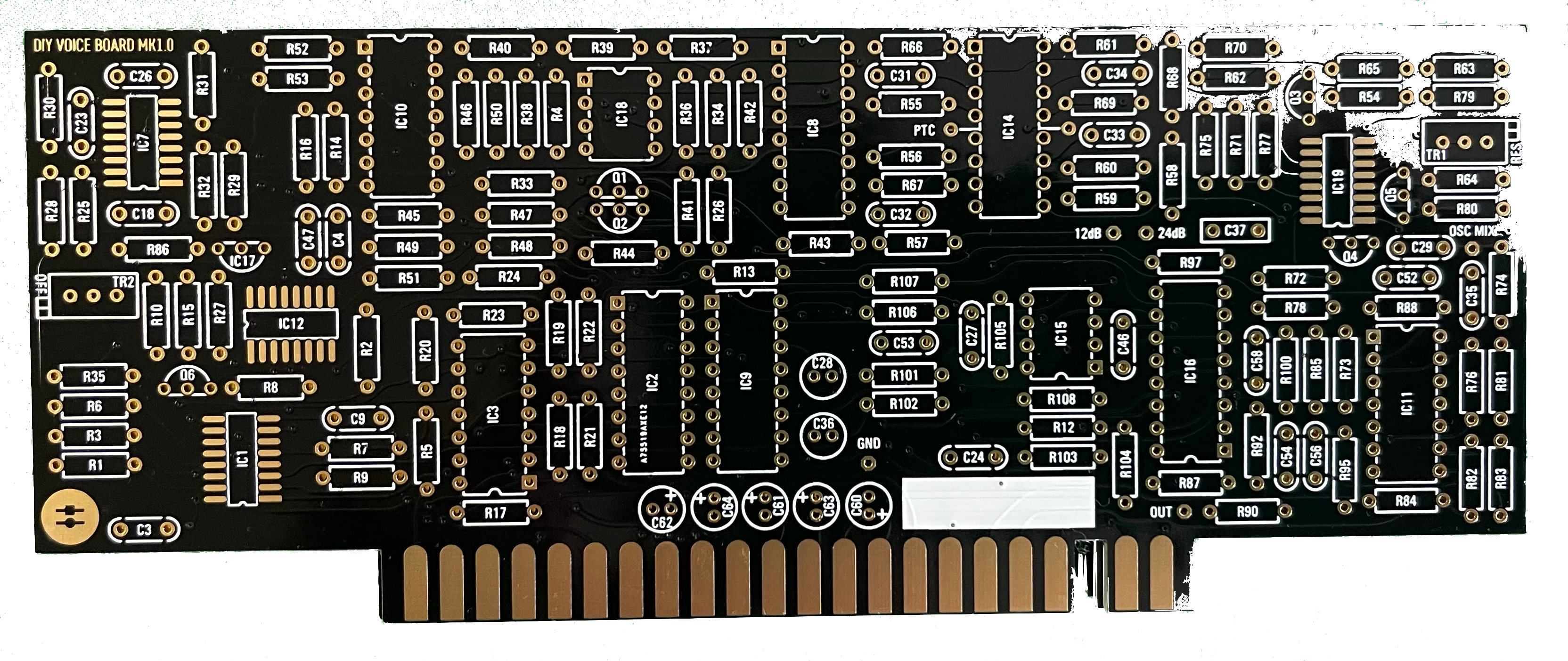
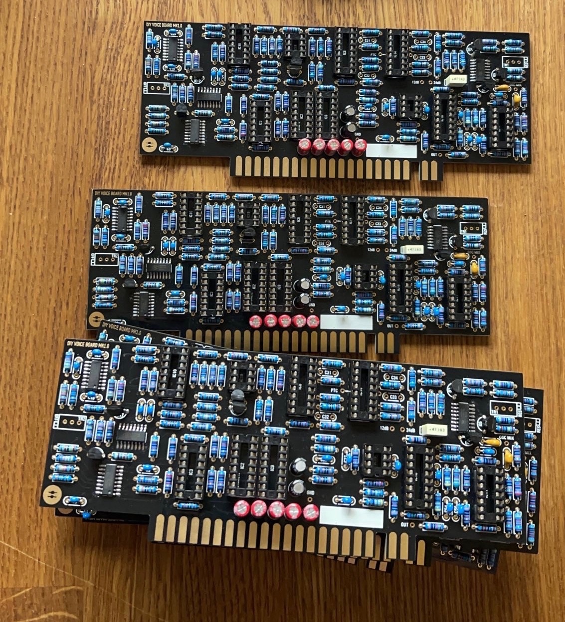
Voicecards:
assemble the voices until the other pcbs are dry - do not install the trimmers until you have washed the PCBs!
- install the SMT capacitors as before described in the Breakoutboard section.
- install the SMT ICs
- install the resistors - solder all pins, do not install the Tempco Resistor yet
- install the ceramic capacitors - solder all pins
- install the IC sockets - standard IC sockets preferred - solder all pins after you have checked the alignment
- install the Transistors/regulators - do not overheat the pins here
- look in my above guide - about the 240pf capacitors - maybe you have to select or match something - its not needed but for some builders just a notice
- install the Filmcapacitors/Electrolyte caps and solder one pin - align the capacitors before you solder the second pins.
- wash the pcbs as described before
- when the pcbs are dry - install the Trimmers
- install all ICS
- install the Tempco resistors - this must be thermal connected, use thermal paste
- double and triple check the IC orientation
Hardwareboard part 2:
install the 12mm spacer on the HW.board, then install the 10pin dual row header/socket - solder both parts to each pcb, clean these solderpoints with eartips carefully.
...