...
you need an ESD map and ESD safe handling (tools) - because the uController is preinstalled and can be destroyed due to wrong handeling
do not install the 10pin headers/pins yet (we put the header on the pcb later - when we have finished the controlboard - to get the best alignment)
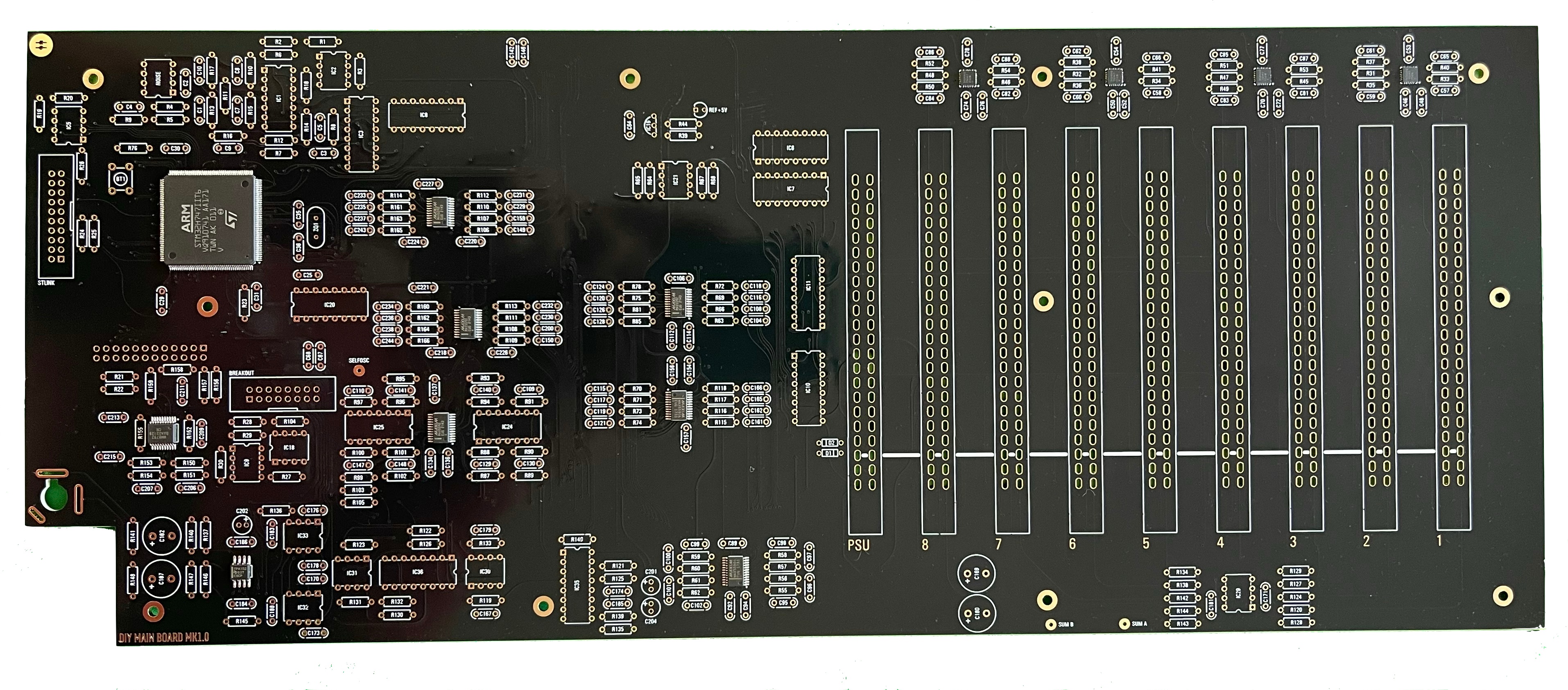
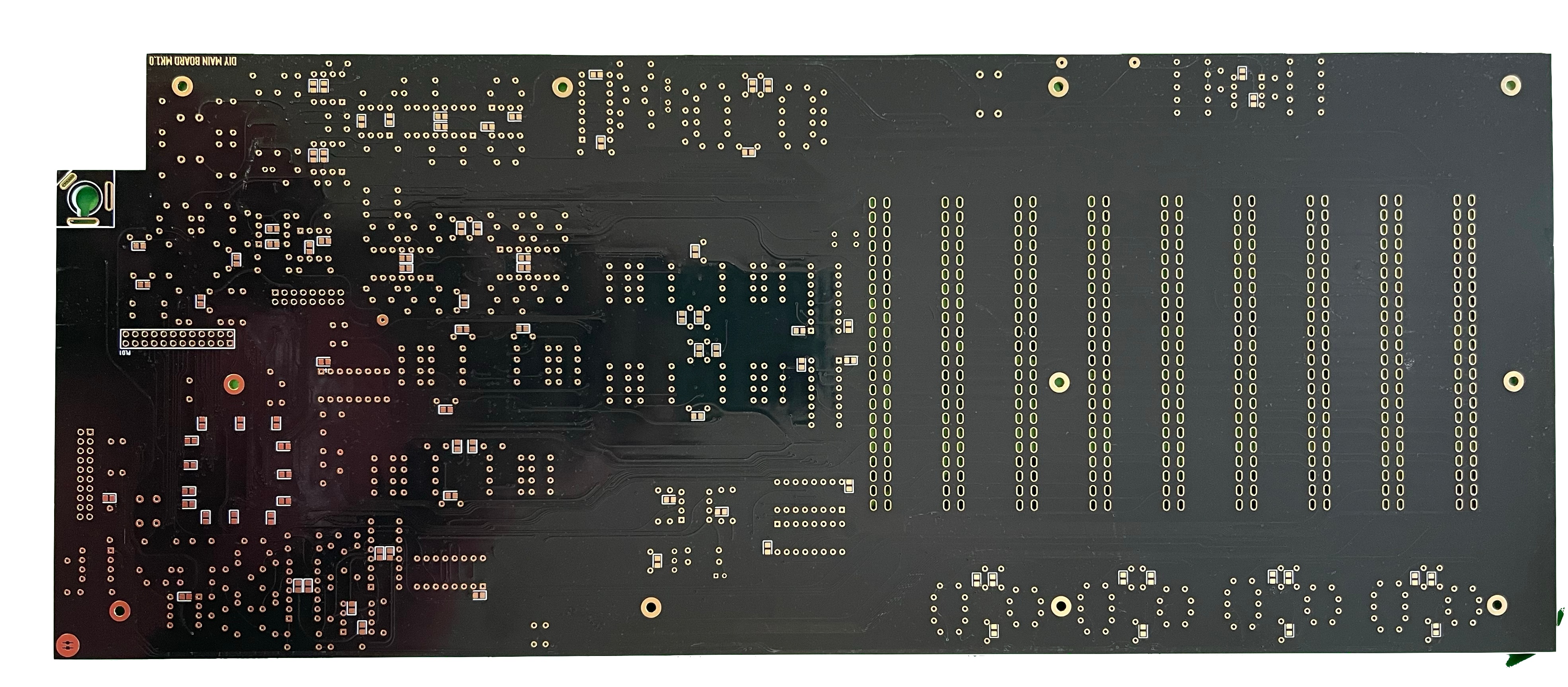
check the soldering on the EDGE card pins carefully for shorts/solder bridges.
...
handling.
I really prefer to use a Soldering frame - Ideal Teck PCSA-4 (the MB and HB-pcb fits perfect)
- install the SMT capacitors as before described in the Breakoutboard section.
- install the resistors - solder all pins.
- install the ceramic capacitors - solder all pins
- install the IC sockets - standard IC sockets preferred - solder all pins after you have checked the alignment
- install the quartz - do not overheat the pins here
- install the Filmcapacitors/Electrolyte caps and solder one pin - align the capacitors before you solder the second pins.
- install the EDGE connectors - solder only at top and bottom a pin and check the alignment, solder from left to right to minimize overheat problems with the connectors.
- don't forget to solder bridges at the white flat line on the EDGE cards as shown in the above table.
- check the soldering on the EDGE card pins carefully for shorts/solder bridges.
- wash/clean the pcbs carefully with respect on ESD safe handling
do not install the 10pin headers/pins yet (we put the header on the pcb later - when we have finished the controlboard - to get the best alignment)
do not install the OLED yet - to avoid damages and dust on the screen carefully
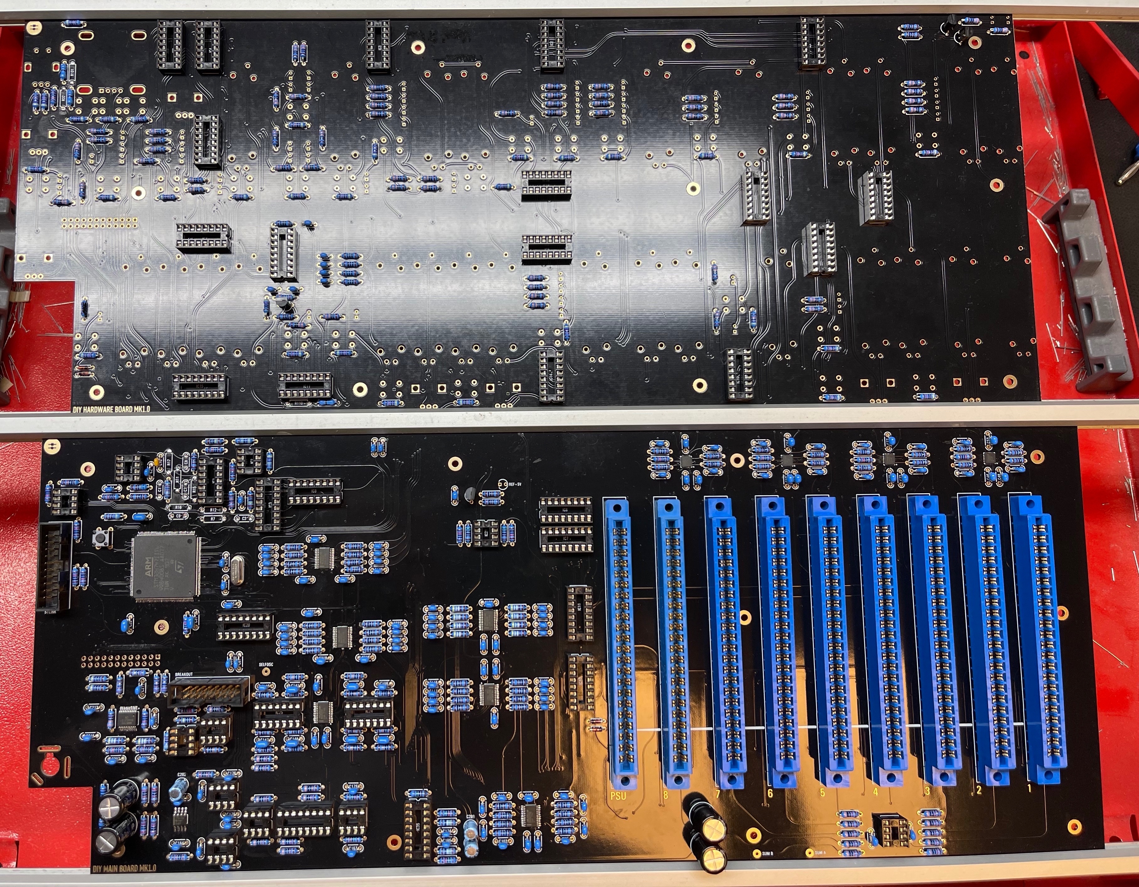
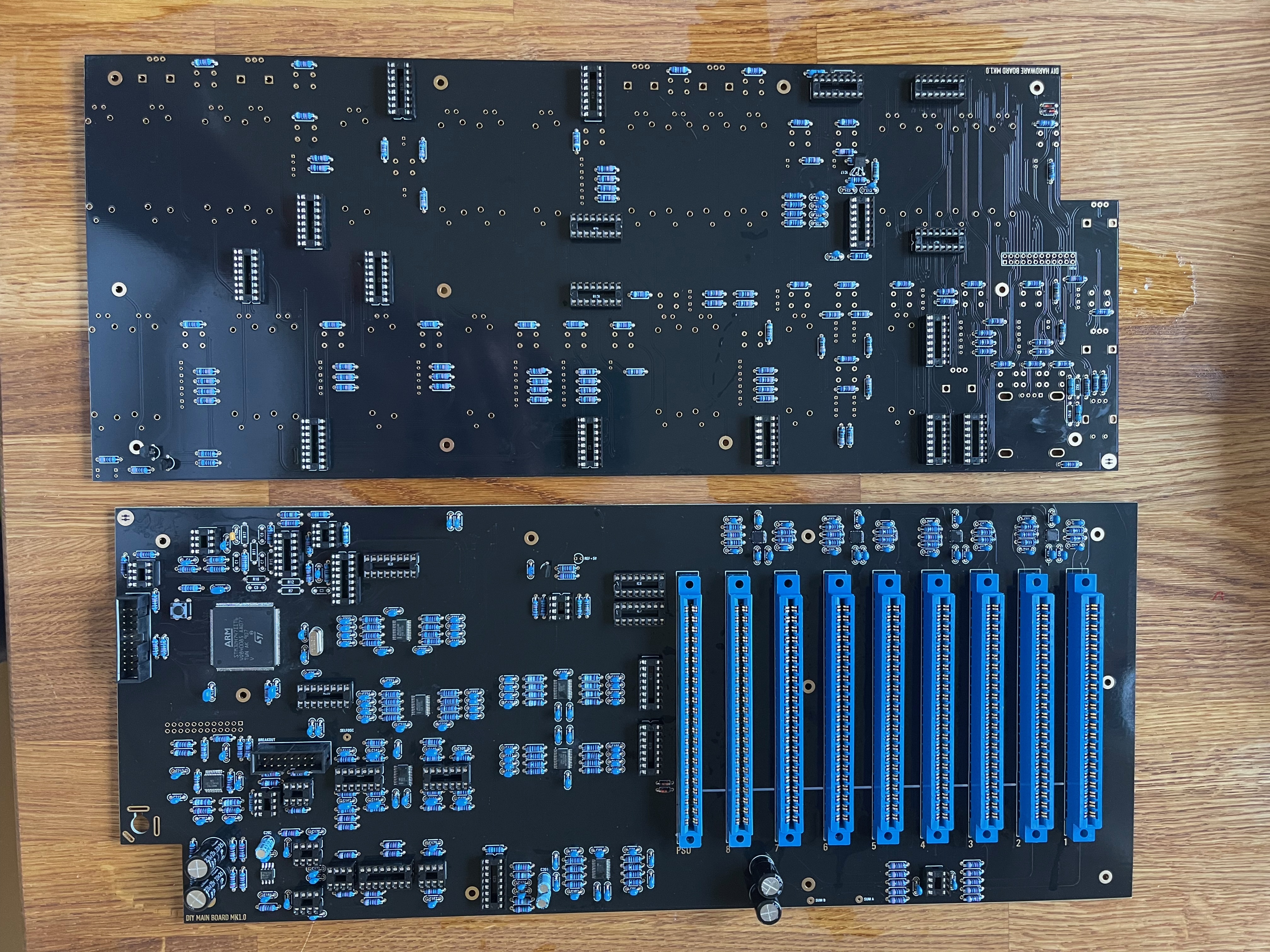
Hardware Board (HB) (sometimes called Controlboard)
...