e
| Panel | ||||||||||
|---|---|---|---|---|---|---|---|---|---|---|
| ||||||||||
Projecttitel: ISE-NINStatus:
Startdate: 26th Aug.2022Duedate: 15th Sep.2022Manufacture link: https://black-corporation.comModwiggler: https://www.modwiggler.com/forum/viewtopic.php?t=265268Facebook Build Group: https://www.facebook.com/groups/517757979447099Facebook User Group: https://www.facebook.com/groups/800008500661600 |
...
Date | Location | Type | Issue | Tip | |
|---|---|---|---|---|---|
| 13. Aug.2022 | Hardware Board | INFO | minimize Slider/Potentiometer malfunctions Soldering Info | when you install the sliders, DO NOT solder all pins successively, solder only one pin at the top and the bottom and proceed to the next slider, when you have installed all of them - solder the next single pin of each slider. this has to be respected with potentiometers too. The Sliders and Potentiometers have lubrication inside which is sensitive to heat and can be easily damaged (this mistake was made in many Syncussion clones ) | |
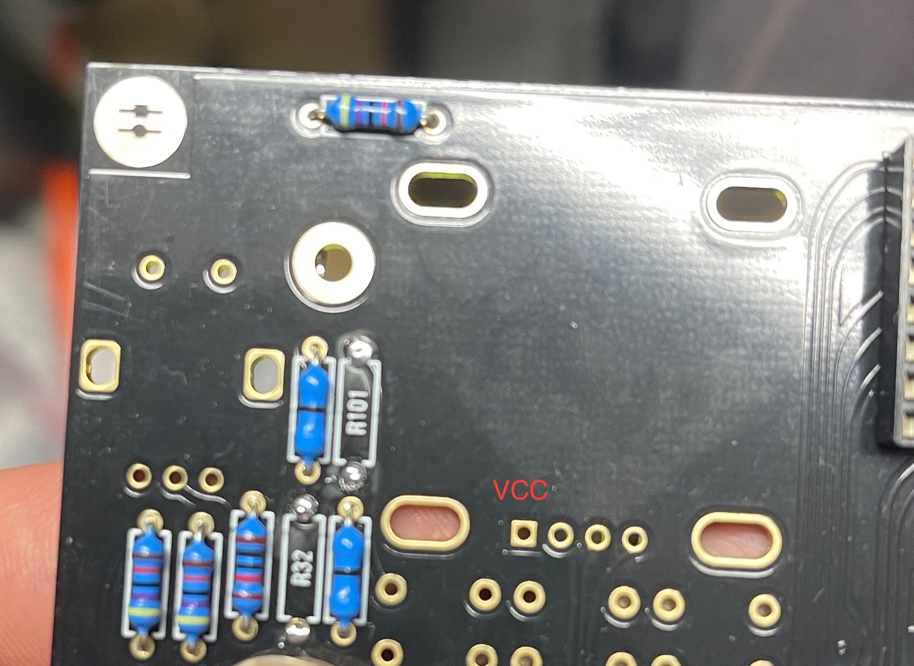
| 13. Aug.2022 | Hardware Board | INFO | OLED Selection and R101/R32 - R100/R102
| when you have an OLED with the PINOUT: VCC-GND-SCL-SDA install R100 and R102 (0 Ohm - a bridge) (R32/R101 must be left empty) in case you have an OLED with the PINOUT: GND-VCC-SCL-SDA install R101 and R32 (0 Ohm -a bridge) | |
| 13. Aug. 2022 | All pcbs | INFO | some IC Sockets do not point in the same direction as the others, it´s a known issue that people install ICs backwards | Double and triple check every IC orientation - maybe 80% of all device malfunctions happen because of that and often end in very expensive repairs | |
| 13. Aug.2022 | Hardware Board, PSU, Mainboard | INFO | the LEDs do not work | when you build the device - its important to start with the power supply - here you can test the LED orientation. never trust the vendor pinout for LEDs. normally the long LED leg is the positive end (anode) (but some circuits are powered from negative rails and GND is the positive end in this case- just as an explanation) | |
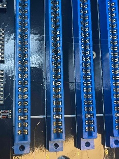
| 13. Aug. 2022 | Mainboard | INFO | solder the pins on the Edgecard holder where you find the white stripe on the PCB -
| you can't install the edge cards in the wrong way | |
| 14.Aug.2022 | Mainboard | INFO | keep the length of the power cable as short as possible - that minimizes the risk that you accidentally put the PSU card in a voice card slot | ||
| 14.Aug.2022 | Hardware Board | INFO | pay attention to "Pot23 - Volume" (upper right corner) this is the one non-center detent pot. | ||
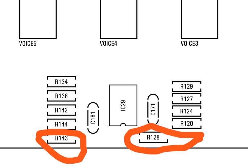
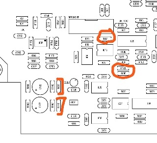
| 14.Aug.2022 | Mainboard | BUG | BOM1.0 Change- fixed in BOM v1.0.1 R103, R104, R105 = 330K (was 30k in BOM rev 1.0.0) R128, R143 = 10K (was 30k in BOM rev1.0.0) R137, R146 = 10K. (was 20k in BOM rev1.0.0)
| fixed on 24.Sep.2022 in BOM 1.0.1 |
Build guide: ( in progress)
Power supply PCB (PSUb) -
...