...
Date | Location | Identified Issue | Resolution | update |
|---|---|---|---|---|
| May 29, 2018 | BOM hw board | R119, R120, R121 not in BOm 1.02 | R119 4K7 R120 100R R121 2K2 | BOM project updated-1June2019 |
| May2019 | OLED DISPLAY | Double check the OLED pinout | rin case of wrong pinout - remove 2 oled pinheader pins and use a resistor leg and cable tube shrink correct is: VCC-GND-SCL-SDA | |
| BAT43 x2 missing D3 D4 on Harware board | BOM project updated-1June2019 | |||
| 12 Jun2019 | BOM hw board | C34 missing in BOM | 560pf mlcc RM5 | |
| 30 July 2019 | Controlboard | dont install a Metal spacer between controlboard and mainboard in the middle of the pcb - otherwise it touch the card slot adapter pins
| use only the short 7mm spacer and a screw/nut from rear. | |
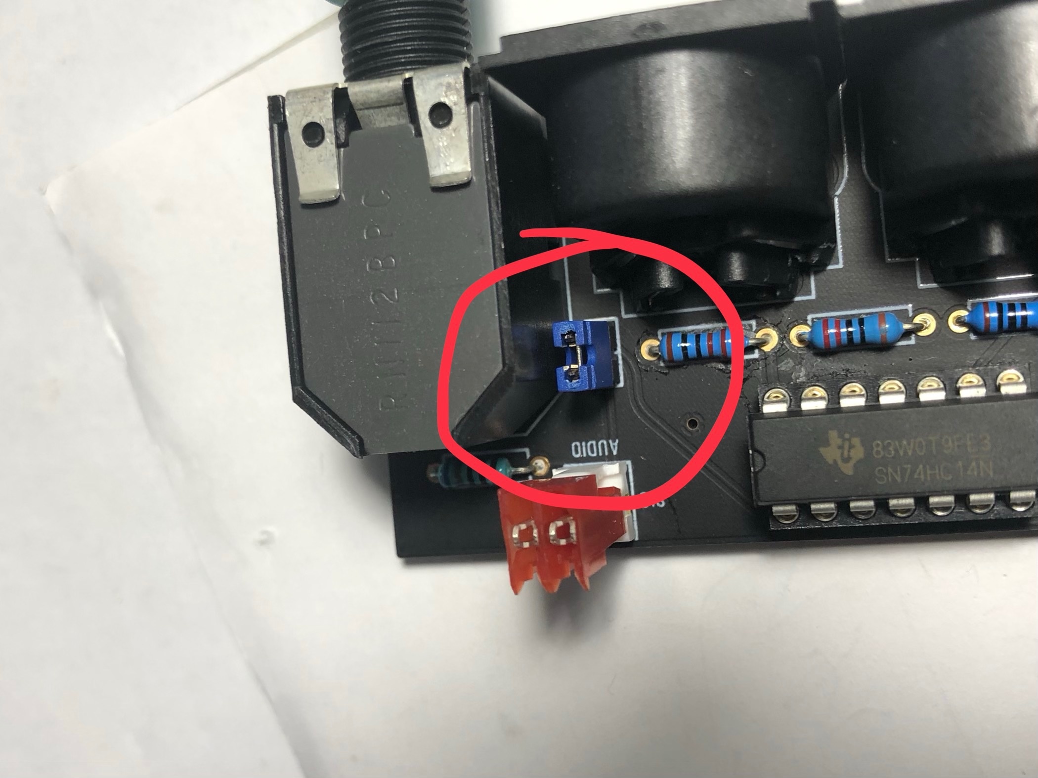
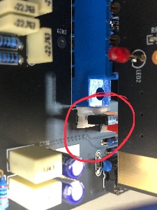
| 30 July | Audio output | install on both locations a 2pin header to optionally install a PC jumper. if you use the flat ribbon cable for the audio signal you have to bridge the pins with a jumper. when you use the MTA100 headers with coax cable, dont install the jumpers ! Connect only at the mainboard side (MTA100 header)the ground of your shielded cable. Don’t connect the GND at the MTA100 header at the breakoutboard or you get a groundloop (more noise, risk of hum) |
| |
| 30 July 2019 | info | use a 24V Center positive Powersupply with 2Ampere or more | don't use the 12V PSU from DDRM DIY Version. | |
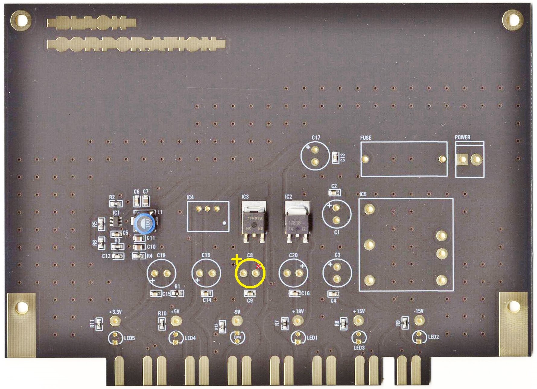
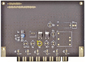
| 1 Aug 2019 | major bug | on the PSU card is the -9V Capacitor silkscreen wrong, this was happen on my PSU card and the capacitor leaked, thx to Ando for the picture. | install the positive pin of C8 on the left side (as shown in the bottom picture)
| reported to Roman and Bob |
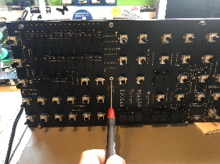
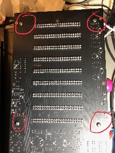
| 15 Aug. 2019 | mainboard | mounting holes for brackets do not fit with the Mouser screws. carefully drill a bigger hole as shown here: (marked) only this 4 holes |
| |
| 15 Aug | PSU | the fuse must be around 1.2Ampere, the current of the kijimi on 24V DC is 950mA | ||
| August 2019 | Voices | improve the sound (from Roma.F - the developer) | Voicecard: replace R108 from 10K to 20K replace R111, R52 from 91K to 20K replace R38, R97 from 330K to 576K (i used a 560K plus a 20K resistor in series which was measured to 575k (1% resistors) (only 576K when you want TL074 for IC2 and IC9 otherwise use 330k) remove R60 , R119 (220R) → not installed replace IC2 and IC9 from TL064 to TL074 | |
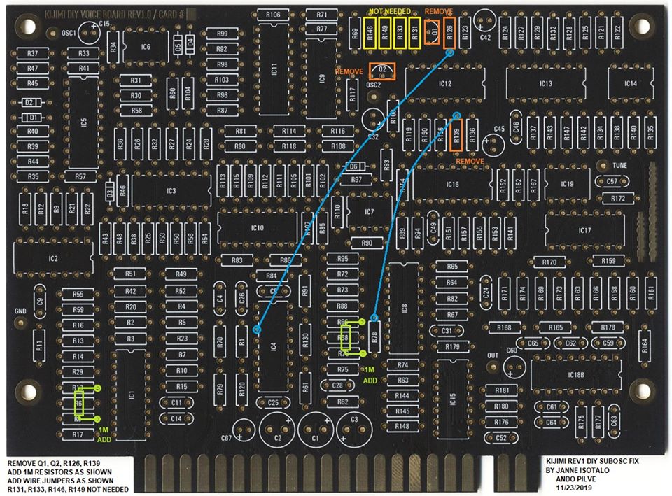
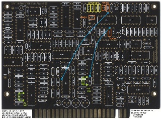
| January 2020 | Voices | fix the Subosc. Problem (glitches and artifacts) | Here is the SUBOSC fix Janne and I worked out. Details below: the addional parts are not included in the BOM (16x 1M resistor) (click to enlarge)
1. Remove these components: Q1, Q2, R126, R139 2. Add two 1M resistors as shown (to PCB solder side) 3. Add two jumper wires as shown (to PCB solder side) 4. R131, R133, R146, and R149 are not needed. If you already have them installed, no need to remove them (they don't do anything). If you are starting to build, don't install them. NOTES: This fix is for DIY REV1 KIJIMI only. Prebuilt Kijimi does not have this issue. You can omit all these highlighted parts and test your voice card without the SUBOSC feature. Everything else should still work. When modifying your voice card, do the modification on one card first and then test for any glitches (there shouldn't be any). Then modify the others. Please report back if you have any issues. Thanks to Janne for the hard work in helping to test and develop this fix. Technically this mod disconnects the saw waveform and routes the pulse waveform instead into the 4013 divider. The 1M resistors enhance the rise and fall time of the pulse waveform. The original problem was caused by transient noise on the saw waveform that triggered the 4013 divider. | thanks to Janne and Ando |


...
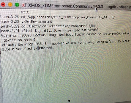
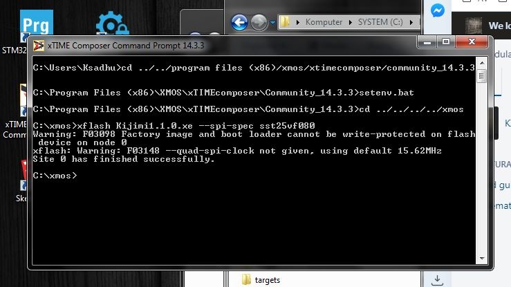
message, after further seconds the terminal shows you some memory addresses which are written, and then: finished successfully, on the KIJIMI the OLED Display must show you some graphics (PNL mode etc)

Here´s a Video from me about the Firmware Installation:
...
Now the Kijimi is programmed and ready for calibration.
Calibration
...