...
At this hole : DO NOT mount at the rearside a 12mm spacer, only use at top side a 5-6mm spacer and from rear a screw/nut (depends on what you have on hand) otherwise a 12mm spacer will short the voice card slot pins
POTIS:
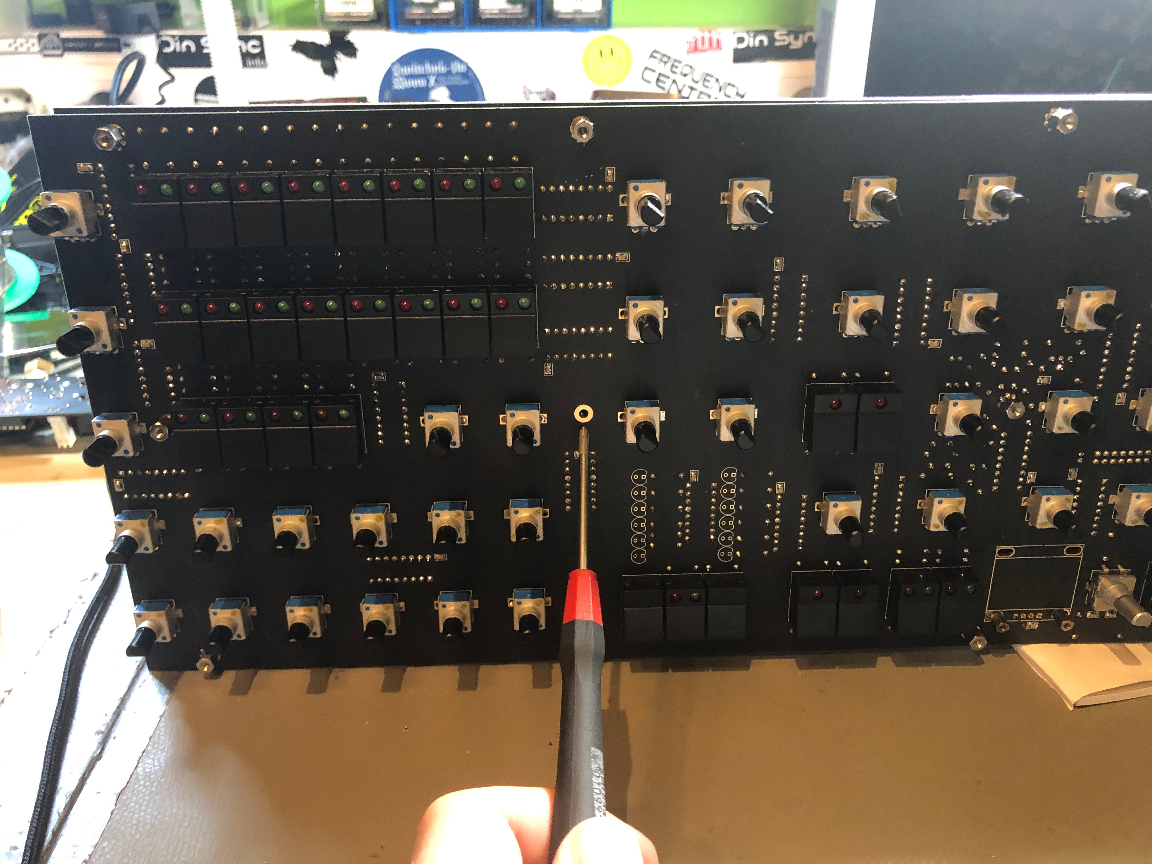
install all potis and solder only one pin, then check the orientation of all pots in a row - maybe you have to change the alignment.. solder a groundpad and check the orientation again.
...
Date | Location | Identified Issue | Resolution | update |
|---|---|---|---|---|
| May 29, 2018 | BOM hw board | R119, R120, R121 not in BOm 1.02 | R119 4K7 R120 100R R121 2K2 | BOM project updated-1June2019 |
| May2019 | OLED DISPLAY | Double check the OLED pinout | rin case of wrong pinout - remove 2 oled pinheader pins and use a resistor leg and cable tube shrink correct is: VCC-GND-SCL-SDA | |
| BAT43 x2 missing D3 D4 on Harware board | BOM project updated-1June2019 | |||
| 12 Jun2019 | BOM hw board | C34 missing in BOM | 560pf mlcc RM5 | |
| 30 July 2019 | Controlboard | dont install a Metal spacer between controlboard and mainboard in the middle of the pcb - otherwise it touch the card slot adapter pins
| use only the short 7mm spacer and a screw/nut from rear. | |
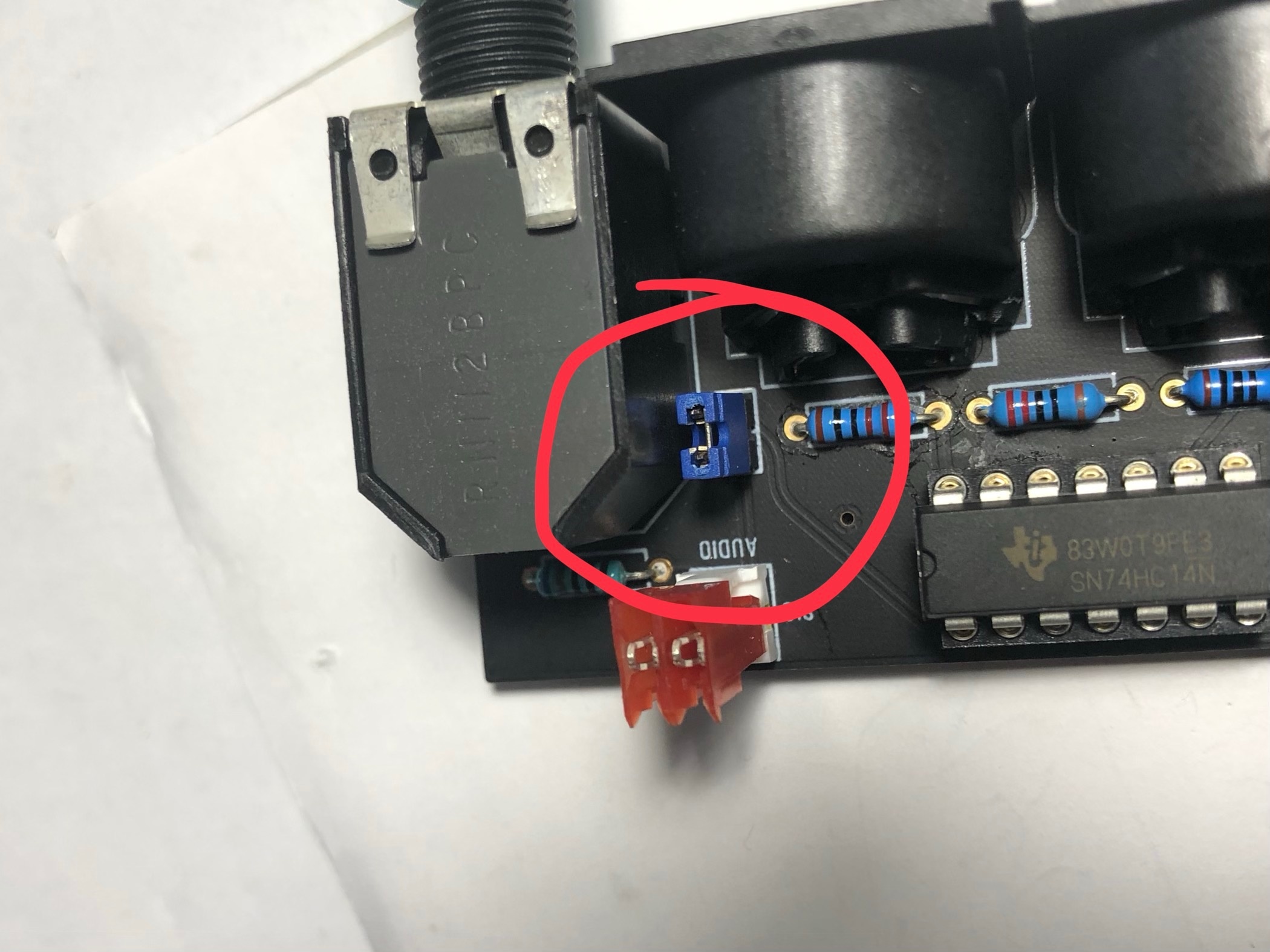
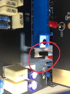
| 30 July | Audio output | install on both locations a jumper (bridge both pins) if you use the flat ribbon cable for the audio signal too. when you use the MTA100 headers with coax cable, dont install the jumpers. only connected at the mainboard side the ground, dont connect the GND at the breadboard MTA header - or you get a groundloop (more noise, risk of hum) |
| |
| 30 July 2019 | info | use a 24V Center positive Powersupply with 2Ampere or more | don't use the 12V PSU from DDRM DIY Version. | |
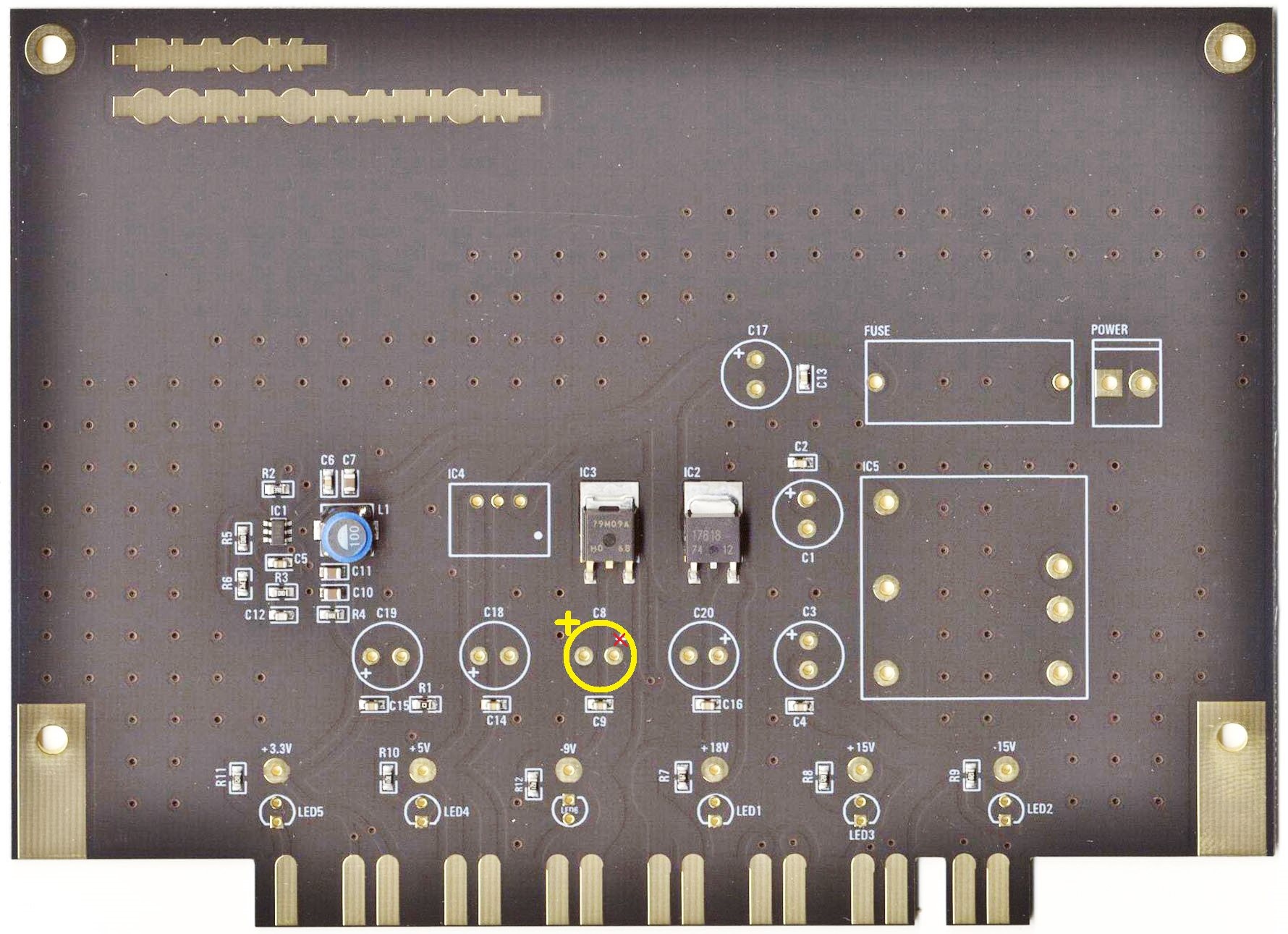
| 1 Aug 2019 | major bug | on the PSU card is the -9V Capacitor silkscreen wrong, this was happen on my PSU card and the capacitor leaked, thx to Ando for the picture. | install the positive pin of C8 on the left side (as shown in the bottom picture)
| reported to Roman and Bob |
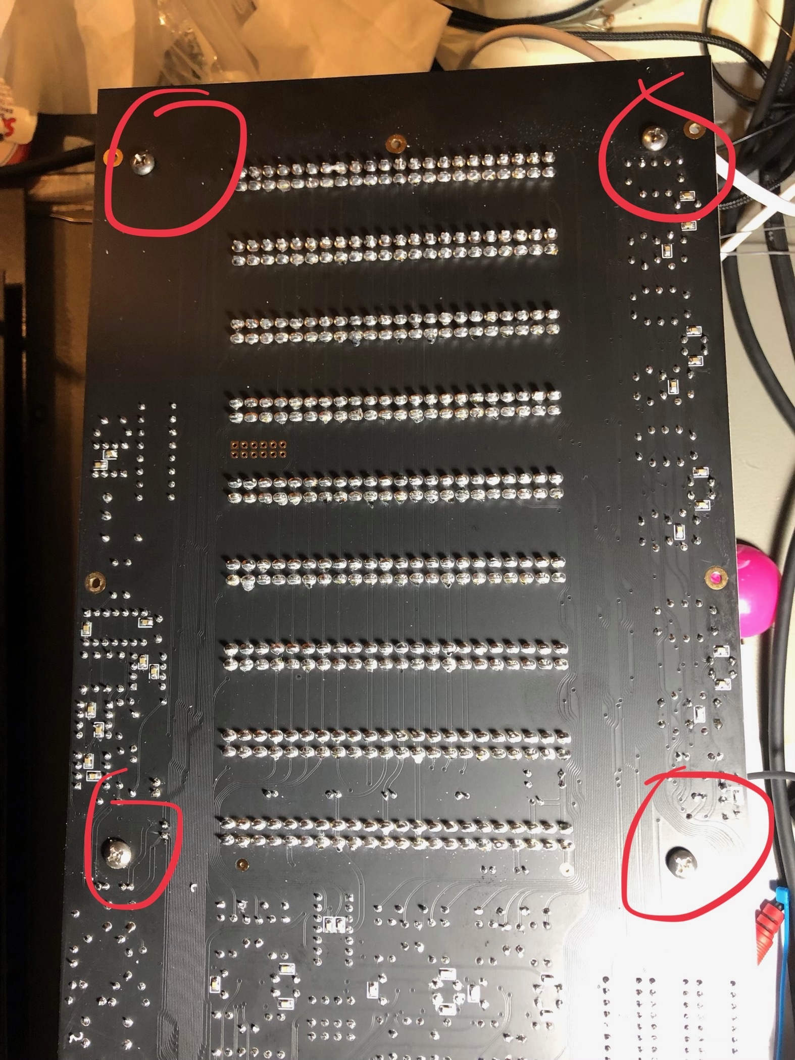
| 15 Aug. 2019 | mainboard | mounting holes for brackets do not fit with the Mouser screws. carefully drill a bigger hole as shown here: (marked) only this 4 holes |
| |
| 15 Aug | PSU | the fuse must be around 1.2Ampere, the current of the kijimi on 24V DC is 950mA | ||
| August 2019 | Voices | improve the sound (from Roma.F - the developer) | Voicecard: replace R108 from 10K to 20K replace R111, R52 from 91K to 20K replace R38, R97 from 330K to 576K (i used a 560K plus a 20K resistor in series which was measured to 575k (1% resistors) (only used when you want TL064 for IC2 and IC9 otherwise use 330k) remove R60 , R119 (220R) → not installed replace IC2 and IC9 from TL064 to TL074 |
| Gallery | ||
|---|---|---|
|
...