Successful Build : 04/2019
it adds an envelope controllable Ring Modulator, Chorus, Tremolo, Delay, and Reverb effects. It is designed to work seamlessly with Deckard’s Dream, but it also works as a standalone audio effects device. |
Schematics:
DD-EXPANDER-SCHEMATICS-REV1.zip for rev.1.0
BOM:
DD-EXP-BOM-REV1.0.1.pdf latest version for rev.1.0 and YOU MUST ADD 2x TL071 and 1x 4.7uF MLCC capacitor RM5DD-EXP-BOM-REV1.0.0.xlsx (Old version) for rev.1.0
the new PCB Version is 1.1 !! (midi noise fixed) it use following changes which affect the above BOM, you have to respect this: IC33 and IC37 is TL071 (DIP8) C166 not in BOM 4.7uF ceramic (MLCC) RM5 |
DDRM Expander VC Placement Guide V2 from Kevin Looney:
DDRM Expander VC Placement Guide V2.pdf
DDRM FAQ and Build tipps from Todd
Deckard’s Dream Expander FAQ and Build Guide V1-7.docx
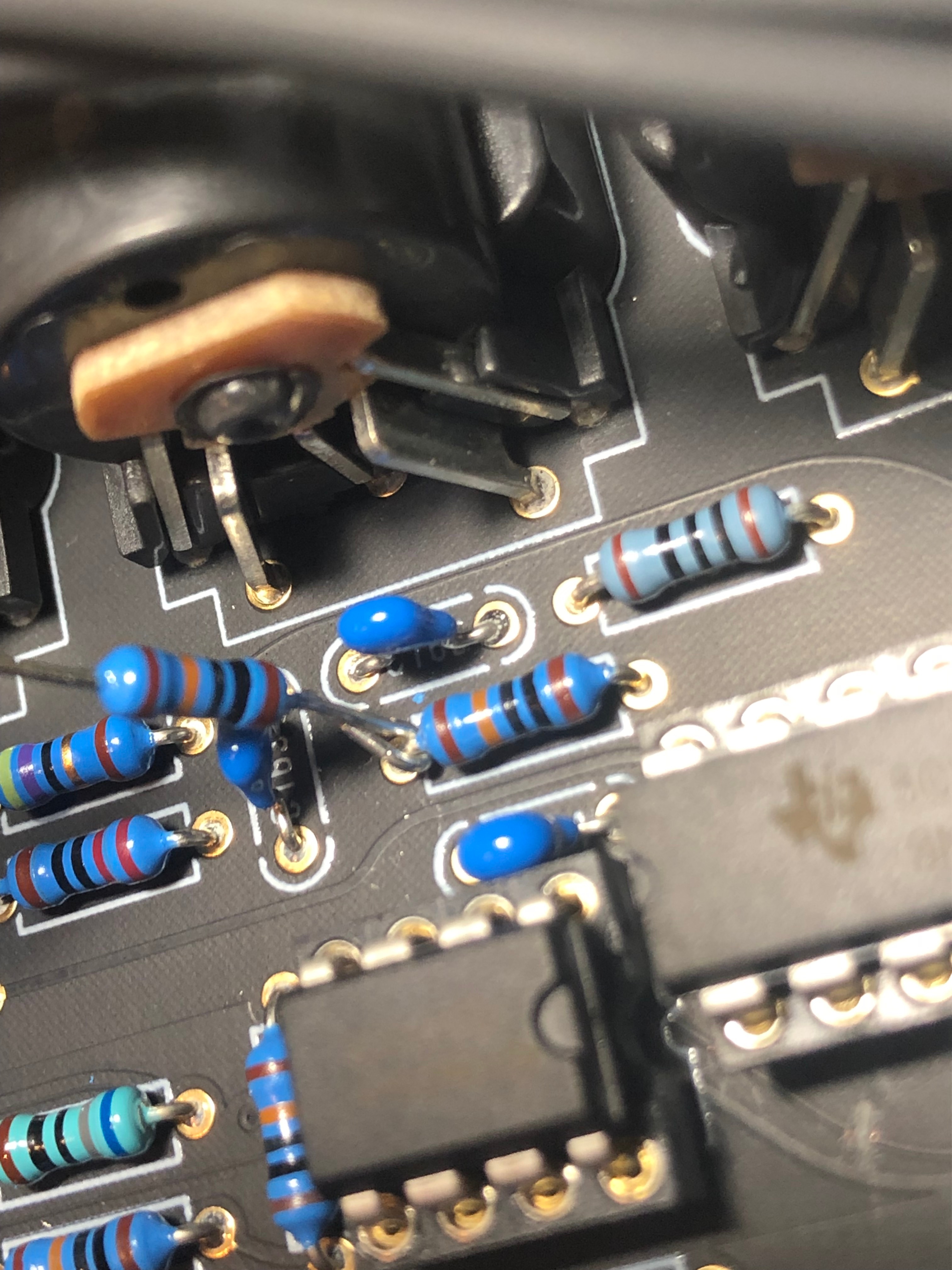
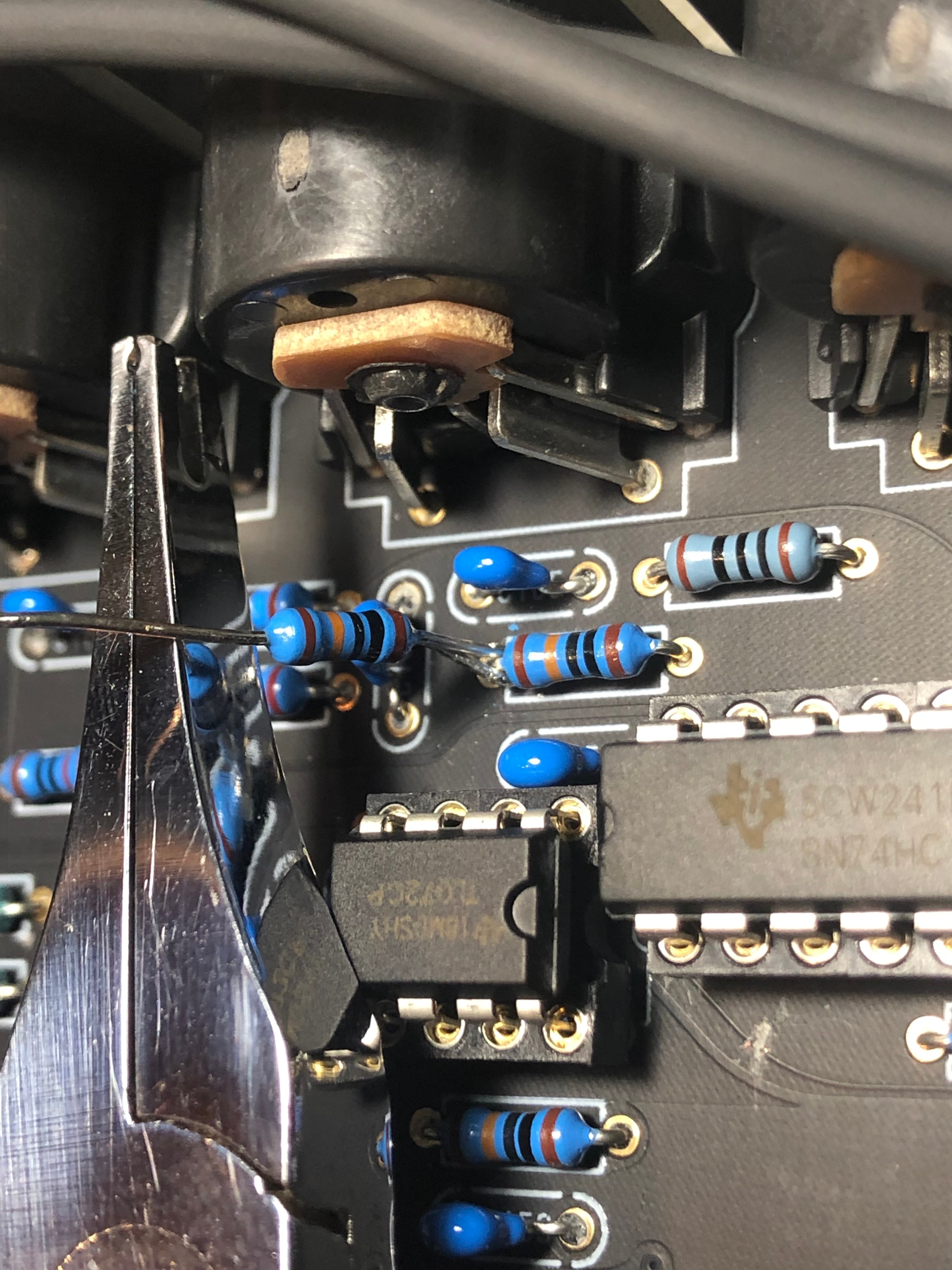
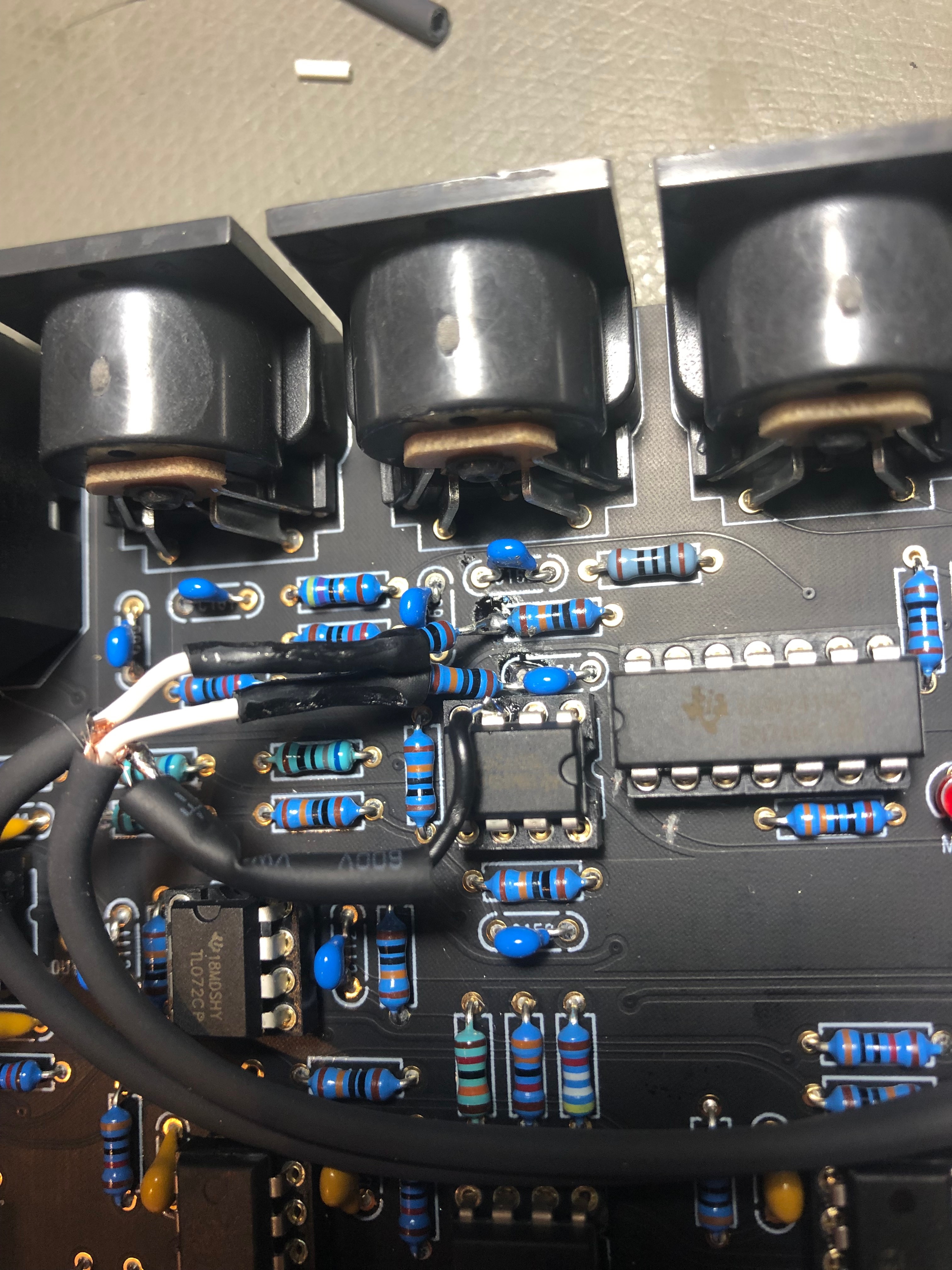
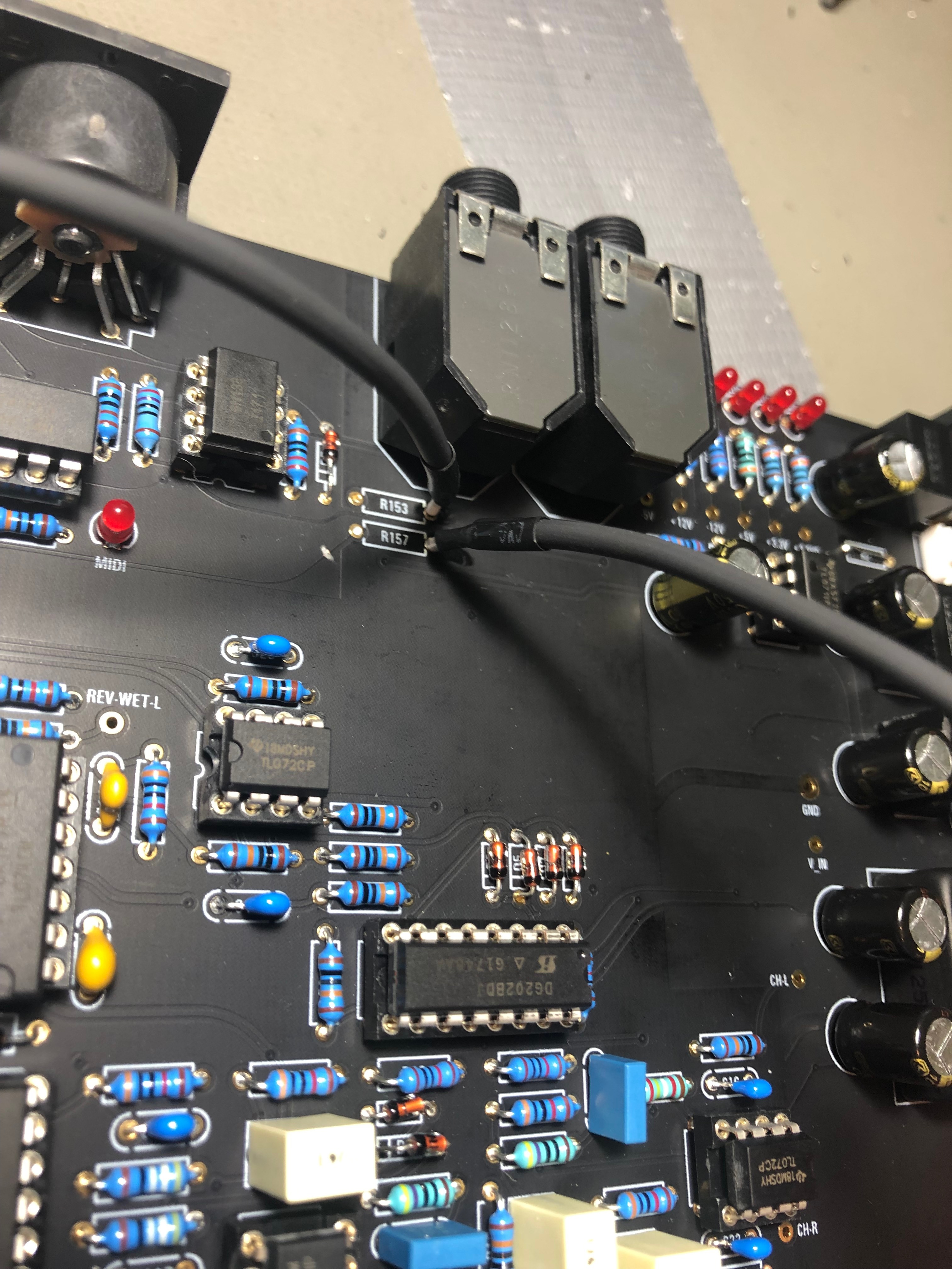
MIDI-NOISE FIX pictures:
only for DIY PCB Version 1.0
is fixed in DIY PCB Version 1.1
If you want a fix of your factory assembled Version, contact me
Click expand for Pictures from rev1.0 pcb Modification FIX
   |
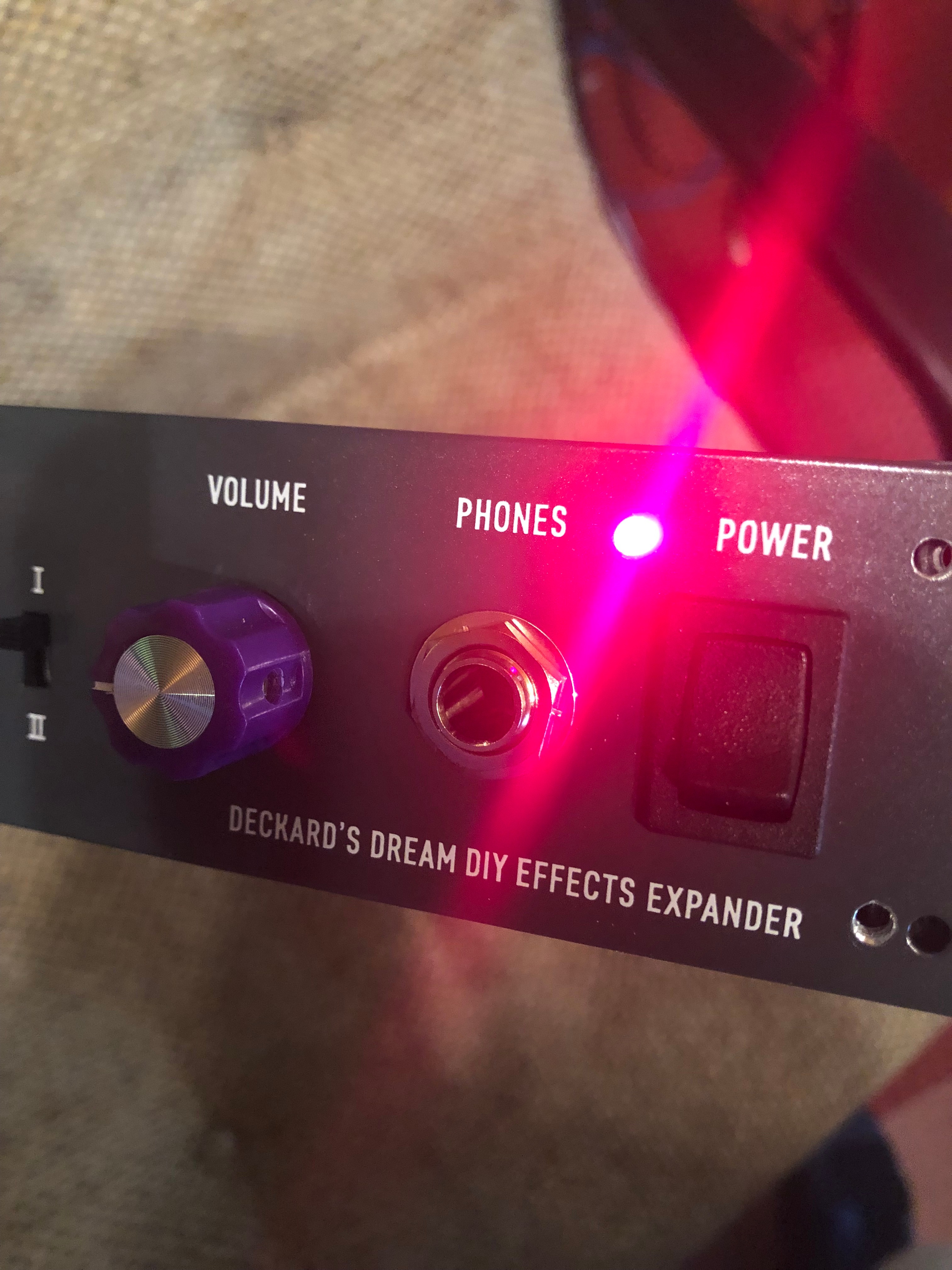
Power LED Installation:
remove the 12V LED from the Card PCB and drill a 4,5mm hole in the frontpanel - which is the standard size for 3mm LED-holders (available in most electronic shops)
psu DC-DC alternative part:
DKMW30F-12 meanwell (approval - tested
)
The DSP chip, potentiometer, AS3310, As3340 from Musikding too confirmed
Case: 169 USD
First Design Concept:

Final:
