Project
Projecttitel: Arp 2612 Filter
Status: FINISHED
Startdate: 21.October 2014
Duedate: 28.October.2014
Manufacture link: steffcorp.se
Muffwiggler link: http://www.muffwiggler.com/forum/viewtopic.php?t=121124&postdays=0&postorder=desc&start=80
the Filter sounds very good - one of the best Filter i heard (MOTM440, MOTM480 too)
Building guide: 2612_BuildDoc.pdf
i go forward to use a 2n3958 like the original instead of 2x2n5459, in building guide " there are markings for usage of 2n3958"
Parts/BOM (listed only non standard parts)
pcb (control and main pcb from steffcorp
1x tempco 1k87 (i used a 3500ppm KRL, check thonk.co.uk and synthcube.com )
2x 1n5817
1x LM301AN or LM301AH
4x 3k32 (3k3 works fine too)
1x 23k2 (Tip: check cermet 22k for tolerances ![]()
1x 196k
2x 250R trimpot multiturn or 500R trimmer
1x 10k trimpot multiturn
1x 100k trimpot multiturn
Panel 4072 panel from Bridechamber.com, you can add the finetune on the pcb /the 4072 bridechamber panel dont have a finetune pot
2x 100k lin bourns pot (frequenncy, resonance) - prefered due to handling
2x 100k log Bourns pot (input1, input2) usage of alpha/alps are fine too
2x 100k pot for CV
Building:
all 2N3904/2N3906 was matched by me within 1mV
a pair 2N5459 was matched too
resistors, caps, sockets, transistors was stuffed by me, pcb washed, all trimmer and ics added later,
for MOTM conversion: make sure you connect both pcb in correct way !!
wiring of jacks: make sure you connect for CV1-CV2-v/oct the jackswitch to the pcb.
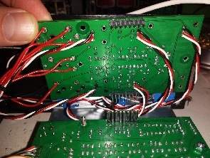
i used shielded cables (RG174) for input/output jack
calibration: see build document and double check it , in my case was the gain and offset related to the initfrequency at beginning.
V/oct calibration result was not perfect but better as some other filters i have build in last years.
Description
copy from https://steffcorp.se/product/2612/
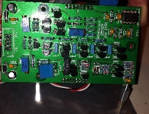
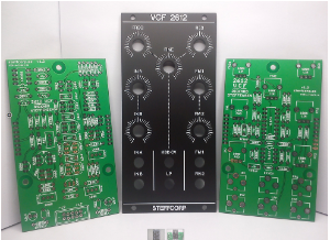
This is a clone of the 4012 VCF used in the ARP 2600.
Other than some substituted parts and a “sandwich-layout” mainly adjusted for the eurorack standard, I have tried to keep all the original quirks as close to the original as possible.
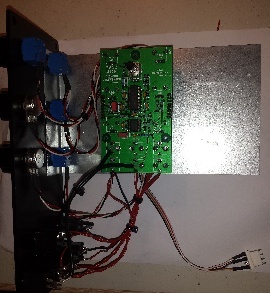
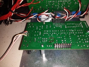
The “sandwich-layout” simply means the VCF is split in 2x PCB’s mounted in parallel on top of each other.
The Core-PCB contains the main circuit, while the Control-PCB contains the controlling elements as well as the buffers.
See the Build-Document for more detailed info/options regarding the build.
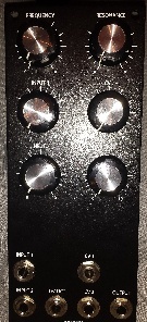
Main controls:
Frequency & Fine-tune
Resonance
Attenuators for Audio and FM inputs
Inputs:
2x Audio
2x FM
1V/OCT
Outputs:
Lowpass output
Technical details:
Width 12HP
Buffered inputs & output
Depth about 35mm, depending on choice of components
|
|
|
|
|
|
||