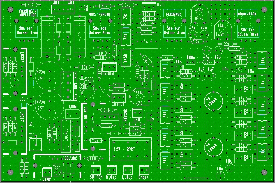
Project
Projecttitel: Juergen Haible Krautrockphaser in MOTM
Status: FINISHED
Startdate: 01.03.2014
Duedate: Juni 2014
Manufacture link: http://randomsource.net/haible/krautrock (randomsource Version
legacy page: http://www.jhaible.info/compact_clone/compact_clone.html
last update: 12 Jun.2015 for Randomsource Version
Description for Original Haible pcb (and randomsource Version) but the BOM is correct too, there is only a difference in design and extra Stage output, extra resonance pot option
Modifications Page: (CV MOD)
Schematics:
further buildinginfos:
http://www.dragonflyalley.com/constructionJHKrautrockPhaser.htm
building tip:
use sockets for the 33nF Film caps - see bugtrack info
use 50K REV LOG pot for osc periode and bridge wiper to left pin (rearview)
Bugtracking/Known Build Problems:
if your modulation pot doesn´t work, check your wiring at active/bypass switch and check that you have the Bridge at the OSC Periode Pins (see above) (its also shown in the schematics)
if your sound is have to many middle sound, try other capaciator values (original is 33nF) sometimes 47nf or 68nf sounds better.
Feedback - bridge Pin1-2 in every case on the Random Source PCB for the Feedback path
Feedback not working: don't use Modular Levels (5VPP) for audio input - otherwise FB isn't working as designed.
Bill of Materials (BOM)
Here's a list of components that I've used:
Krautrock Phaser BOM.
It only contains the components that are soldered to the board, no front panel components.
You'll want to have a nice "retro" looking lamp holder on th efront panel, too.
The incandescent lamp for the front panel is the same type as the two for illuminating the LDRs.
In Europe, E10 sockets are probably more common than elsewhere in the world. You can choose whatever socket you want - it just has to fit the lamp you're using. You can also simply solder the lamps to the PCBs with short, stiff wires, if you don't find a socket that fits into the PCB.
The lamps I'm using are 7V / 100mA types - spec'ed the same as in the original Compact A Phasing. If you cannot get these, you can try with 6.3V lamps of approximately the same power (0.7 Watt). In that case, you have to connect two 1N4002 diodes in series with these lamps. The PCB has the necessary pads and holes for this already, but I have not tested 6.3V lamps myself.
-> non standard homestock parts from BOM:
5W 120Ohm resistor axial (reichelt)
Relay: Finder 30.22.9 12 (reichelt)
1x 50K log pot (banzai)
3x 50k lin pot (banzai)
13 SMT 805/1206 100n capaciator (reichelt)
cmos CD4007 (reichelt)
12x ua741 or Lm741 (reichelt)
1x MC1458 - or LM1458 (reichelt)
(dont use TL072 ! )
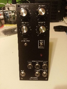
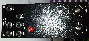
Basic Connection/Controls (common to all options)
Modulation Knob
50k linear Pot - to "MODULATION" on PCB
Feedback Knob
50k linear Pot - to "FEEDBACK" on PCB
Oscillation Period Knob
50k reverse log Pot - to "OSC. PERIOD" on PCB - bridge left to middle pin (shown rear view /not from frontpanel view) ![]() otherwise you got some soundissues
otherwise you got some soundissues
Modulation Depth Knob
50k linear Pot - to "PHASING / AMPLITUDE" on PCB
Bypass Momentary Switch
We chose an NKK ON-NONE-(ON) switch (Mouser 633-M201502-RO) from EFFECT ACTIVE / BYPASS to "SWITCH" on PCB
Mode Switch
DPDT switch from MODE switch AUTO - MANUAL to "MANUAL" on PCB
Modulation Indicator
Special panel mount E10 Lamp holder to LAMP on PCB
Bypass Pedal Jack
Isolated, nylon shaft 112A type jack (N112AX) to SWITCH on PCB (it's not clear to me that you can't use a regular 112AX jack but we're going to use the nylon one)
Rate Pedal Jack
Isolated, nylon shaft 112B (TRS) type jack (N112BX) to RATE on PCB
Depth Pedal Jack
Isolated, nylon shaft 114B type jack (N114BX) to AMOUNT on PCB
Input Jack
Switchcraft 112A Jack
Output L/Stereo Jack
Switchcraft 112A Jack
Output R/Mono Jack
Switchcraft 112A Jack
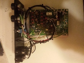
Build:

Background
If you listen to German records from the 1970's, you often hear a rather unique phasing that comes from a device called "Compact A Phaser" from the Berlin company "Gert Schulte Audio Elektronik". It's often referred to as "Schulte Phaser", and I have heard it being called "Krautrock Phaser", "Schulze Phaser" (because it's prominent on many early KS albums), "TD Phaser" (because of Tangerine Dream). In my opinion, this phaser has been important to the sound of these early electronic musicians almost as much as the synthesizers the used.
The new Compact Clone 2007
I've decided to do another redesign of that circuit and make a PCB layout.
All who have followed my DIY projects over the years know that I'm using the term "clone" rather loosely.
I'm not actually "cloning" anything, which would be a 1:1 reproduction of the original circuit and/or the appearance.
I certainly do strive for a most perfect reproduction of the sound that made a vintage design famous, but I also add features of my own that I find usefull, and tayler the circuit to my own needs and standards.
In case of the Compact Clone this means:
| Things I keep |
| The incandescent lamp / LDR combination that is responsible for the unique way of sweeping |
| Big incandescent lamp as sweep indicator on front panel |
| The circuit topology: 8 Stages of Phasing, 2 Stages of Feedback. Negative, lowpass-filtered feedback |
| The 741 opamps |
| The unique "Osc. Period" potentiometer that has maximum LFO rate on ccw end. (optional) |
| Works with original 7V 100mA lamps. |
| The possibility to mount potentiometers direcly on board. (Alps RK11 vertical mount types or similar.) Of course you can connect about every other potentiometer with wires, too. |
| Mains-Powered (optional). For +/-15V powered, see below. |
| Power supply for mains powering on the PCB, including secondary fuses, rectifiers, electrolytic caps, voltage regulators and heatsinks. |
| Things I change |
| It's possible to adapt the circuit to slightly different lamps and LDRs. |
| I've added a lot of coupling capacitors to keep offset voltages from the outputs |
| A Hard-Bypass with a relay that is controlled by an momentary switch. (Push: Turn on. Push again: Turn off.) Several of these switches can be wired in parallel, i.e you can have on on the front panel, and another one connected via jack for remote control. |
| Circuit redesigned for easily available potentiometers: 50k lin and 50k log (47k is the same, actually.) It's also possible to adapt it for slightly different pot values (feel free to ask), if your favorite form factor of potentiometer only comes in certain values. |
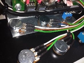
| You don't need that special "staircase" enclosure when using pcb-mounted potentiometers. In my version, the pots are mounted on the solder side of the board. So the component side looks down inside the enclosure, not being in th eway of the front (or rather "top") panel. |
| Complete redesign for +/-15V operation. Option for MOTM-style power connector on the PCB. |
| Large heatsinks and stronger Lamp Driver transistors. |
| Mains transformer and primary fuse not on PCB for safety reasons. |
| No DIN jack. Switch for LFO / Manual sweep on front panel 1/4" TRS jacks for remote control of Sweep Rate and Modulation Depth. |
TS:
Issue: no phasing
Solution: check the wiring of the momentary switch in my case a ON/(ON),maybe wiring wrong
Issue: LFO dont work:
the middle leg of the pot has to be connected to the CW end, but you can do this directly on the PCB, using a wire bridge at two of the 3 holes directly near the pot.
Some further tips and tricks:
http://electro-music.com/forum/topic-20373-475.html
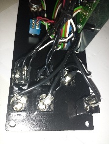
Shows the connectors (including "Amount") drawn in a way to resemble their physical appearance, as seen from the top of the PCB:
Left pin = sleeve
Middle pin = tip
Right pin = ring + switch contact for tip.
If you don't use a jack, jumper middle pin to right pin.
Using/testing:
connect input, left/right output
enable the active/bypass switch (LED goes on)
OSC Periode pot arround 50-75%
Modulation pot (= wet / dry mix) should be in 50% position.
For phasing effect, lamp should grow light and dim periodically.
Ambient light should be shut off (enclosure etc.)
Manual mode: Both R14 and R28 are connected to GND.
LFO mode: Neither R14 nor R28 are connected to GND.
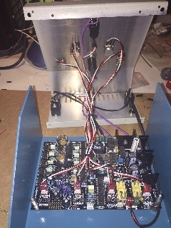
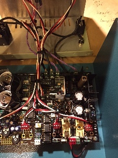
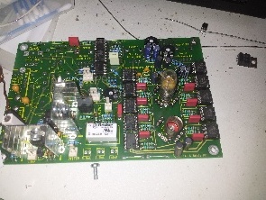
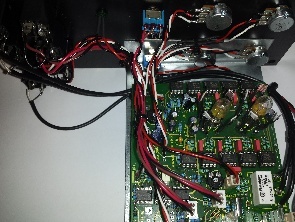
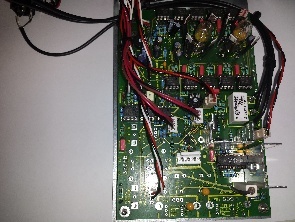
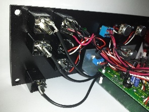
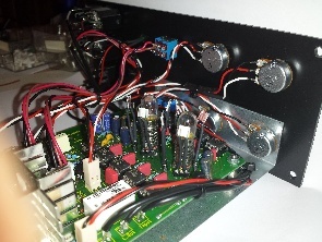
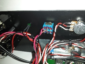
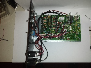
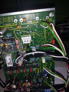
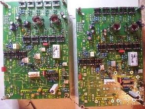
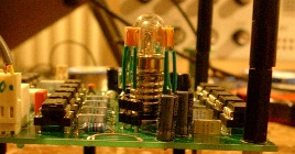
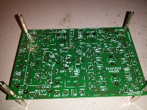
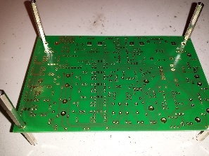
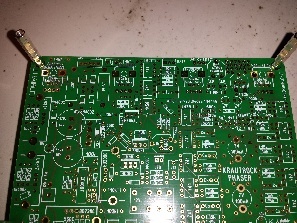
Gallery Pics for Original Haible PCB
Haible Krautrock Phaser Gallery
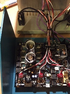
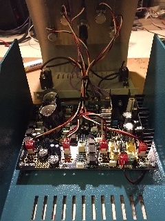
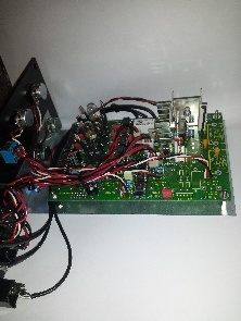

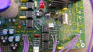
Gallery Pics for randomsource pcb
Further FAQ:
http://electro-music.com/forum/topic-20373-500.html
One more thing, though - the levels/frequencies mentioned in this case, is this in regards to the LFO signal or the audio signal?
| jhaible wrote: | ||||||
|
Loudness:
Coming back to the phaser and playing with it in a new track, I came to realize that its out volume is low compared to the signal volume coming in.
That is not necessary a problem, however raising the input volume does not raise the out volume, rather it gets the module into distortion wit ha constant volume out.
As it is a little too low for my taste, wanted to raise the out volume using the last op amp.
Is the resistor to tweak R57? what would be a good value to change it to?
No. Increase R54 and R58 instead.
JH.
R54/R58 = 2K4 in BOM
I tried the output volume mod as well as the feedbackpath mod and found both mods pretty useful.
R54 and R58 are 5.1K now, which feels closer to unity gain for me, but it is probably easier to overload the phaser with high feedback. ![]() approved by DSL-man, but try 4k7 too
approved by DSL-man, but try 4k7 too
_________________________
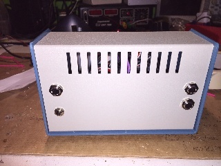
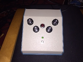
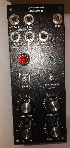
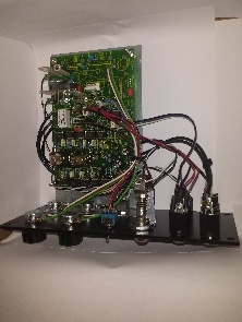
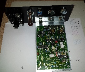
Standalone Version with randomsource Version pcb from 2015
Powersupply is a wandwart HQ power 18V AC with 1000mA
(its not needed to use a dual AC psu)