I offer a pcb on diysynth.de to change the onboard -8V power to a hum free solution for the THC SY-1 (all Versions)
The pcb was designed with the help of Simon Cox (SY-1M psycox CEO).
BOM: (or order an assembled Version from diysynth.de)
| Amount | Part | Source | Mouser | tme.eu |
|---|---|---|---|---|
| 1 | pcb | diysynth.de | ||
| 1 | LT1054 SOIC 8 | LT1054CS8-SMD | ||
| 1 | LM7908 | https://www.mouser.de/ProductDetail/ON-Semiconductor-Fairchild/LM7908CT?qs=%2fha2pyFadujt3%2f9kcI1ojRvjBqETND0G1EFAI2FtFq8%3d | https://www.tme.eu/de/details/lm7908ct/ungeregelte-spannungsstabilisatoren/on-semiconductor-fairchild/ | |
| 2 | 10uF tantal capacitor | 293D106X9025D2TE3 | ||
| 1 | 10pf capacitor SMT 0805 0603 | https://www.mouser.co.uk/ProductDetail/Wurth-Electronics/885012008019?qs=sGAEpiMZZMs0AnBnWHyRQEGbLOF2VP1iqcmVcmnwX7UxaJ2jp2TLLg%3d%3d | CL21C100JBANNNC | |
| 1 | 5mm metal spacer or a long M3 screw with washer and 2-3 M3 nuts | TFM-M3/5 plus 3mm washer and nut |
Build guide
INFO: I´m not responsible for your work or result, you need SMT soldering skills
PCB Assembly:
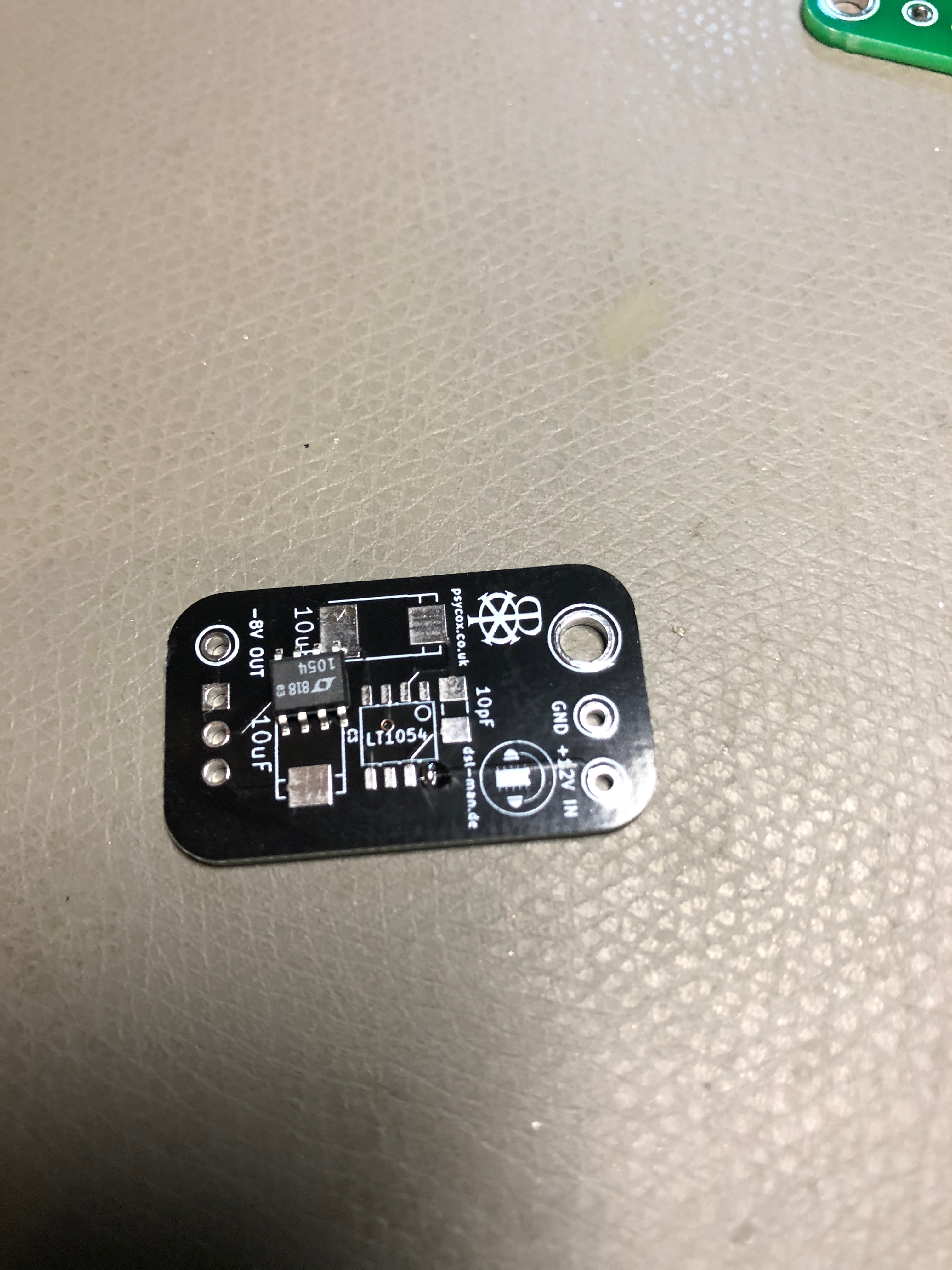
- solder the LT1054 on the pcb, double check the pinout !! for my LT1054 (from TME.eu) is the pinout as shown on bottom pictures, i haven´t checked the mouser version pinout.
i prefer to add a bit of soldercore on one pad, this gives you a easier placement of the IC.
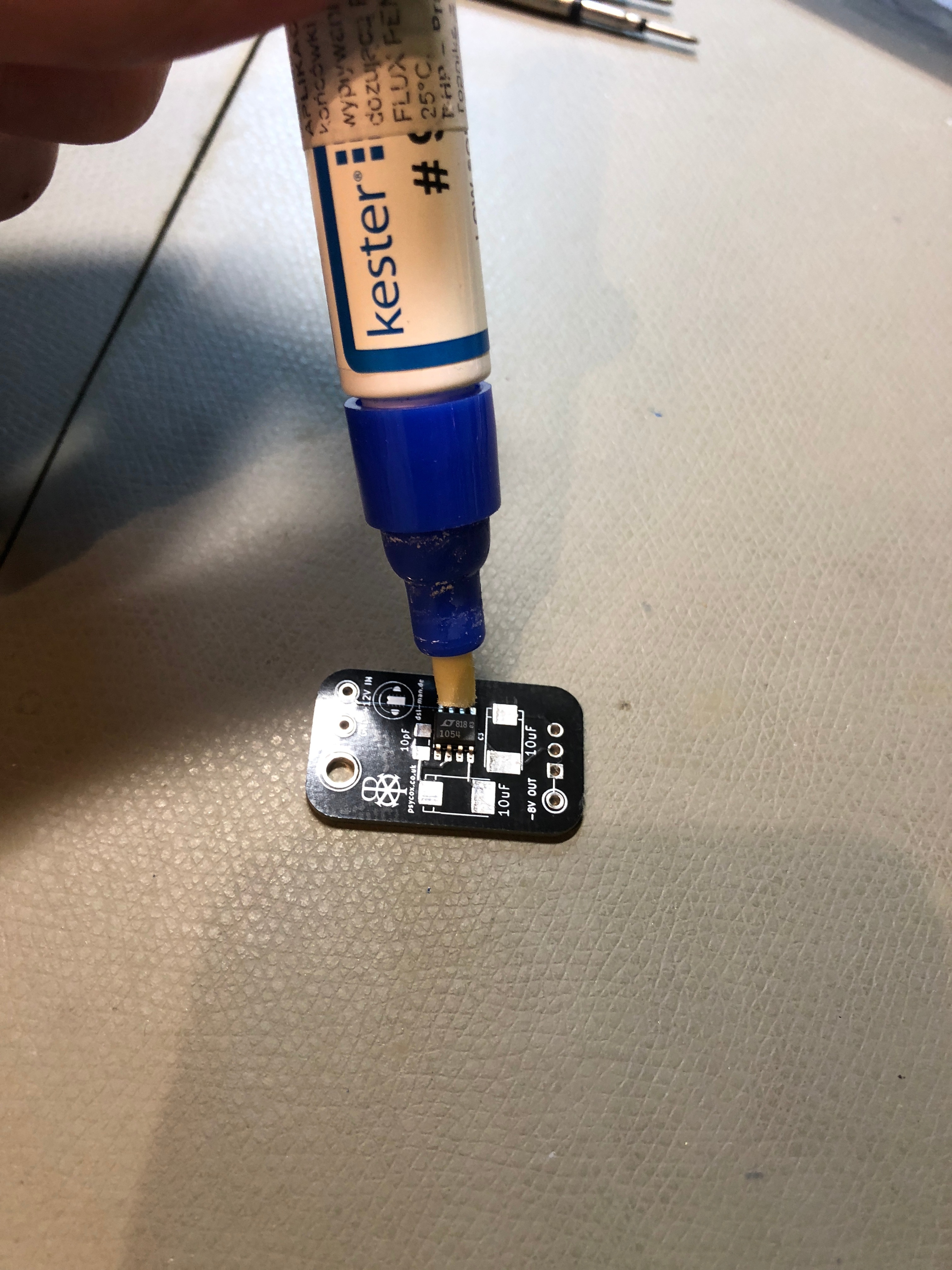
for the other pads use a kester flux pen for a better and easier soldering.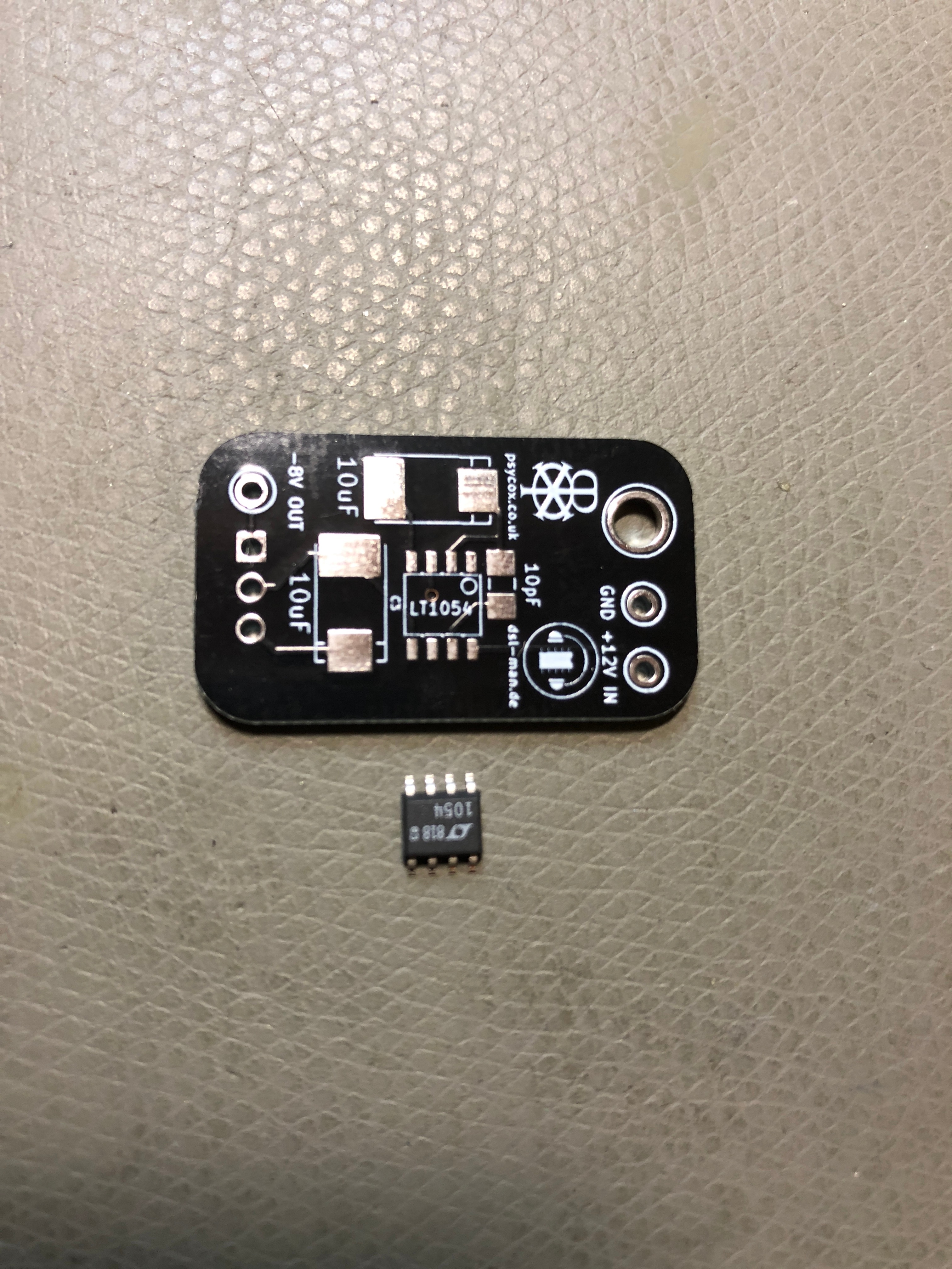
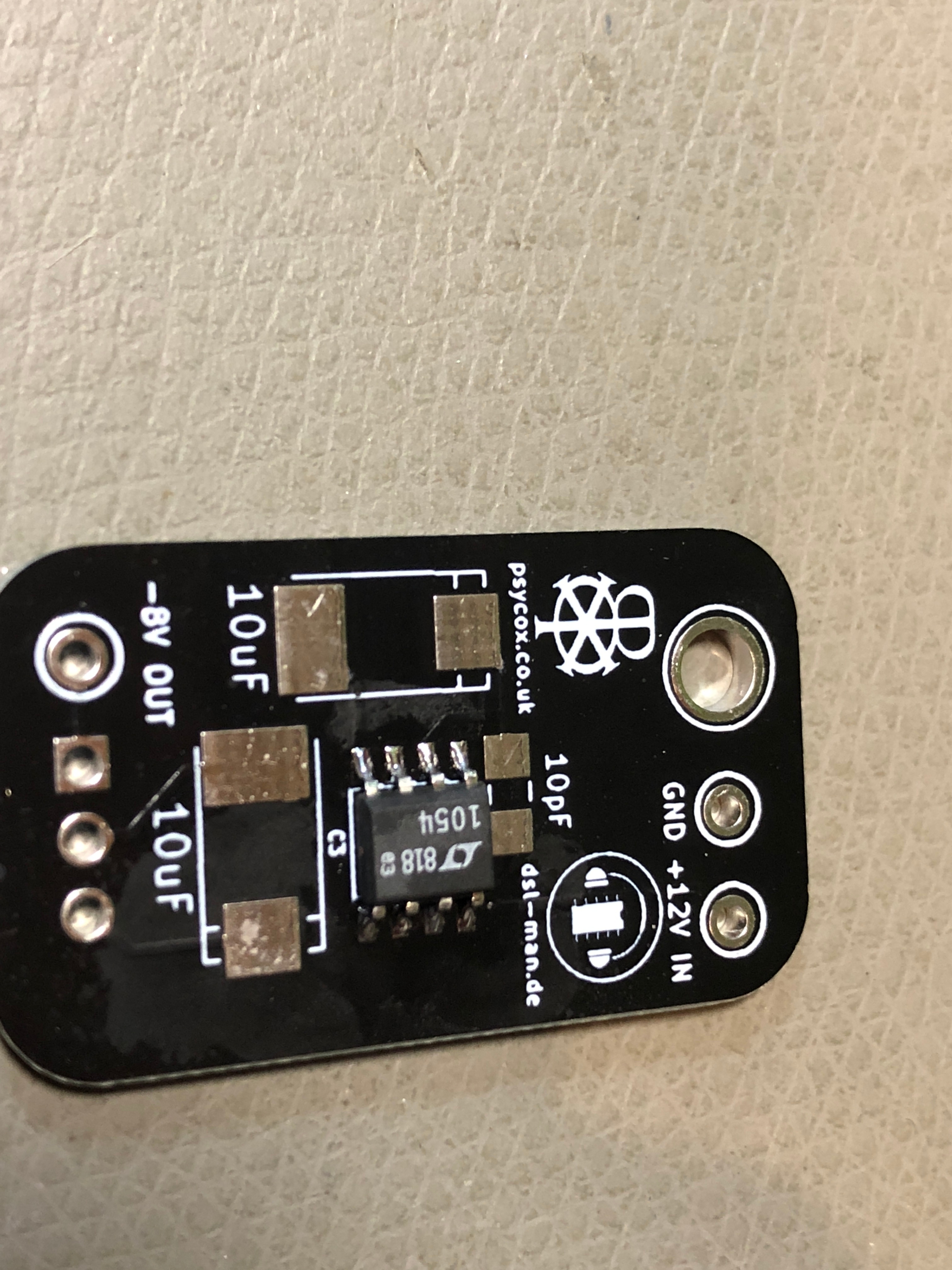
- solder the tantal capacitors
apply on one pad on each tantal capacitor pad, solder core.
place the part on in correct orientation on the pads (see bottom picture in case you dont know which polarity is used)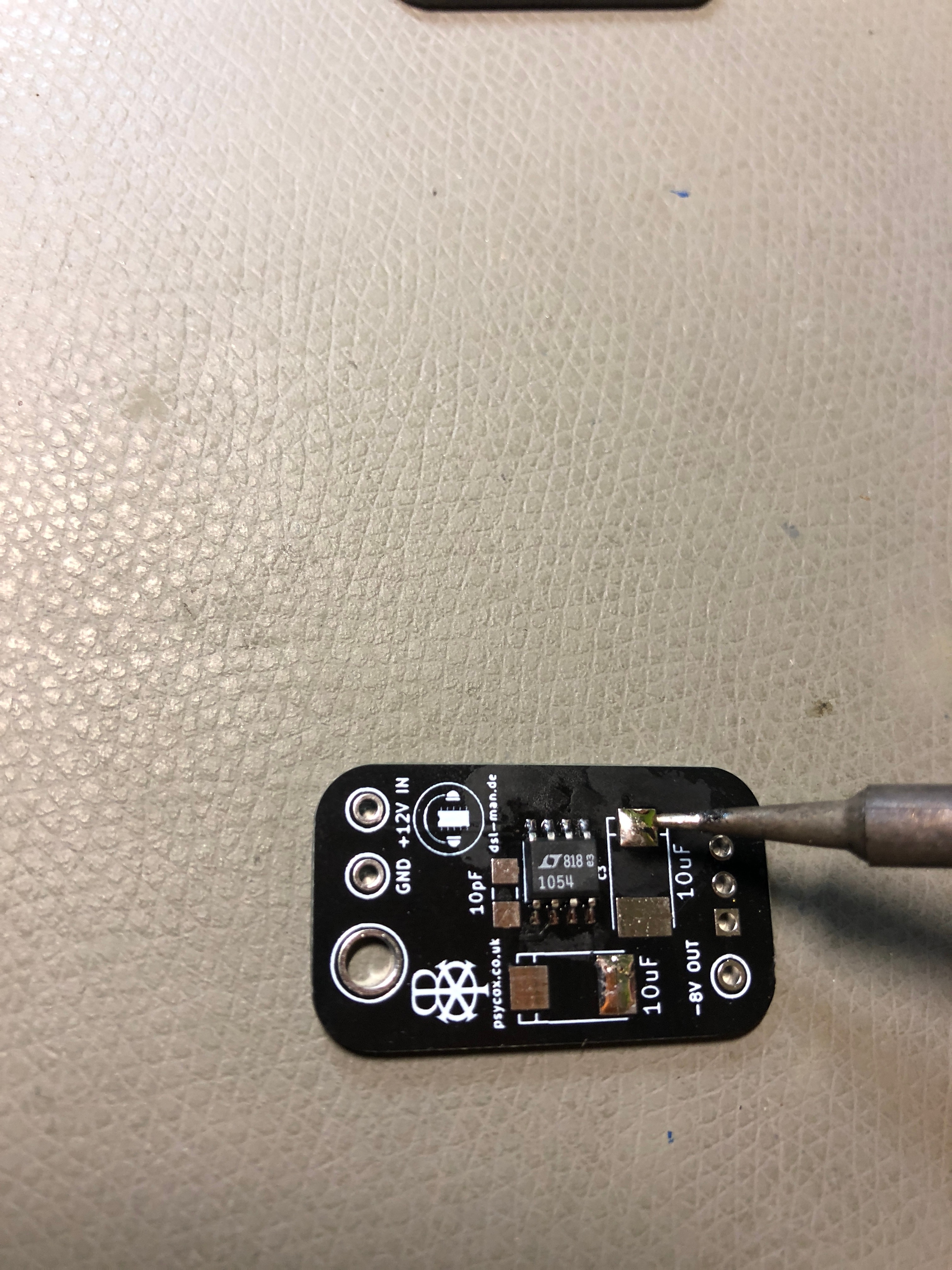
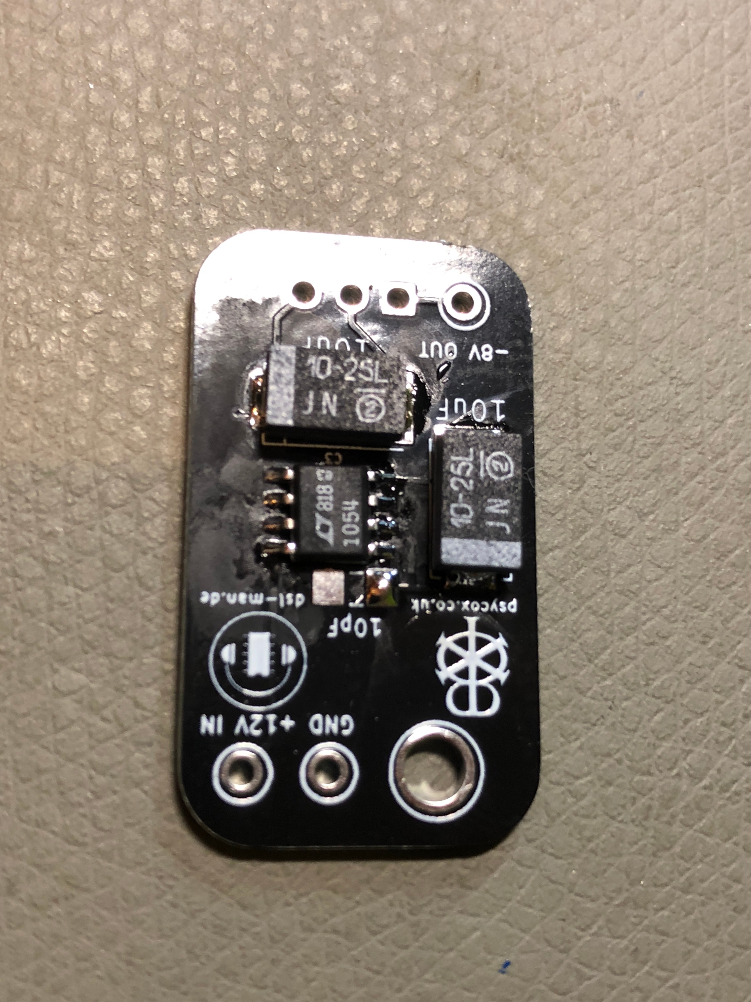
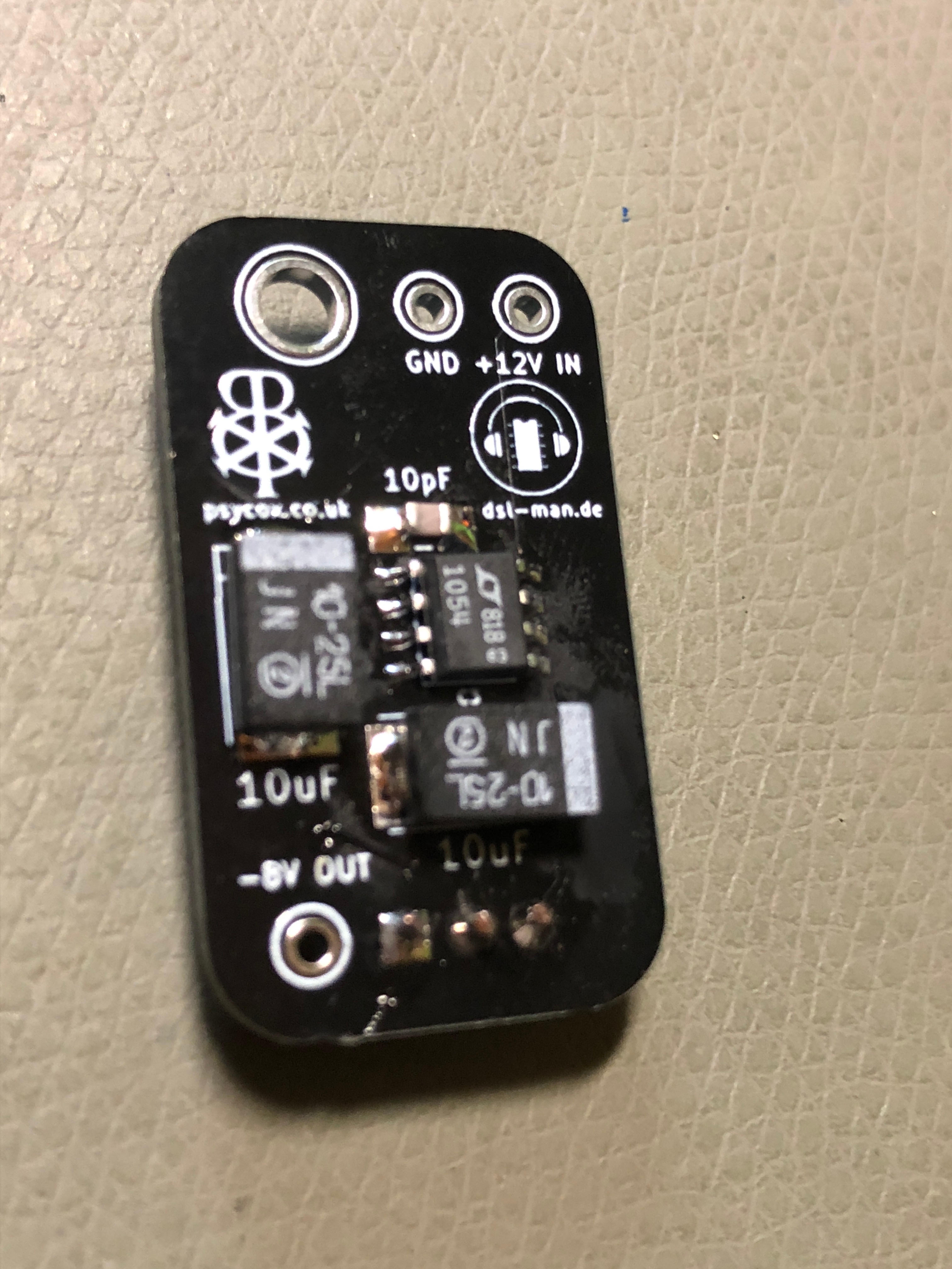
- solder the non polarity 10 pf capactitor on the pcb, start with one pad as described above
- turn the pcb
- bend the LM7908 pins to place it the shown orientation
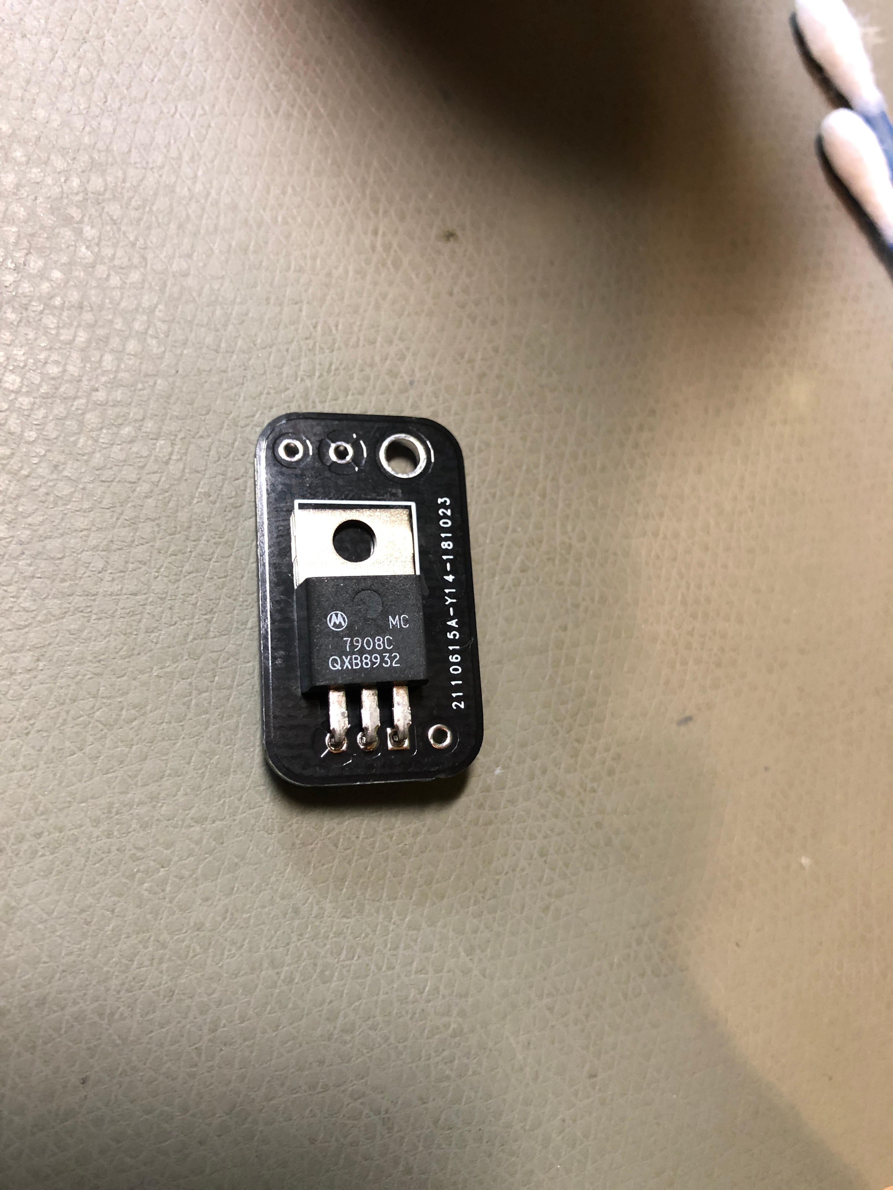
- solder all pins and check with a magnifier all pins
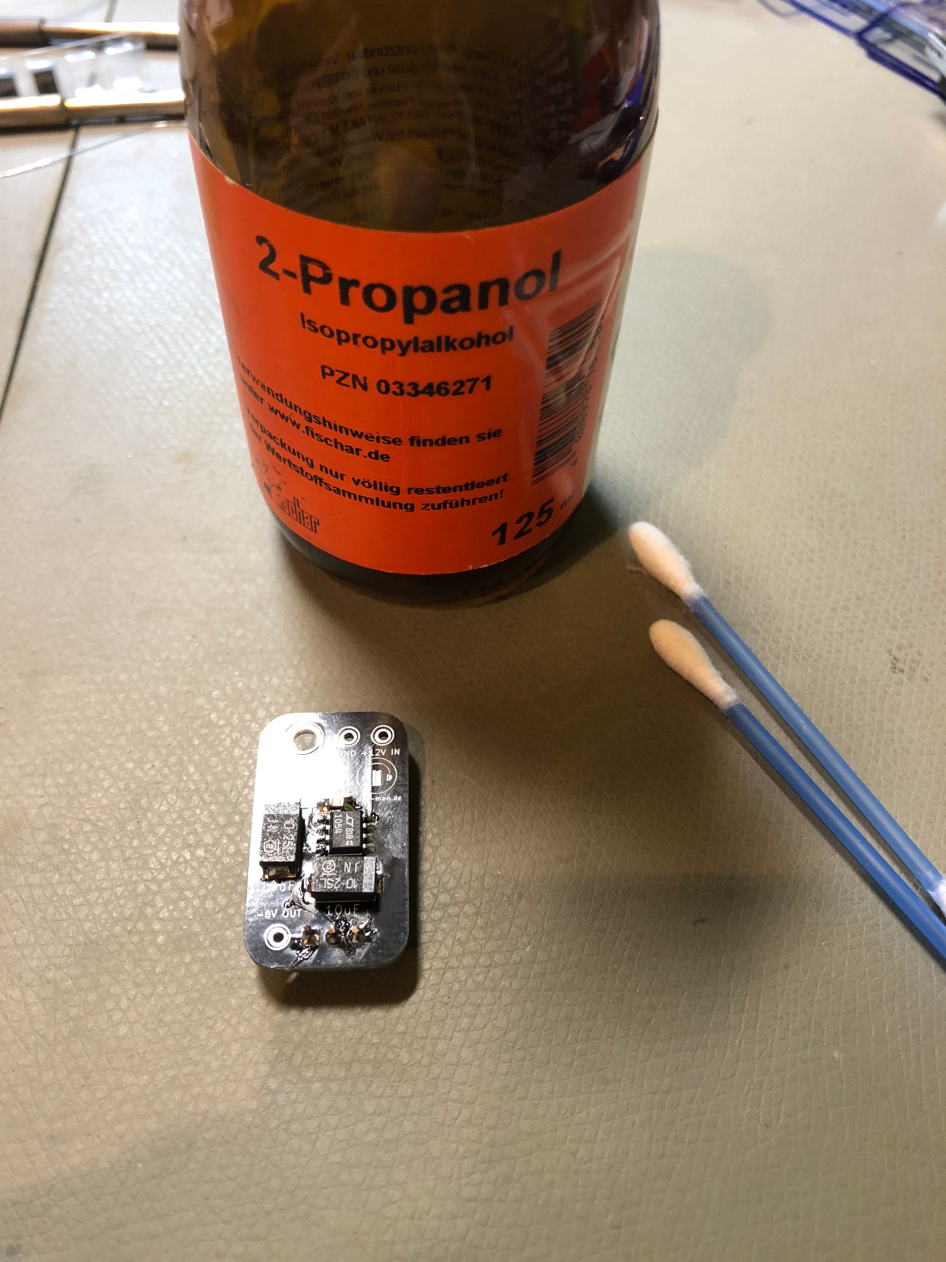
- clean the pcb with isoprop
Prepare your THC SY-1
- disconnect power and wait few minutes too uncharge the capacitors. (or move the powerswitch to on without powercord connected to the device, this unload the capacitor too)
- remove the screws and knob, slidercaps from the case
- open the device
- remove the metal distance bolts/spacer
- remove the controlboard pcb
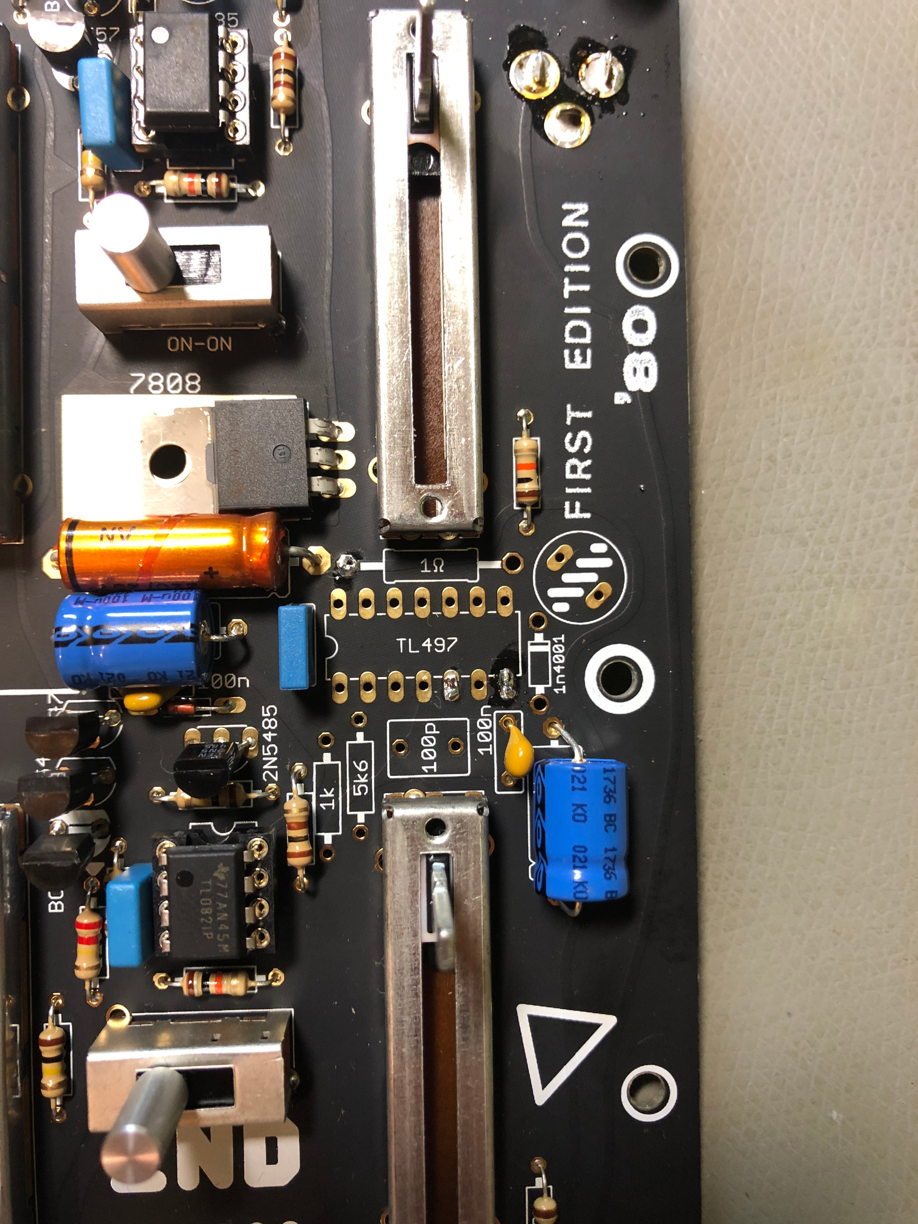
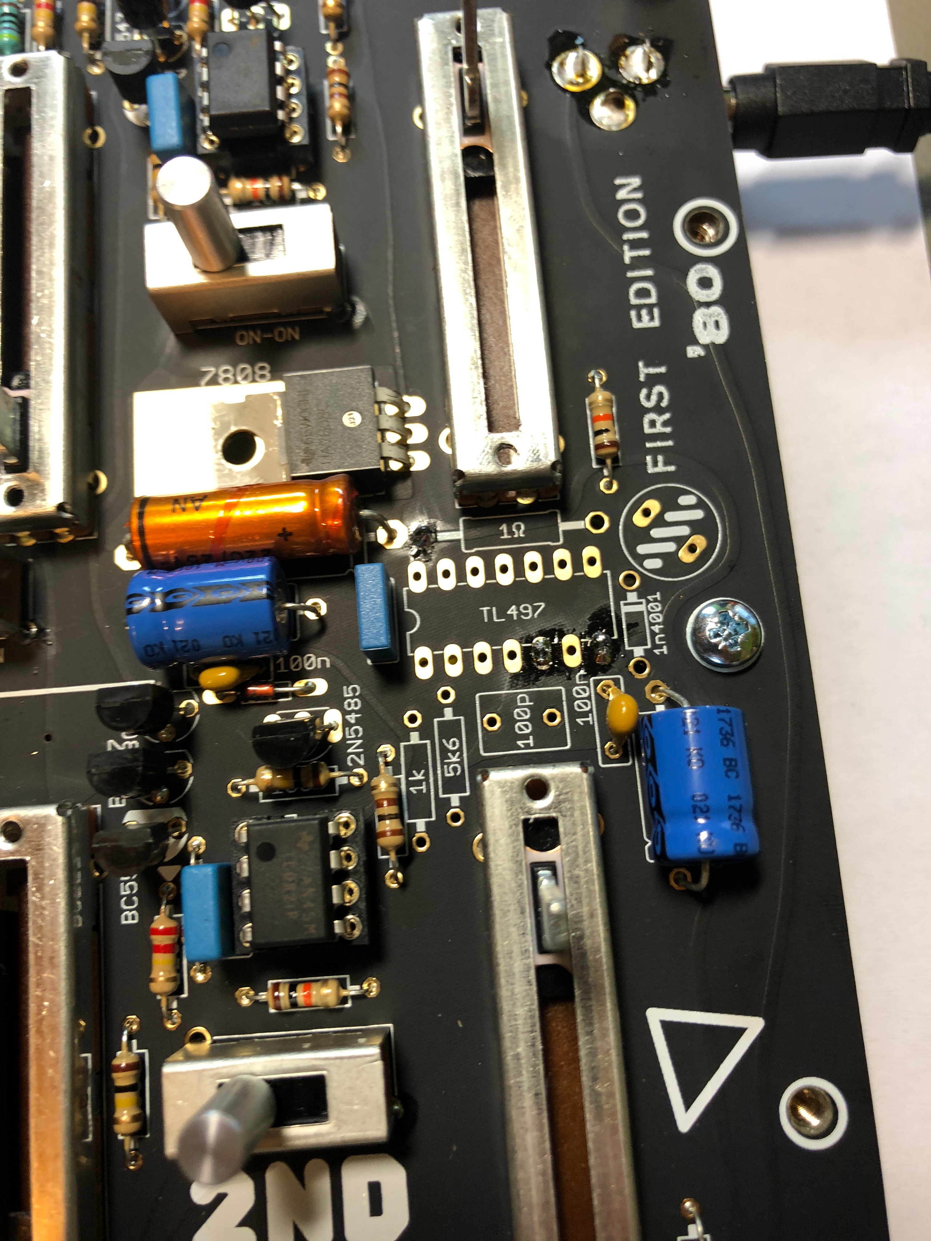
- remove all parts as shown on my picture:
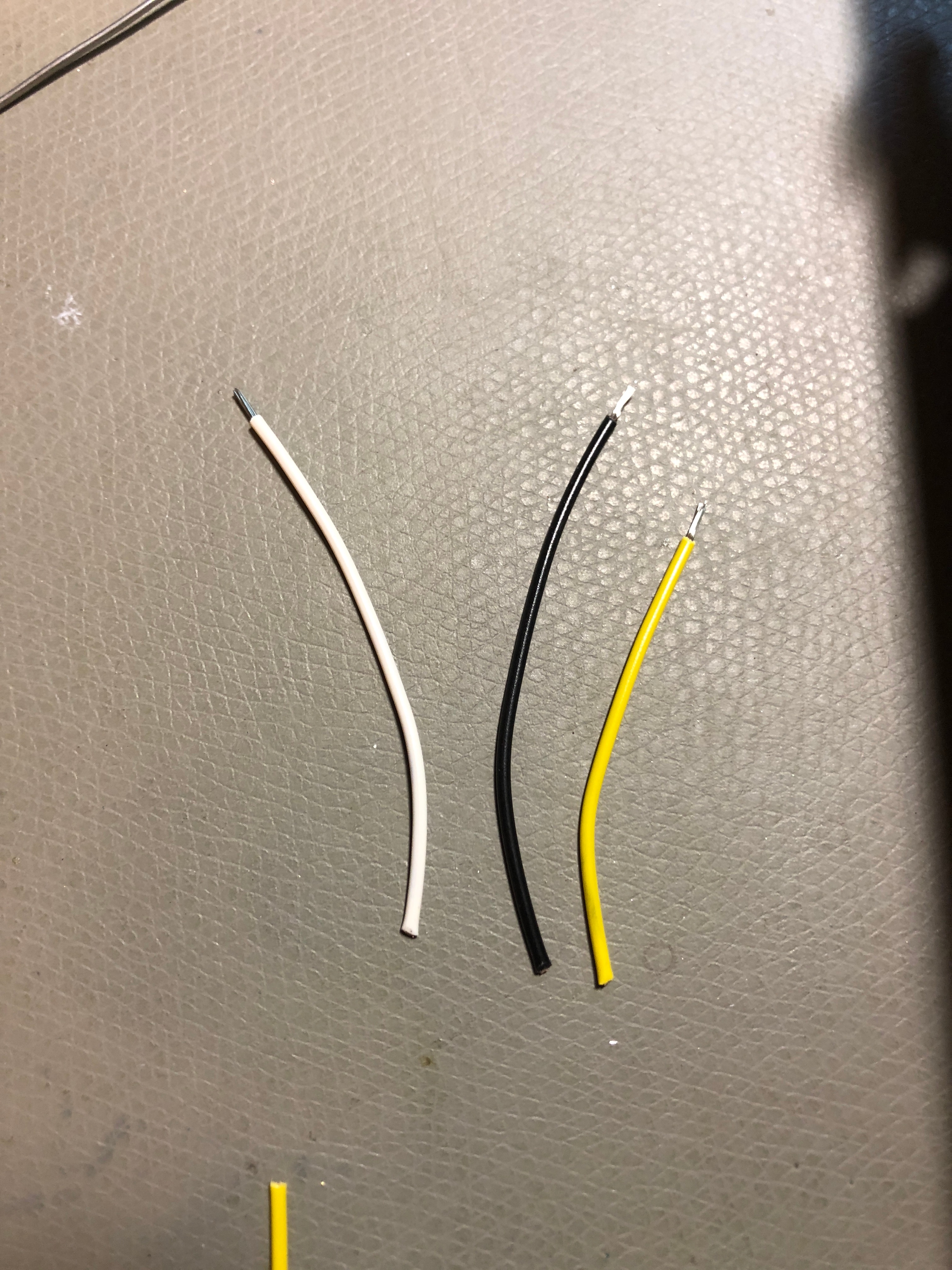
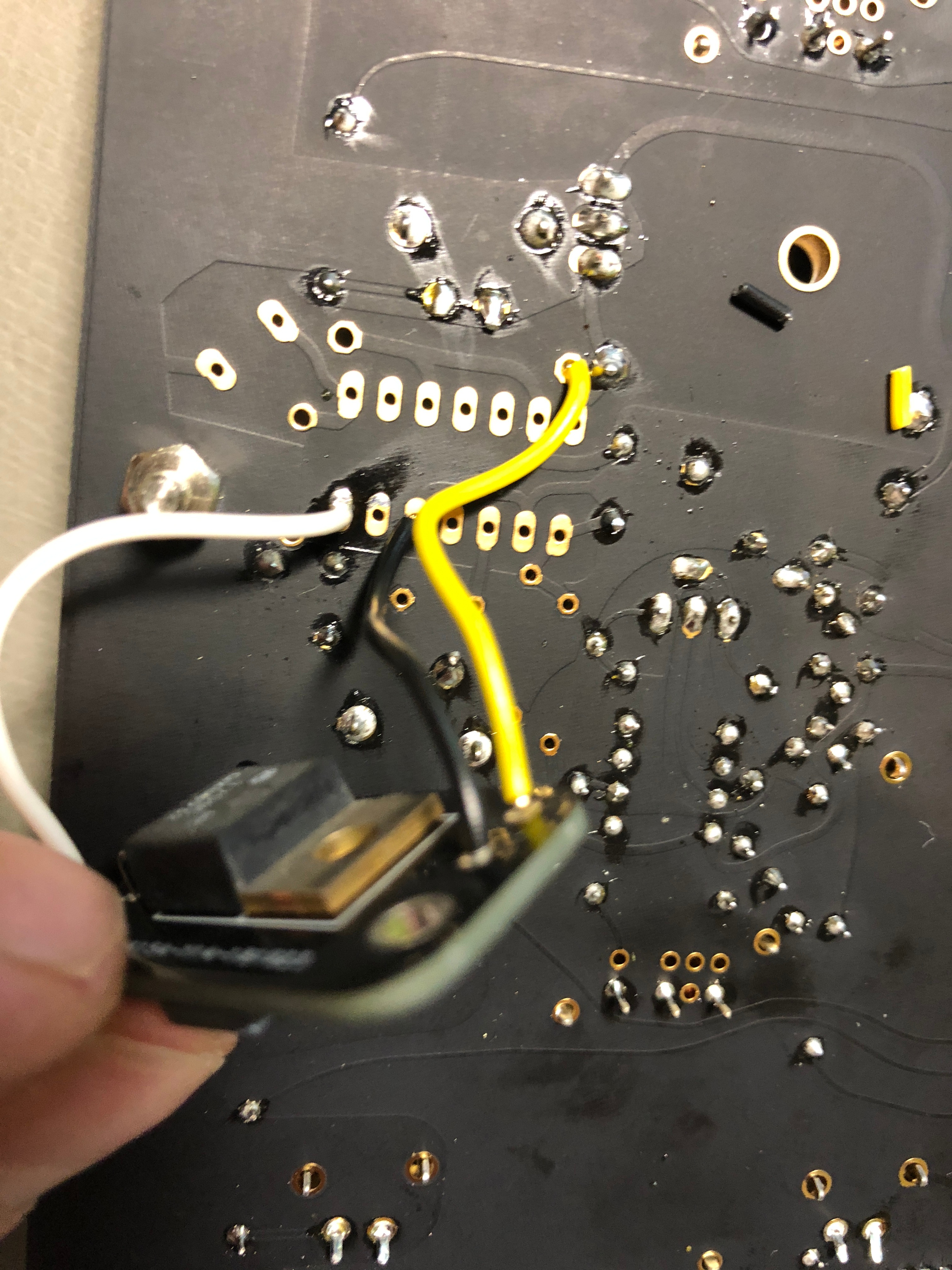
- prepare 3 short cables, each 7cm is fine - you can shorten it later
- solder the "yellow cable" to the 1R resistor pad hole as shown:
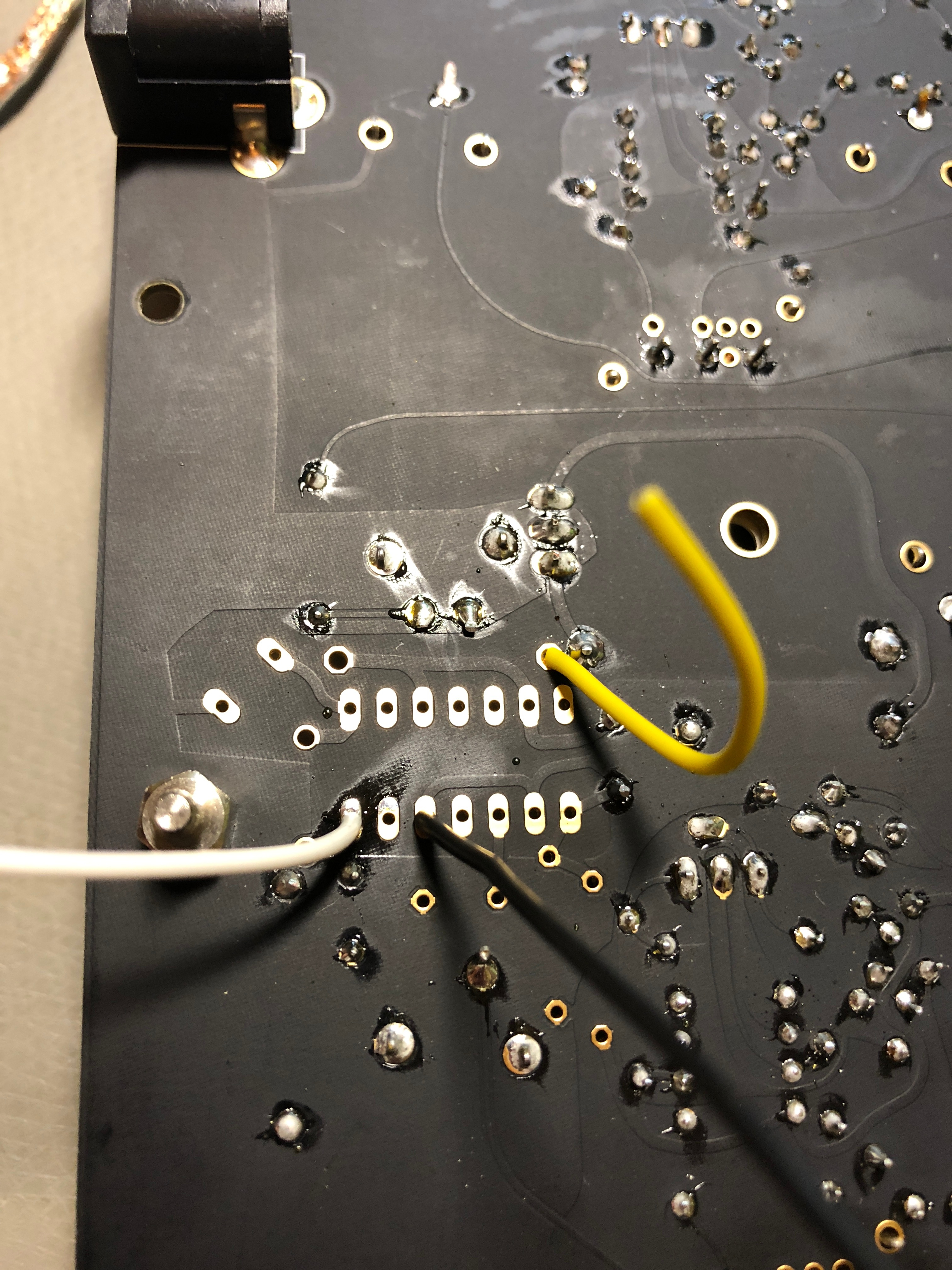
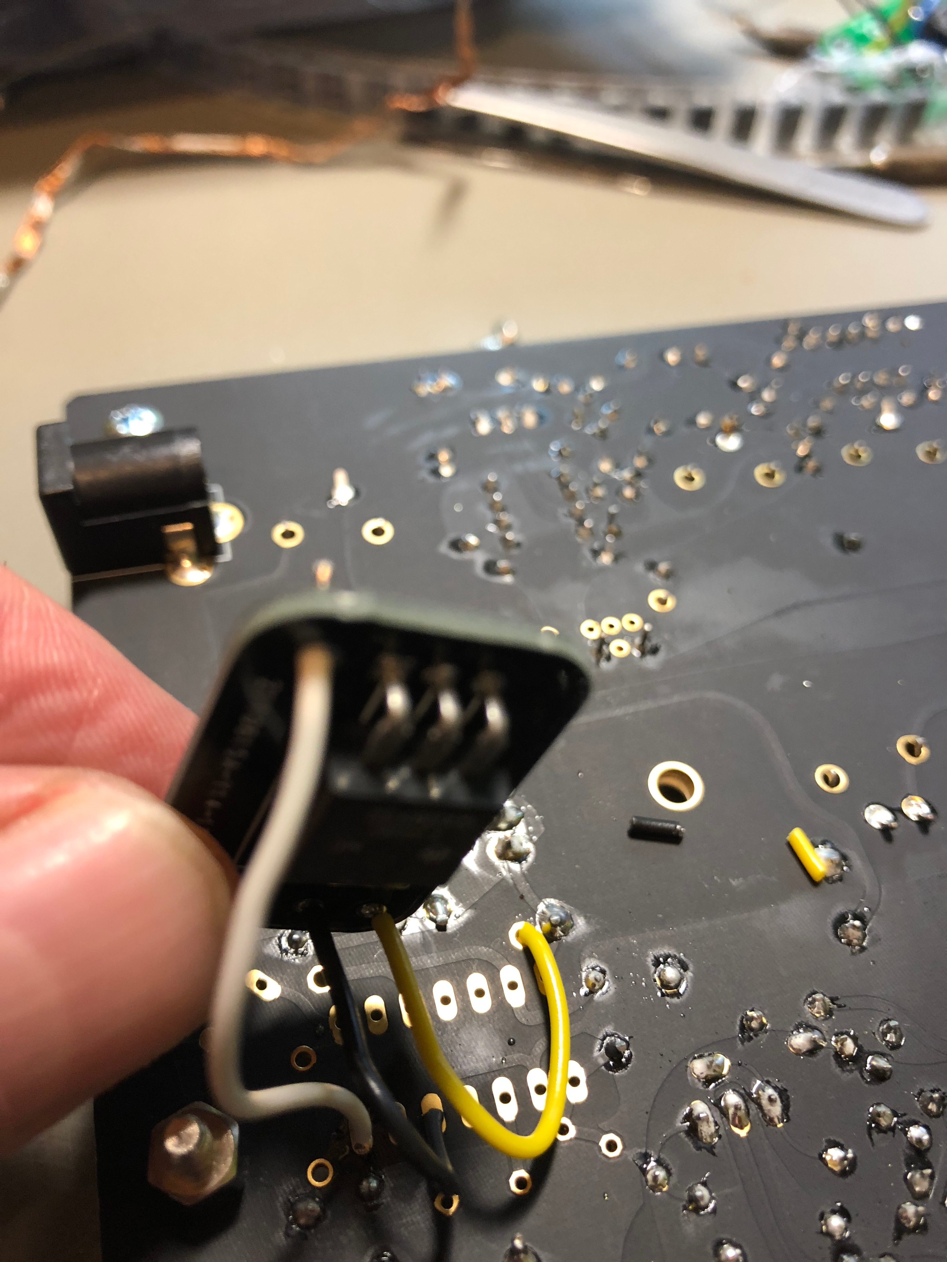
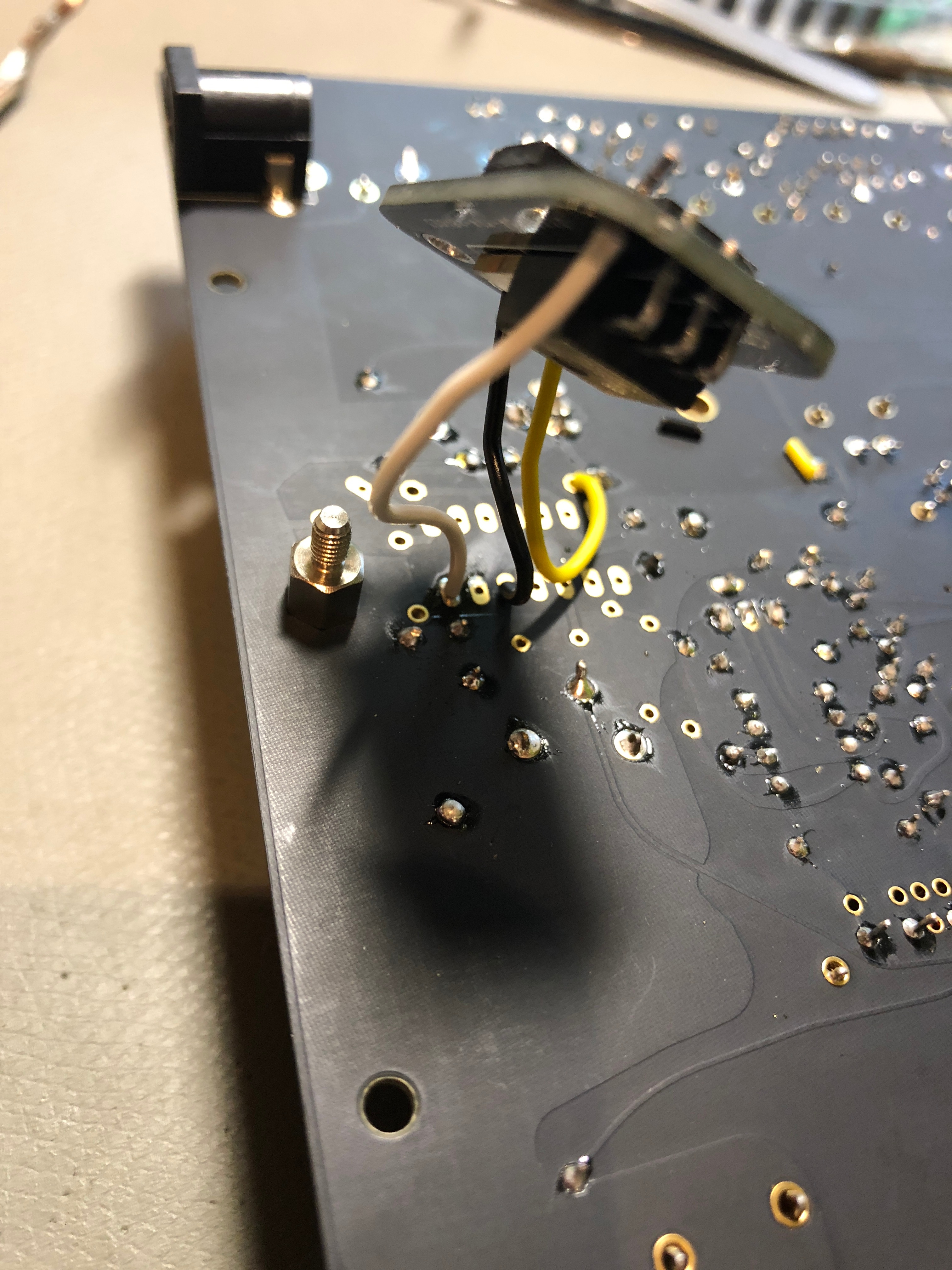
- Solder the white cable to the IC pad as shown:
- Solder the black cable as shown on the IC pad
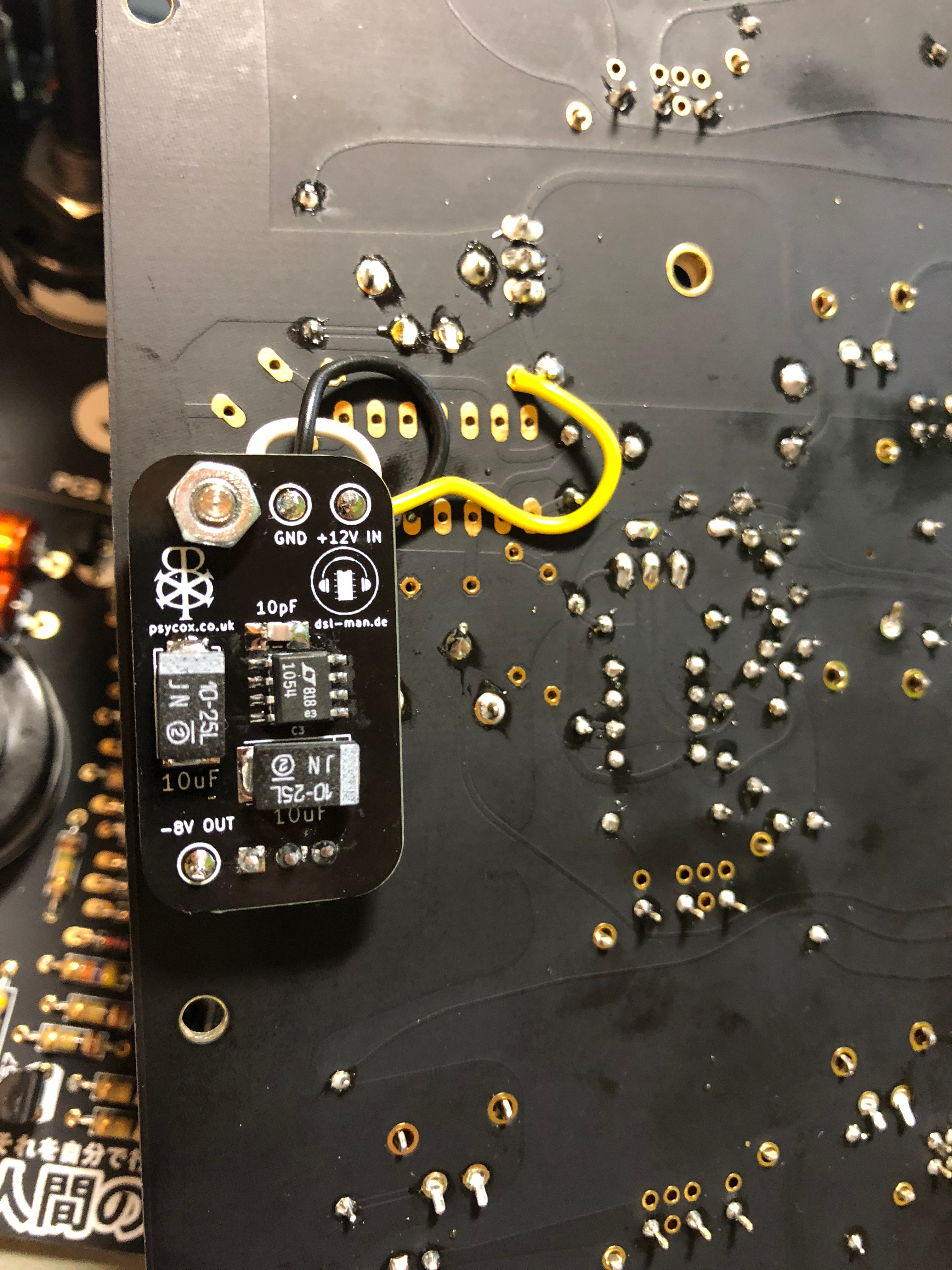
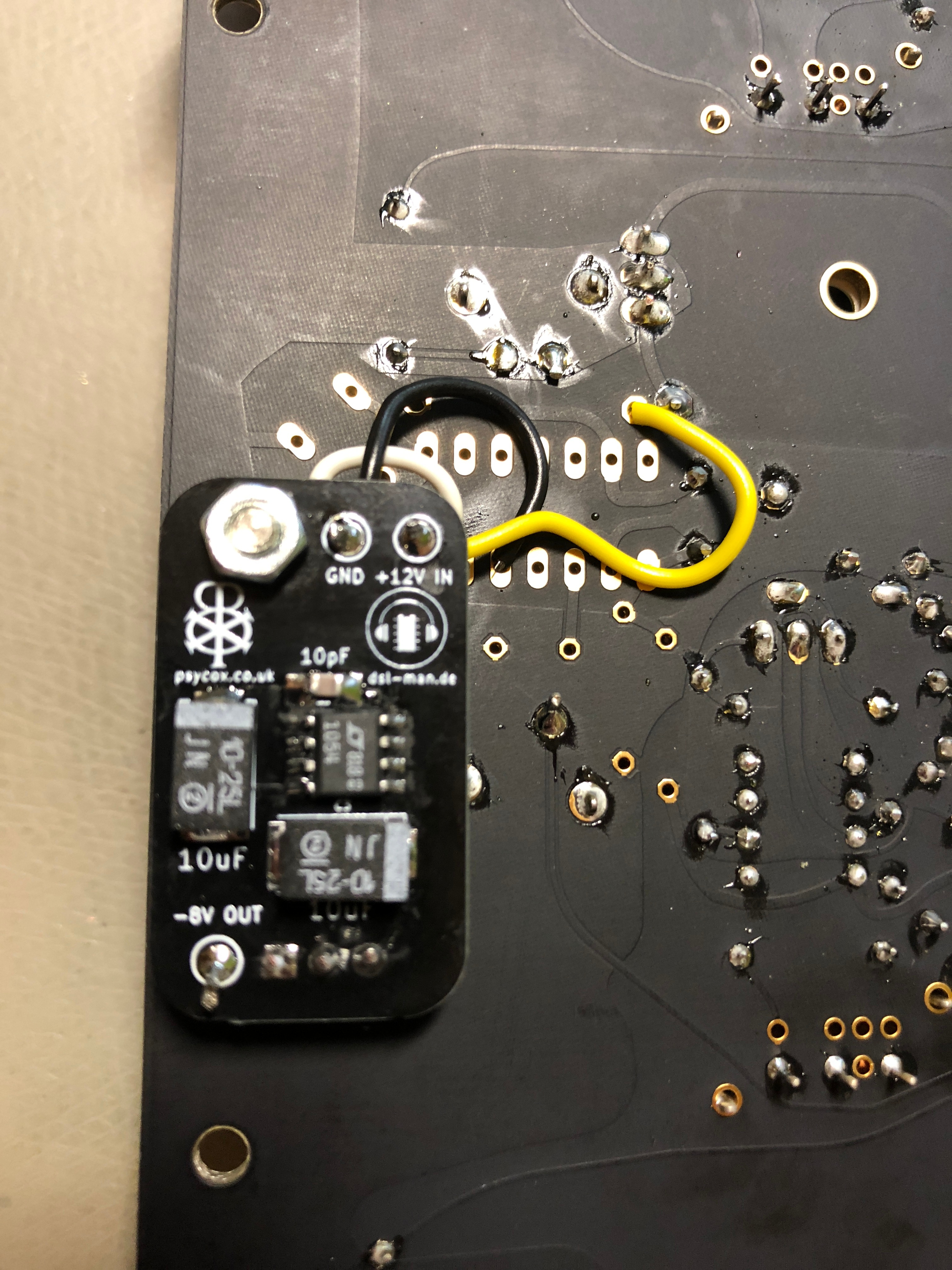
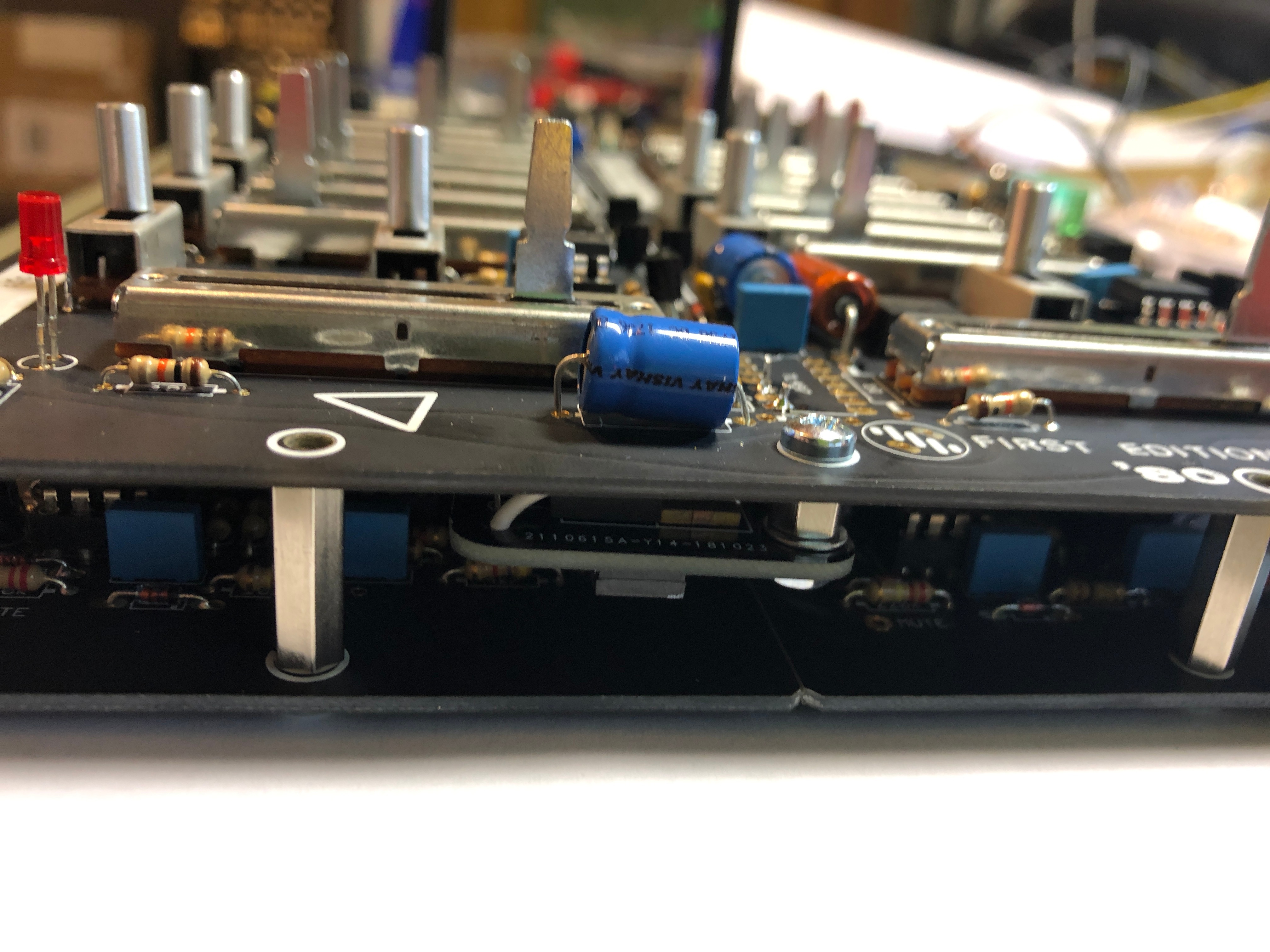
- mount the 5mm "metalspacer" or use a long screw with nuts between the pcbs to mount it as shown:
- Technical description: (yellow is connected on left side when shown from component side, black is ground and connected to pad (IC-PIN)2 or 5 when shown from component side, white ic connected to pin 7 (when shown from componet side)
white is the new -8Volt output
yellow is the 12V output from the syncussion which is connected to our new pcb LT1054 input.