| Panel | ||||||||||
|---|---|---|---|---|---|---|---|---|---|---|
| ||||||||||
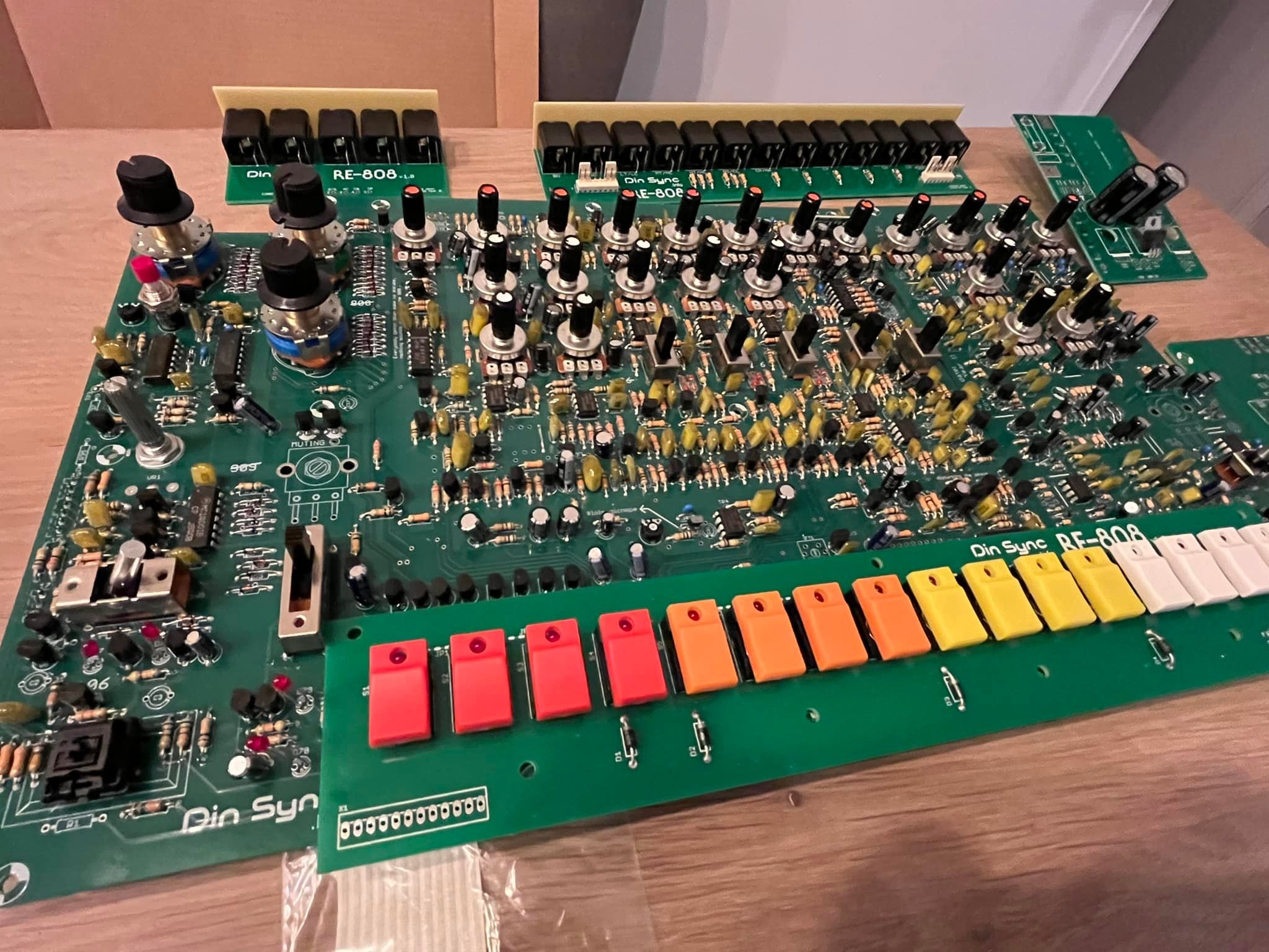
Projecttitel: RE-808Status:
Startdate: 11/2021Duedate: 08/2022Manufacture link: https://shop.re-303.com/product/re-808-bundle-3rd-run-advance-order/ |
source: Facebook.
after the RE-303, RE-606, RE-909 we have the RE-808 replica to build.
...
| ID | Issue | Fix | date | fixed version |
|---|---|---|---|---|
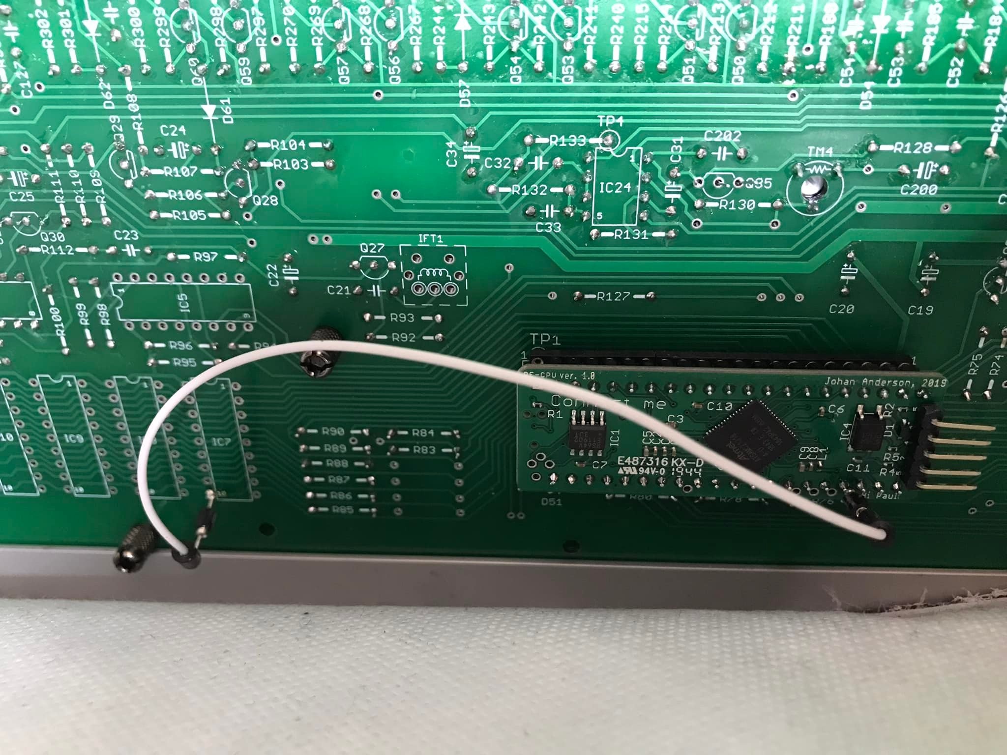
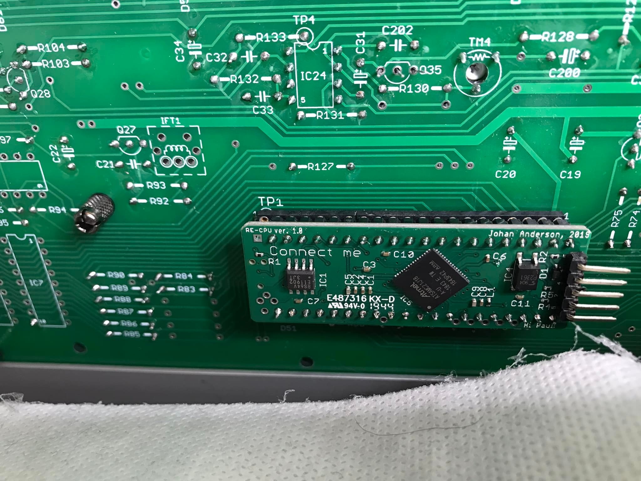
| 1 | CPU mounting | As you can see you also need to do a jumper wire between the solder point marked A on the pixie cpu and pin 10 (!WE pin) of *any* of IC 7,8,9 or 10 (they’re all connected to the same signal)
| 01/2022 | |
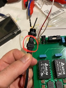
| 2 | PSU | Do not fit the DC jack on the PSU circuit board. Its not used and it is not wired correctly. use a cable for the jack as shown for example
| 01/2022 | |
| 3 | Tactiles /caps install | heres a tip about the installation of the tactile caps:
| 01/2022 |